Table of Contents
Advertisement
Quick Links
Advertisement
Table of Contents

Related Manuals for Netafim Fertikit 3G


Summary of Contents for Netafim Fertikit 3G
- Page 1 FERTIKIT ™ USER MANUAL V 001.08 - MAY 2015...
- Page 2 ANY FORM OR BY ANY MEANS, WHETHER ELECTRONIC, MECHANICAL, BY PHOTOCOPYING, RECORDING OR IN ANY OTHER MANNER WITHOUT PRIOR WRITTEN PERMISSION OF THE PUBLISHER. ALTHOUGH NETAFIM™ TAKES THE GREATEST POSSIBLE CARE IN DESIGNING AND PRODUCING BOTH ITS PRODUCTS AND THE ASSOCIATED DOCUMENTATION, THEY MAY STILL INCLUDE FAULTS.
- Page 3 Use of symbols The symbols used in this manual refer to the following: WARNING The following text contains instructions aimed at preventing bodily injury or direct damage to the crops, the FertiKit™ 3G and/or the infrastructure. CAUTION The following text contains instructions aimed at preventing unwanted system operation, installation or conditions that, if not followed, might void the warranty.
-
Page 4: Table Of Contents
CONTENTS Safety Safety instructions When using acid/chemicals Description Introduction Advantages Basic functions Operating principle Modularity Compatibility Service Maintenance Typical installation overview The 7 modes PL modes (PL/PS/PR/RL) PB mode SP mode MS mode (MS/RS) IL mode ST mode PD mode Operation and maintenance Operation Maintenance... -
Page 5: Safety
SAFETY CAUTION Read the Safety instructions chapter before using, maintaining or troubleshooting the FertiKit™ 3G. Safety instructions • All safety regulations must be applied. • Ensure that the installation is carried out in a manner that prevents leaks from the FertiKit the fertilizer/acid tanks and lines, the peripherals and the accessories (contaminating the environment, soil or ambient area). -
Page 6: When Using Acid/Chemicals
Imediately after each injection of any of the fertilizer combination above, flush the FertiKit™ with clean water for at least 2 minutes. In case of doubt regarding the use of any combination of fertilizers, contact your Netafim™ local representative. ATTENTION... -
Page 7: Description
High-quality components and PVC pipe work • Aluminum, corrosion-resistant frame with adjustable legs • Easy to install and to maintain • Made by Netafim™ Basic functions The FertiKit supports the following Nutrigation functions: • Fully controlled dosing and mixing of fertilizers/acid with source water into a homogenous nutrient solution. -
Page 8: Operating Principle
Suits all modes of FertiKit . Available in a wide variety of configurations, from a single dosing channel with 2 fertilizers to as many dosing channels and fertilizers as required. For further information, contact Netafim™. Compatibility The FertiKit 3G can be incorporated in an existing or a planned project;... -
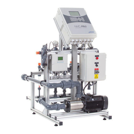
Page 9: Typical Installation Overview
DESCRIPTION Typical installation overview The drawing below represents the typical infrastructure suitable for the PL mode. Each one of the FertiKit™ 3G 7 modes fits a different infrastructure configuration. (see the schematic diagrams in Modes, pages 10-16). FertiKit Main parts of the FertiKit™ and its infrastructure The list below presents the Main parts of the FertiKit™... -
Page 10: Pl Modes (Pl/Ps/Pr/Rl)
DESCRIPTION PL modes (PL/PS/PR/RL) Operating principle: The pressure differential required to generate fertilizer suction via the Venturis is produced by a booster pump integrated in the FertiKit These modes of operation, where the lower manifold is under low pressure (around 0 bars/PSI), permits the use of high-efficiency Venturis with high suction capacity and low motive flow consumption. -
Page 11: Pb Mode
DESCRIPTION PB mode Operating principle: The pressure differential required to generate fertilizer suction via the Venturis is produced by a booster pump integrated in the FertiKit This mode of operation, where the smaller system pump is installed upstream from the Venturis, permits the use of a small booster pump, reducing the investment required and saving energy. -
Page 12: Sp Mode
DESCRIPTION SP mode Operating principle: The pressure differential required to generate fertilizer suction via the Venturis is produced by a booster pump integrated in the FertiKit This mode of operation, where the system pump is installed upstream from the Venturis, permits the use of a smaller booster pump, reducing the investment required and saving energy. -
Page 13: Ms Mode (Ms/Rs)
DESCRIPTION MS mode (MS/RS) Operating principle: For systems operating under negative suction - from a reservoir or a tank [max. height: 6 meters (20 feet)] Utilizes the main line pump pressure. Saves the need for a dosing booster. Flow rate: 20 - 700 m³/h (85 - 3000 GPM) Suitable for main line pressure: Upstream from the pump: -0.3 - +0.6 bar (-4 - +9 PSI) At the outlet of the pump: 2.5 - 6.5 bars (36 - 94 PSI) -
Page 14: Il Mode
DESCRIPTION IL mode Operating principle: The pressure differential required to generate fertilizer suction via the Venturis is produced by a booster pump integrated in the FertiKit In this mode of operation, the lower manifold is at low pressure (around 0 bar/psi) this allows the use of high-efficiency Venturis with high suction capacity and low motive flow consumption. -
Page 15: St Mode
DESCRIPTION ST mode Operating principle: For systems operating at low pressure - from an on-ground reservoir or a tank [max. height: 6 meters (20 feet)] The dosing booster pump also serves as main line pump. Supplied with a manual or a semi-automatic filter. Flow rate: 1 - 16 m³/h (4.4 - 70 GPM) Suitable for main line pressure: Upstream from the pump: -0.3 - +0.6 bar (-4 - +9 PSI) -
Page 16: Pd Mode
Saves the need for a dosing booster. Also suitable for applications where there is no electricity on the site (contact Netafim™). Flow rate: 10 - 200 m³/h (44 - 880 GPM) Suitable for main line pressure: 4.5 - 8.0 Bars (65 - 116 PSI) -
Page 17: Operation And Maintenance
MAP + Calcium Nitrate => Calcium Phosphate • Phosphoric acid + Calcium Nitrate => Calcium Phosphate In case of doubt regarding the use of any combination of fertilizers in the dual dosing channel, contact your Netafim™ local representative. FERTIKIT USER MANUAL 17... -
Page 18: Maintenance
OPERATION AND MAINTENANCE Maintenance CAUTION When opening or closing any manual valve, always do it gradually, to prevent damage to the system by water hammer. To prevent failures and extend the life cycle of the FertiKit , the user must carry out regular maintenance. •... -
Page 19: Winterization
OPERATION AND MAINTENANCE Winterization CAUTION When opening or closing any manual valve, always do it gradually, to prevent damage to the system by water hammer. In areas susceptible to freezing temperatures, if the system is not required for irrigation during the winter (mainly in open field applications) perform the following procedure to avoid damage caused by freezing when the FertiKit is idle for the winter period:... -
Page 20: Symptoms Regarding More Than One Single Dosing Channel
The controller settings regarding the field valves are correct (see the Controller Manual). Perform the actions in their order of appearance until the malfunction is fixed. If you identify faulty parts - consult your Netafim™ representative. CAUTION Only qualified electricians are permitted to perform electrical installations and repairs! CAUTION If isolation valves have been installed on the system, ensure that they are in closed position before troubleshooting any hydraulic malfunction. -
Page 21: Symptoms Regarding A Single Dosing Channel
If it is clogged - it should be dismantled and thoroughly cleaned (see the Dosing Booster Manual). If after implementing all the above steps the malfunction is still not fixed -consult your Netafim representative. Symptoms regarding a single dosing channel... -
Page 22: Symptoms While Idle
(internal deformation). If internal deformation is present - replace the Venturi (consult your Netafim™ representative). If after implementing all the above steps the malfunction is still not fixed - consult your Netafim™ representative. Symptoms while idle If the following symptoms occur while the FertiKit... -
Page 23: Switchboard Warning
10) If the malfunction is still not fixed - replace the dosing valve. If after implementing all the above steps the malfunction is still not fixed - consult your Netafim™ representative. Switchboard warning If the following symptom occurs during operation, perform the actions listed bellow: Switchboard warning light •... -
Page 24: Warranty
The above does not apply to EC and pH sensors, since they are wearable. Netafim™ will warrant these items to be free of defects in material and workmanship for 3 months from the date of installation, provided the installation has been reported to Netafim™... -
Page 25: Appendix 1 - Calibration
APPENDIX 1 - CALIBRATION The process of calibrating the FertiKit is carried out in three stages: 1. Calculation of dosing channels opening percentage To finely calibrate the FertiKit in order to achieve homogeneous and stable dosing, perform the following calculation for each dosing channel (fertilizers and acid) to determine the amount of suction reduction needed to attain the required fertilizer/acid flow rate. - Page 26 APPENDIX 1 - CALIBRATION Note the required dosing ratio of each fertilizer solution and the dosing ratio of the acid solution (if used). Fill a bucket with 10 liters (2 US gallons) of the client's supply water (without fertilizer or acid). Measure the EC and the pH levels of the water in the bucket using calibrated portable sensors.
-
Page 27: Tm While Irrigating
APPENDIX 1 - CALIBRATION With the controller set to operate according to EC/pH values - if the EC and pH values measured in the bucket are within a range of ±30% deviation from the target values, the system will be able to correct them automatically. - Page 28 APPENDIX 1 - CALIBRATION If the EC and pH target values cannot be attained, and the dosing valves are opened more than 85%, measures should be taken to increase the dosing ratio - if feasible, slightly increase the concentration of the fertilizer solution and/or reduce the water flow rate to the field during irrigation.
- Page 30 30 FERTIKIT USER MANUAL GROW MORE WITH LESS WWW.NETAFIM.COM...
Need help?
Do you have a question about the Fertikit 3G and is the answer not in the manual?
Questions and answers