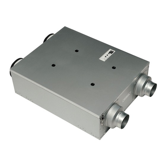
Panasonic FV-10VEC1 Service Manual

Panasonic FV-10VEC1 Service Manual

Energy recovery ventilator

Advertisement

Service Manual
This service information is designed for experienced repair technicians only and is not designed for use by
the general public. It does not contain warnings or cautions to advise non-technical individuals of potential
dangers in attempting to service a product. Products powered by electricity should be serviced or repaired
only by experienced professional technicians. Any attempt to service or repair the product or products dealt
with in this service information by anyone else could result in serious injury or death.
There are special components used in this equipment which are important for safety. These parts are
marked by
in the Schematic Diagrams, Exploded Views and Replacement Parts List. It is essential
that these critical parts should be replaced with manufacturer's specified parts to prevent shock, fire
or other hazards. Do not modify the original design without permission of manufacture.
We suggest to handle such parts after the static electricity prevention.
It is forbidden to touch the PCB parts by bare hands during the repairing process.
CONTENTS
1.Specifications
2.Parts Identification
3.Wiring Diagram
4.Parts List
5.Troubleshooting Guide
WARNING
IMPORTANT SAFETY NOTICE
Energy Recovery Ventilator
(North America Market)
PEG1610044CE
Version:1601
FV-10VEC1
FV-10VE1
PAGE
1
2~11
12
13~18
19

Advertisement

Table of Contents
loading

Summary of Contents for Panasonic FV-10VEC1

  • Page 1 Version:1601 Service Manual Energy Recovery Ventilator (North America Market) FV-10VEC1 FV-10VE1 WARNING This service information is designed for experienced repair technicians only and is not designed for use by the general public. It does not contain warnings or cautions to advise non-technical individuals of potential dangers in attempting to service a product.
  • Page 2: Specifications

    1. Specifications...
  • Page 3: Parts Identification

    2. Parts Identification FV-10VEC1 Main Body Section Frame Body Assy (2pcs) (5pcs) (4pcs) EA Fan Assy SA Fan Assy (6pcs) (2pcs) PCB Box Assy (2pcs) (2pcs) a a a a a a a a a a a a a a a a a a a a a a...
  • Page 4 2. Parts Identification FV-10VEC1 Frame Body Assy (2pcs) (4pcs) (8pcs) (2pcs) (2pcs) (2pcs) (2pcs) SA Fan Assy/EA Fan Assy (4pcs) (4pcs) (4pcs)
  • Page 5 2. Parts Identification FV-10VEC1 PCB Box Assy (2pcs) (3pcs) (3pcs) (2pcs) (2pcs) (4pcs) Frame Cover Assy (4pcs) (2pcs) (4pcs) (2pcs)
  • Page 6 2. Parts Identification FV-10VEC1 Main Labels AIR FLOW...
  • Page 7 2. Parts Identification FV-10VEC1 Packing Case Assy (4pcs) (4pcs) (6pcs)
  • Page 8 2. Parts Identification FV-10VE1 Main Body Section Frame Body Assy (2pcs) (2pcs) EA Fan Assy (4pcs) SA Fan Assy (6pcs) (2pcs) PCB Box Assy (2pcs) (2pcs) a a a a a a a a a a a a a a a a a a a a a a (2pcs) a a a a a a...
  • Page 9 2. Parts Identification FV-10VE1 Frame Body Assy (2pcs) (4pcs) (8pcs) (2pcs) (2pcs) (2pcs) (2pcs) SA Fan Assy/EA Fan Assy (4pcs) (4pcs) (4pcs)
  • Page 10 2. Parts Identification FV-10VE1 PCB Box Assy (2pcs) (3pcs) (3pcs) (2pcs) (2pcs) (4pcs) Frame Cover Assy (4pcs) (2pcs) (4pcs) (2pcs)
  • Page 11 2. Parts Identification FV-10VE1 Main Labels AIR FLOW...
  • Page 12: Parts Identification

    2. Parts Identification FV-10VE1 Packing Case Assy (4pcs) (4pcs) (6pcs)
  • Page 13: Wiring Diagram

    3. Wiring diagram FV-10VEC1 FV-10VE1...
  • Page 14: Parts List

    4. Parts List FV-10VEC1 Main Body Section Part No. Part Name Q'ty Remark FFV1600152S Frame Body Assy FFV0720012S Cord Bushing FFV4620115S Power Cord FFV6710047S Wiring Cover FFV3740038S Maintenance Plate FFV4300151S OA Damper Assy Include Temperature Sensor FFV3402188S EA Damper Assy...
  • Page 15 4. Parts List FV-10VEC1 SA Fan Assy/EA Fan Assy Part No. Part Name Q'ty Remark FFV1610079S Fan Assy FFV7020022S Nut FFV4710409S Casing FFV7000074S Truss Tap Screw FFV7000089S Truss Tap Screw PCB Box Assy Part No. Part Name Q'ty Remark FFV5580017S Switch Assy...
  • Page 16 4. Parts List FV-10VEC1 Main Labels Part No. Part Name Q'ty Remark FFV0000165S AHU Label FFV3402194S Earth Label FFV0020003S Air Flow Arrow FFV6710048S Wiring Label FFV4020861S Name Plate FFV5580022S Switch Label FFV4690029S Power Cord Label Packing Case Assy Part No.
  • Page 17 4. Parts List FV-10VE1 Main Body Section Part No. Part Name Q'ty Remark FFV1600156S Frame Body Assy FFV0720012S Cord Bushing FFV4620115S Power Cord FFV6710047S Wiring Cover FFV3740038S Maintenance Plate FFV4300151S OA Damper Assy Include Temperature Sensor FFV3402189S EA Fan Assy FFV3702280S SA Fan Assy FFV1600153S Frame Bracket Assy FFV1600154S Frame Bracket Hook...
  • Page 18 4. Parts List FV-10VE1 SA Fan Assy/EA Fan Assy Part No. Part Name Q'ty Remark FFV4710409S Casing FFV7000074S Truss Tap Screw FFV7000089S Truss Tap Screw PCB Box Assy Part No. Part Name Q'ty Remark FFV5580017S Switch Assy FFV5580016S Switch PCB Cover Assy FFV5580010S Switch Knob FFV5580011S Switch Spring FFV5580018S Switch PCB Assy...
  • Page 19: Parts List

    4. Parts List FV-10VE1 Main Labels Part No. Part Name Q'ty Remark FFV0020003S Air Flow Arrow FFV6710050S Wiring Label FFV4020862S Name Plate FFV5580022S Switch Label FFV4690029S Power Cord Label Packing Case Assy Part No. Part Name Q'ty Remark FFV4710410S Ceiling Inst. Plate FFV3440023S L Plate FFV6710049S Wall Install Bracket FFV2220077S Hanger...
  • Page 20: Troubleshooting Guide

    5. Troubleshooting Guide FV-10VEC1 The output voltage of the circuit assy terminal is used for checking when machine detected. +15V +15V FV-10VE1 +15V +15V...

This manual is also suitable for:

Fv-10ve1

Table of Contents