Advertisement
Advertisement

Related Manuals for FitLux 5000

Summary of Contents for FitLux 5000
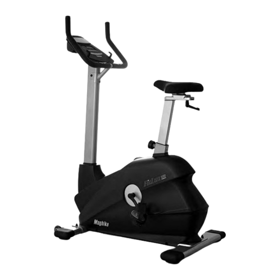
- Page 1 FitLux 5000 MAGNETIC BIKE Owner's Manual Made in Taiwan...
-
Page 2: Table Of Contents
INDEX IMPORTANT NOTICE . . . . . . . . . . . . . . . . . . . . . P . 1 ASSEMBLY PARTS LIST . -
Page 3: Important Notice
IMPORTANT NOTICE: THIS EQUIPMENT IS ONLY FOR HOME USE, NOT FOR COMMERCIAL PURPOSE. USER'S WEIGHT SHOULD BE LIMITED ONLY TO 150 KGS. 1 . Before proceeding into any type of exercise program, it is recommended that one should first consult a physician . 2 . -
Page 4: Assembly Parts List
Assembly No. Llist ASSEMBLY PARTS LIST 1 . MAIN FRAME . . . . . . . . . . . . 1 A . BOLT & WASHER & NUT . . .4+4+4 2 . -
Page 5: Assembly Instruction
Assembly Instruction Step 1. Step 2. Fix Front Stabilizer (5) on the Main Frame Fix Rear Stabilizer (2) on the Main Frame (1) and secure by Bolt, Washer & Nut (A) (1) and secure by Bolt, Washer & Nut (A) Step 3. - Page 6 Assembly Instruction Step 5. Step 6. Remove bolts from the front of Main Well connect the wires from Handlebar Frame . Be sure to keep Computer Wire Post (6) and Main Frame (1) . outside the frame for further assembly . Step 7.
- Page 7 Assembly Instruction hole A Step 9. Step 10. Use the string at hole A of Handlebar Attach Handlebar (3) to Handlebar Post Post (6) to tie up the Pulse Cable from (6) and secure by Screw & Washer (c) . Be Handlebar (3), then pull the string from top careful not to cut the Pulse Cable .
- Page 8 Assembly Instruction Step 13. Step 14. Plug in Audio Wire and attach Book Rack Screw in the Pedals (8) into cranks . to the Computer (7) Step 15. Step 16. Attach Decoration Cover (9) to the Main Plug Adapter (10) into the socket at the rear Frame (1) and fix by Screw (9) .
-
Page 9: Computer Instruction
Computer Instruction The monitor is designed for programmable magnetic bikes and introduced with the following categories: • Key Functions • About Displays • Operating Ranges • Things You Should Know Before Exercising • Operation Instructions • Key Functions There are total 6 keys including START/STOP, ENTER, MODE, UP, DOWN, and RECOVERY . - Page 10 Computer Instruction C . PROGRAM No .: Indicates the programs selected from PROGRAM 1 to PROGRAM 16 D . LEVEL No .: Indicates the level of loading selected from LEVEL 1 to LEVEL 16 . E . GENDER: Indicates the gender (Male or Female) selected . F .
- Page 11 Computer Instruction K . HEART RATE/BODY TYPE Display: Indicates only one value of HEART RATE or BODY TYPE displayed depending on the programs . L . LOADING Profiles: There are 10 columns of loading bars, and 8 bars in each column . Each column represents 3 minutes workout (without the change of TIME value), and each bar represents 2 levels of loading .
- Page 12 Computer Instruction • Things You Should Know Before Exercising A . The values calculated or measured by the computer are for exercise purpose only, not for medical purpose . B . The Variables May Need To Change In The Programs: Programs Variables P1 ~ P7...
- Page 13 Computer Instruction Program 5 (Ramp) Program 6 (Mountain) Program 7 (Random) Program 8 (Body Fat) Program 9 (Target H .R .) Program 10 (60% H .R .C .) Program 11 (75% H .R .C .) Program 12 (85% H .R .C .) Program 13 (User Setting) Program 14 (User Setting) Program 15 (User Setting)
-
Page 14: Operation Instructions
Computer Instruction E . Body Types: There are 9 body types divided according to the FAT% calculated . Type 1 is from 5% to 9% . Type 2 is from 10% to 14% . Type 3 is from 15% to 19% . Type 4 is from 20% to 24% . - Page 15 Computer Instruction Preset Programs: PROGRAM 2 to PROGRAM 7 are the preset programs . Press “ENTER” key to select TIME, DISTANCE, CAL and AGE . Then, press▲ or ▼ key to adjust the values . Users may exercise with different level of loading in different intervals as the profiles show .
- Page 16 Computer Instruction User Setting Programs: Program 13 to Program 16 are the user-setting programs . Users are free to edit the values in the order of TIME, DISTANCE, AGE, CAL and the level of loading in 10 intervals . The values and profiles will be stored in the memory after setup . After pressing “START/STOP”...
- Page 17 Computer Instruction LCD/LED W/ PROGRAM MONITOR TROUBLE SHOOTING GUIDE Symptom Possible Cause Solution You have the wrong Check that the Batteries or the Adaptor Specifications Adaptor or the wrong coincide with Intruction Manual Specifications . Batteries? The Mains Power switch is Check that the Mains Power is switched on and is The LCD turmed off?
- Page 18 Computer Instruction Symptom Possible Cause Solution The Computer is NOT Check that the Ear Clip Plug is FIRMLY inserted into the receiving a Pulse Computer . Signal . 1) The Ear Clip Pulse Sensors will NOT operate correctly if yours truly skin is extremely dry, dab a little water onto No Ear The Computer is your earlobe and try again .
- Page 19 Computer Instruction LCD W/PROGRAM MONITOR TROUBLE SHOOTING GUIDE Symptom Possible Cause Solution 1) Review the Assembly Instructions and check that all the Computer Plugs and Sockets are FIRMLY and correctly connected . 2) Review the Bike's Magnetic Resistance System to ensure that it is set correctly and the be at it can freely be adjusted .
-
Page 20: Exploded Drawing
Exploded Drawing... -
Page 21: Parts List
Parts List NO. DESCRIPTION Q'ty. NO. DESCRIPTION Q'ty. Main Frame Chain Cover – Right Flywheel Ø260 Chain Cover – Left Tension Cable Belt Spring Belt Wheel Support Bracket Screw M4x16mm Nut 3/8”x24UNF Screw M5x16mm Nutx3T 3/8”x24UNFx3T Crank Bolt M8x20mm Bearing #6000 Pedal - Right Plastic Wheel Pedal - Left... - Page 24 Factory: JIH KAO ENTERPRISE CO., LTD...
Need help?
Do you have a question about the 5000 and is the answer not in the manual?
Questions and answers