Sign In
Upload
Download
Table of Contents
Contents
Add to my manuals
Delete from my manuals
Share
URL of this page:
HTML Link:
Bookmark this page
Add
Manual will be automatically added to "My Manuals"
Print this page
×
Bookmark added
×
Added to my manuals
Manuals
Brands
Samsung Manuals
LCD TV
LE23R32B
Service manual
Samsung LE23R32B Service Manual
Hide thumbs
1
2
3
4
5
6
7
8
9
10
11
12
13
14
15
16
17
18
19
20
21
22
23
24
25
26
27
28
29
30
31
32
33
34
35
36
37
38
39
40
41
42
43
44
45
46
47
48
49
50
51
52
53
54
55
56
57
58
59
60
61
62
63
64
65
66
67
68
69
70
71
72
73
74
75
76
77
78
79
80
81
82
83
84
85
86
87
88
89
90
91
92
93
94
95
96
97
98
99
100
101
102
103
104
105
106
107
108
109
110
111
112
113
114
115
116
117
118
119
120
121
122
123
124
125
126
127
128
129
130
131
132
133
page
of
133
Go
/
133
Contents
Table of Contents
Troubleshooting
Bookmarks
Table of Contents
Service Manual
Product Specifications
Special Features
Spec Comparison
Option Specification
Exploded View and Parts List
Schematic Diagrams
Disassembly and Reassembly
Troubleshooting
Alignments and Adjustments
Factory Mode Adjustments
Entering Factory Mode
White Balance - Calibration
White Balance Adjustment
Method of Adjustment
Update Procedures
Block Diagram
Pcb Diagram
Wiring Diagram
Mainboard Layout
PIN Characteristic
Power Board Layout
Electrical Parts List
Circuit Descriptions
Block Description
Main Block
SMPS Board
Connection Panel
Remote Control
Installing the Stand
Installing the Wall Mount Kit
Reference Infomation
Technical Terms
Smps(Switching Mode Power Supply)
Pin Assignments
PC Display Mode
Timing Chart
Supported Modes
Panel Description
Safety Precautions
Fire and Shock Hazard
Product Safety Notices
General Servicing Precautions
Electrostatically Sensitive Devices (ESD) Precautions
Installation Precautions
Advertisement
Quick Links
1
Service Manual
2
Product Specifications
3
Special Features
4
Schematic Diagrams
5
Troubleshooting
Download this manual
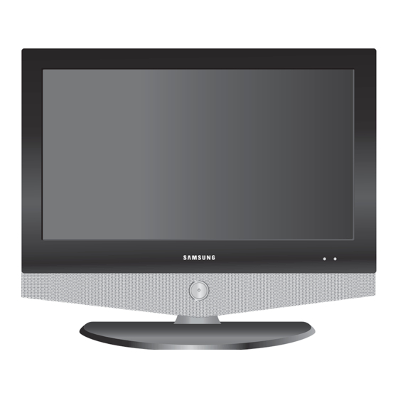
SERVICE
LCD-TV
LCD-TV
Chassis
Model
Manual
- HDMI/DVI, PC(Analog), 1 Component,
2 SCART, 1 Composite, S-Video, RF
- Brightness : 500cd/
- Contrast Ratio : 800:1
- Response time : 8ms
GRM23HEU
GRM26HEU
LE23R32B
LE26R32B
Features
Table of
Contents
Previous
Page
Next
Page
1
2
3
4
5
Advertisement
Table of Contents
Need help?
Do you have a question about the LE23R32B and is the answer not in the manual?
Ask a question
Questions and answers
Related Manuals for Samsung LE23R32B
LCD TV Samsung LE23R3 Owner's Instructions Manual
Samsung lcd tv owner's instructions (130 pages)
LCD TV Samsung LE23R3 Owner's Instructions Manual
(152 pages)
LCD TV Samsung LE23R3 Owner's Instructions Manual
(171 pages)
LCD TV Samsung LE23R7 Owner's Instructions Manual
(171 pages)
LCD TV Samsung LE23R71B Owner's Instructions Manual
(69 pages)
LCD TV Samsung LE23R71W Service Manual
(114 pages)
LCD TV Samsung LE23R41B Owner's Instructions Manual
(66 pages)
LCD TV Samsung LE23R81W Owner's Instructions Manual
(43 pages)
LCD TV Samsung LE32R86WD Owner's Instructions Manual
(66 pages)
LCD TV Samsung LE26R8 Owner's Instructions Manual
Lcd (507 pages)
LCD TV Samsung LE23R8 Owner's Instructions Manual
Lcd tv (451 pages)
LCD TV Samsung LE23R8 Owner's Instructions Manual
(173 pages)
LCD TV Samsung LE23R8 Owner's Instructions Manual
(286 pages)
LCD TV Samsung LE23R51B User Manual
(10 pages)
LCD TV Samsung LE23R86BD Service Manual
(140 pages)
LCD TV Samsung LE23R81BX Service Manual
Tft-lcd tv (83 pages)
This manual is also suitable for:
Le26r32b
Table of Contents
Save PDF
Print
Rename the bookmark
Delete bookmark?
Delete from my manuals?
Login
Sign In
OR
Sign in with Facebook
Sign in with Google
Upload manual
Upload from disk
Upload from URL


Need help?
Do you have a question about the LE23R32B and is the answer not in the manual?
Questions and answers