Table of Contents
Advertisement
Quick Links
Advertisement
Table of Contents
Troubleshooting

Related Manuals for Hitachi IJ UX


Summary of Contents for Hitachi IJ UX
-
Page 1: Service Manual
Service Manual HITACHI Printer Model UX Revision July. 1.2015 Version -... - Page 2 [ Revision of UX service manual ] Revision Chapter Revised Page Frist Edition...
-
Page 3: Table Of Contents
Contents 1. Introduction ································································································ 1-1 1.1 Safety precautions ················································································· 1-1 1.2 Structure of each part in the main body ······················································ 1-8 1.2.1 External views ················································································· 1-8 1.2.2 Main body internal ··········································································· 1-9 1.2.3 Print head ······················································································ 1-10 1.3 Installation ··························································································· 1-11 1.3.1 Power supply wiring ···········································································... - Page 4 2.19 Careful Cleaning Setup ········································································· 2-48 2.20 Logging data ······················································································· 2-51 2.21 Rescue soft ························································································ 2-57 2.22 Dimensions for Tapered-Printhead Printing ··············································· 2-59 3. Maintenance of controlling part······································································· 3-1 3.1 Construction of controlling part ································································ 3-1 3.2 Controller part ····················································································· 3-5 3.2.1 EZJ128 board (controller board) ·························································...
- Page 5 4.7 Circulation Unit Replacement Procedure ···················································· 4-16 4.8 Pump Parts Replacement ······································································· 4-18 4.9 Circulation Filter Replacement Procedure ···················································· 4-29 4.10 Ink/Makeup Reservoir Replacement Procedure ··········································· 4-30 4.11 Solenoid Replacement Procedure ···························································· 4-34 4.12 Troubleshooting when Fault Occurs in Viscometer ······································· 4-37 4.13 Print Head Replacement Procedure ··························································...
- Page 6 7. Attached Drawing ························································································ 7-1 7.1 Circulation system diagram ····································································· 7-1 7.2 Electrical Connection Diagram ································································· 7-4 7.3 Circulation sequence ··············································································· 7-6 7.4 Dimensions around charge electrode and deflection electrode ························· 7-8...
-
Page 7: Introduction
1. Introduction 1.1 Safety precautions Before starting the maintenance and inspection work of this printer, thoroughly read and understand the “safety precautions”. When explaining the product to customers at the time of the installation, fully explain the “safety precautions”. ● Before using the printer, thoroughly read the following safety precautions for optimum printer use. ●... - Page 8 SAFETY PRECAUTIONS (Continued) WARNING ● Ensure that there is no flame- or arc-generating device around the printer. The ink and makeup are both flammable and may cause fire. Fire can be generated by matches, lighters, cigarettes, heaters, stoves, gas burners, welders, grinders and static electricity. Arcs may be generated from open-type relays, switches, and brush motors.
- Page 9 ● The printer must be managed in compliance with all appropriate regulations. Check the supplementary manual (Ink) for the ink used. ● Use Hitachi approved consumables and periodic replacement parts. Using products that are not designated by Hitachi could cause s failure in certain functions.
- Page 10 SAFETY PRECAUTIONS (Continued) WARNING ● When charging a refill of ink or makeup, exchanging ink, or otherwise handling ink or makeup, take enough care not to spill ink or makeup. If you spill any ink or makeup by mistake, wipe it off neatly and promptly with wiping paper or something similar.
- Page 11 SAFETY PRECAUTIONS (Continued) WARNING ● When welding, keep enough space between the IJ printer and the welding work area to prevent the arc from starting a fire. Also, be sure to insulate the print head and IJ printer frame to keep the welding current from flowing to the control section of the printer, and to make a separate ground connection for the printer.
- Page 12 For information on handling, see the Safety Data Sheet (SDS). The SDS can be accesses from the following web site or from our sales office. URL http://www.hitachi-ies.co.jp/ijp ● If extraneous noise enters the printer, it may malfunction or break down.
- Page 13 SAFETY PRECAUTIONS (Continued) CAUTION ● When handling PC boards and electric parts, be careful of static electricity. PC boards and electric parts mount elements weak against static electricity. When handling PC boards and electric parts remove the static electricity by wearing a suitably grounded anti-static wrist band.
-
Page 14: Structure Of Each Part In The Main Body
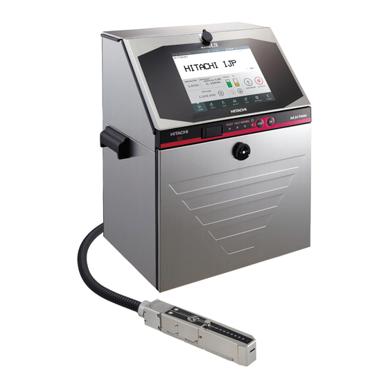
1.2 Structure of each part in the main body 1.2.1 External views (1)External views (UX-E,D) (2)External views (UX-B) -
Page 15: Main Body Internal
(2)External views (Rear side) 1.2.2 Main body internal [Appearance with inner cover (T) removed]... -
Page 16: Print Head
1.2.3 Print head 【UX-D、B】 【UX-E】 Air exhaust port 1-10... -
Page 17: Installation
1.3 Installation 1.3.1 Power supply wiring ! Caution •Use the proper plug. Be sure to ground properly. •Locate the equipment near an electrical outlet and arrange so it can be easily disconnected. •Use a power cable that is within the specified range. •Do not bundle the light electrical cable together with the power cable outside the unit so the light electrical signals (connection signals to the various signal [Applicable power cable]... - Page 18 1 Remove the inlet cover. (Fastening screws x 4) Inlet cover Precautions concerning electrical shock Be sure to unplug the power cable from the electrical outlet before performing work. 2 Mount the power cable in the inlet and mount the inlet cover. Caution •Be sure to mount the inlet Inlet base...
-
Page 19: Installation Procedure
1.3.2 Installation procedure Perform an installation work of the unit according to the following procedure at the unpacking. The cap of the compensating port is detach. Supply port cap Supply port cap (Caution 1) Ink reservoir Makeup reservoir Service personnel maintenance mode setup Service Manual procedure 2.1 Setting of service personnel... - Page 20 Adjustment of APH gain Service Manual (Touch screen operation, automatic acquisition) 2.3.4 Auto phase gain adjustment Setting of excitation voltage Technical Manual (Confirm the real printing state and the ink drop 6.10 Excitation V adjustment mode and then, set the excitation voltage) Readjustment of APH gain Service Manual (Touch screen operation, automatic acquisition)
-
Page 21: Maintenance Work
2. Maintenance work A screen for use in the maintenance work by a service personnel is described. 2.1 Setting of service personnel maintenance mode ● Set service personnel maintenance mode to perform maintenance work by service personnel such as system environment setup. Features of service personnel maintenance mode (differences with user maintenance mode) Function Contents... - Page 22 [Service personnel maintenance mode setup procedure] 1 Printing description screen is displayed. LOGIN 2 Press LOGIN. The login user select screen is displayed.
- Page 23 3 Select any user. The keyboard for inputting the password is displayed. Shift Enter 4 Input password “HIESmmdd” and press Enter. (mm: Month, dd: Day) Example: If date is December 31, 2015, input “HIES1231.” [Caution] The password “HIESmmdd” is a special password for enabling functions not disclosed to the customer.
-
Page 24: System Environment Setup
2.2 System environment setup ● The setting with respect to the system environment of the IJ printer is performed. ① ② Ink type Cable length ③ ④ Nozzle size Ink temperature correction ⑤ ⑥ Excitation frequency Excitation curve ⑦ ⑧ Ambient temperature upper limit Ambient temperature lower limit ⑨... -
Page 25: Adjustment/Operational Checkout
2.3 Adjustment/operational checkout 2.3.1 Excitation adjustment ● Adjust the drive conditions of nozzles. ● This adjustment is performed in a state other than the IJ printer “ready” state. ● Be sure to perform this adjustment in the case of replacing the board (EZJ126, 125, 128), or the nozzle (including the print head) or changing the ink type. - Page 26 3 Press Automatic adjustment. During automatic adjustment, “in progress” is displayed as the processing status. Proc. status: In progress The excitation voltage is automatically adjusted inside the IJ printer. The excitation voltage is gradually increased, and the adjustment is completed at 360 V ±...
- Page 27 When you press Manual adjustment and manually input the excitation voltage adjustment value, the excitation voltage value is increased or decreased. Check the waveform of TP14 (excitation voltage) on the EZJ125 board with an oscilloscope. For the position of the board and test pins, refer to “3.3.6 EZJ125 board.” [Stop Adjust./oper.
-
Page 28: Charging Voltage Confirmation
2.3.2 Charging voltage confirmation ● Voltage for confirmation of charging voltage is output for 3 minutes. ● Be sure to perform this confirmation when performing the board exchange (EZJ126 and 125). ●This confirmation is performed in a state the IJ printer “stop” state. 1 Press Adjustment/operational checkout on the maintenance menu. - Page 29 3 Measure TP12 of the EZJ125 board with an oscilloscope and make sure it is within the range of DC250V ± 15V. For the position of the board and test pins, refer to “3.3.6 EZJ125 board.” [Waveform of charge voltage confirmation] Charge voltage ←...
-
Page 30: Phase Margin Test
2.3.3 Phase margin test ● Perform the phase margin test of a nozzle. ● This test is performed to check the following: ① whether or not the nozzle is in a printable state (whether or not clogging is present) and ②... - Page 31 3 Select the setting values for print timing, print data and print phase. Setting items for phase margin test № Item Setting Contents value Button Prints each time Start printing is pressed. Print timing input Sensor Prints for each print sensor signal input. The printing conditions are automatically set as described below.
- Page 32 Example of [Print timing: Sensor] Adjust./oper. checkout [Ready Com=0 2015.07.07 12:45 <Phase margin test> Button input Sensor Print timing Print data For test Data to be displayed Print phase Automatic update Specified phase Printing starts upon signal from sensor. Print phase: X-phase (0-f) Abort Abort Dec.
-
Page 33: Auto Phase Gain Adjustment
2.3.4 Auto phase gain adjustment ● The gain of the auto phase detection voltage is automatically adjusted. ● Perform this adjustment after confirmation that the periphery of a gutter part within the nozzle head is not made dirty with ink or the like and the printing head cover is correctly fixed. ●... - Page 34 3 Press Automatic acquisition. During automatic acquisition, “acquisition” is displayed as the processing state. Proc. status: Acquisition Auto-phase detection voltage gain is automatically adjusted in the IJ printer. A target of the auto-phase gain value is about from “20” to “40” (65μm). 4 After the completion of the automatic adjustment, when the Back key is pressed, the auto phase detection voltage is output and therefore, confirm the waveform by an oscilloscope.
-
Page 35: Level Sensor Confirmation
2.3.5 Level sensor confirmation ● The liquid level and the operation of level sensors of the main ink tank, ink reservoir, and makeup reservoir will be confirmed. № Container type Level sensor Too high [OF] Initial level [1] / Sensor [1] Main ink tank Sensor [2] Sensor [3]... - Page 36 2 Press Level sensor confirmation. The level sensor confirmation screen is then displayed. Adjust./oper. checkout [Stop Com=0 2015.07.07 12:45 <Level sensor confirmation> WHITE <Main ink tank> <Ink reservoir> <Makeup reservoir> Too high [OF] Sensor [1] Sensor [□] detected undetected detected Sensor [2] detected Initial [1]...
-
Page 37: Heating Unit Confirmation
2.3.6 Heating unit confirmation ● The operation confirmation of heating unit is performed. ① Heating unit power ON/OFF. ● A display of an ambient temperature and a heating unit temperature is performed. ● Perform this operation confirmation in a state other than "Ready" state. 1 Press Adjustment/operational checkout on the maintenance menu. - Page 38 2 Press Heating unit confirmation . The Heating unit confirmation screen is displayed. Adjust./oper. checkout [Stop Com=0 2015.07.07 12:45 <Heating unit confirmation> Ambient temperature : 10 ( ) Heating unit temp. 20 ( ) Heating unit status : Deactivated Execution takes 5 minutes. Abort Abort Deactivate...
-
Page 39: Test Of Solenoid Valve/Pump
2.4 Test of solenoid valve/pump ● The operation confirmation of solenoid valve and pump is performed. ①Supply valve ②Replenishment valve (MV2) (MV1) ③Recovery valve ④Viscosity valve (MV3) (MV4) ⑤Circulation valve (MV5) ⑥Pressure relief valve (MV6) ⑦Makeup valve ⑧Cleaning valve (MV7) (MV8) ⑨Shutoff valve ⑩Pump... -
Page 40: Download
2.5 Download ● The function is used for upgrading the program. ● The program on the EZJ126 and EZJ128 boards is downloaded from the USB memory. ● A “USB memory containing system data” is required. ● The function is executed with the IJ printer in “Stop” state. ●... - Page 41 3 Press Download on the second page of the maintenance menu. The download screen is then displayed. Download [Stop 2015.07.07 12:45 Com=0 Downloaded from(USB memory) Controller software 03.00 Print controller software M 03.00 Print controller software S 03.00 Print controller ROM data 03.00 CG font data 03.00...
-
Page 42: Calibration Of Viscometer
2.6 Calibration of Viscometer 2.6.1 Calibration of viscometer ●The calibration of viscometer is to determine the “coefficient” inherent in the equipment. ●Calibrate the viscometer when installing equipment. Normally, calibrating it once is enough. However, calibrate the viscometer again when changing the ink type, and also calibrate a new viscometer after replacement. -
Page 43: Operation Test Of Viscometer
3 The measurement is completed in four minutes, and coefficient (calculated value) will be displayed. [Standard value of the viscometer calibration] 1200 to 2200 *The value stated above is a reference. There will be no problem even If the coefficient value displayed is other than stated above as long as data of Plunger falling time fall within a similar range. -
Page 44: Circulation System Environment Setup
2.7 Circulation system environment setup ● Select whether or not the ink concentration is controlled based on results of the viscosity measurement. ● Perform these settings at “Stop” state. Setting items of Circulation system environment setup screen Item Selection Contents The ink concentration is controlled by the dot count control without measurement of the ink viscosity. -
Page 45: System Reset
2.8 System reset ●S et the set values on the “Printing data”, “User pattern” and “Maintenance” screens to the values of initial condition. ● Perform this function when the EZJ128 board or the EZJ126 board is replaced in a state allowing no backup. -
Page 46: Backup
2.9 Backup ● Print data and user data are backed up on a USB memory. ● Backup data can be copied on an IJ printer. ● You can select the type of data when copying to the IJ printer. ● The copying method is replacing the content of USB memory as they are (overwrite copy). -
Page 47: Unit Information
2.10 Unit information ● Displays/changes unit TYPE-FORM, serial No., Icon type, login information and ink type. Item Contents TYPE-FORM Displays TYPE-FORM. Serial No. Displays Serial number. Icon type Select the Icon type on the display. Viscosity coefficient Ink viscosity coefficient can be changed. Ink and makeup usage Whether or not to display a warning when ink and makeup time limit control... - Page 48 1 Press Unit information on the maintenance menu. If in the user maintenance mode, set to the service personnel maintenance mode on the login user selection screen. For information on changing to the service personnel maintenance mode, refer to “2.1 Setting of service personnel maintenance mode.” The unit information screen is then displayed.
-
Page 49: Handling Of The Warning "Product Speed Matching Error", Etc
2.11 Handling of the warning “Product Speed Matching Error”, etc. (user environment setup) ● Displays items of user environment setup screen that can be set in the service personnel maintenance mode. Items that can be set in the service personnel maintenance mode (user environment setup screen) №... - Page 50 Arabic number “2” print CG example (characters size in figure is “12 x 16”) < Method 1 > < Method 2 > ● You can enhance printing quality by increasing the “character height” setting value and decreasing distance between printing head and print object, rather than decreasing the “character height”...
- Page 51 [Example 2] The print items are “NOT” added in units of “Column” up to the numbers specified. (24 items are set.) Before Change After Change 1Line/1Column + 3Lines/1Column 1Line/1Column + 3Lines/7Columns + 1Line/2Columns (4 items) (24 items) Column1 Column2 Column1 Column2 Column8 Column9 Column10...
- Page 52 1 Press User environment setup on the maintenance menu. If in the user maintenance mode, set to the service personnel maintenance mode on the login user selection screen. For information on changing to the service personnel maintenance mode, refer to “2.1 Setting of service personnel maintenance mode.” The user environment setup screen is then displayed.
- Page 53 [Third page] User environment setup [Stop Com=0 2015.07.07 12:45 Start Arabic pattern variation Manual method1 method2 Minimum character height (0-50) HOME Disable Enable Signal detection in target sensor filtering Disable Enable Print Overlap Fault Check Prev. Next set- set- tings tings Disable Enable...
-
Page 54: Language Registration
2.12 Language registration ● This function is to register screen languages. ● Register display language for the IJ printer from the “USB memory containing system data”. ● Keyboard type for character input can be selected by input mode. Input mode Input mode Contents Default... - Page 55 [Note] ● Do not leave from the printer until download procedure is complete then confirm the select language screen display. The download has succeeded when select language screen redisplay. Download had not succeeded when the select language screen did not redisplay or power failure happened during download procedure.
-
Page 56: Fault / Warning Log Management Code
2.13 Fault / Warning log management code ● This function displayed code number in the Fault/Warning log screen. Fault/Warning Log Code Table Code Code Message name Message name Ink Low Fault Detector Position Improper Main Ink Tank Too Full Target Sensor Timer Out Deflection Voltage Fault Target Spacing Too Close Ink Replenishment Time-out... - Page 57 Code Code Message name Message name External Communication Error 005 External Communication Error 006 Parts Life Expired External Communication Error 007 Parts Life Expired External Communication Error 008 External Communication Error 009 Ink Level Sensor Broken 2 External Communication Error 010 Makeup Level Sensor Broken 2 External Communication Error 011 Ink Low Warning 2...
-
Page 58: Software Option Setup
2.14 Software option setup 2.14.1 Software option setup for UX-D,E ●Use this function when setting up software options to IJ printer. ● In order to set up options, EZJ129 board / EZJ130 board and a memory card (IJP system-data is stored) are required. For information on installing EZJ130 board, refer to “3.3.12 EZJ130 board (Software option control board)”. -
Page 59: Standard Communication Option Setup For Ux-B
5 Change the option to set up to “Enable”. Option setup [Stop Com=0 2015.07.07 12:45 Disable Enable 04 Special communication A Disable Enable 05 External signal A HOME Disable Enable 08 Barcode reader connection 13 LAN communication Disable Enable 07 MOBA Disable Enable none... -
Page 60: Upgrade Option Setup For Ux-D
2.15 Upgrade option setup for UX-D ● Functional upgrade is available with inserting upgrade key. ● The possible steps for upgrade is depending on the number of upgrade-key. < Available upgrade steps > Number of Upgrade step Upgrade-Key Up to 4 steps ●There are five upgrade groups. - Page 61 [Procedure to upgrade function using upgrade key for UX-D] 1 Turn off the power and install the upgrade-keys on EZJ126 board. 2 Turn on the power. 3 Press Upgrade function setup at the second page of the service maintenance work screen. If Prev.
-
Page 62: Time Of Preparing For Printing (Ux-D,E Only)
2.16 Time of preparing for printing (UX-D,E only) ● Set time between after the print target detection signal is input and printing. Time between after print target detection signal is input and printing Model Set Value Time of preparing UX-B Standard only Approx. - Page 63 Print specifications screen Print specifications [Stop Com=0 2015.07.07 12:45 1st screen 2nd screen 3rd screen Start Manual None Encoder Product speed matching HOME (1/1~1/999 Enter denominator.) Pulse rate div. Factor 0 0 1 0 0 0 0 0 Line speed [m/min.] Input ‘0’...
-
Page 64: Touch Screen Setup
2.17 Touch screen setup ● Touch screen setup items with service mode as following. Items of Touch screen setup with service mode № Item Setting Contents To the left Cursor move to right to left when input the text. Arabic input mode To the right Cursor move to left to right when input the text. -
Page 65: Expiration Date Management Of Ink And Makeup
2.18 Expiration date management of ink and makeup 1.Overview When the ink or makeup bottle which passed the expiration date were to be opened for use, or when the ink or makeup passed estimated replacement time after opening or ※ recommended expiration date , fault of “Ink Shelf Life Information”... - Page 66 (2) Input lot number Lot number (example: G01D-1) is indicated on the label of ink or makeup. By inputting this lot number on Unit information screen, year and month of manufacture of Ink or makeup is calculated within IJP, and makes it possible to manage the expiration date.
- Page 67 (4) Fault (a) Fault occurrence condition When Expiration date management for ink and makeup is set to Enable, the fault of “Ink Shelf Life Information” or “Makeup Shelf Life Information” is output under conditions below. № Fault output condition 1 At startup, [Present ≧...
-
Page 68: Careful Cleaning Setup
When this function of “Careful-Cleaning Stop” is set to Enable, please hand out to the customer 2- page instruction of “Hitachi IJP - Model UX Careful Cleaning Instruction Manual” which is attached herewith and provide an explanation of “Operation and Precautions” properly. - Page 69 Hitachi IJP - Model UX Careful Cleaning Instruction Manual This is the function to clean the nozzle carefully when shutting down IJP. Please read the instructions below and execute “Careful cleaning” function. 1. Operation 1.1 Operation procedures of “Careful cleaning” shutdown process...
- Page 70 2. Precautions The ink concentration will get lower compared to that of the regular shutdown process since the shutdown process of “Careful cleaning” will use extra amount of makeup. (It will consume about the double amount of makeup of the regular shutdown process. Please pay extra attention as stated below.
-
Page 71: Logging Data
2.20 Logging data - Log the operating conditions to investigate the fault and warning condition. - Log files are copied to the below holder when backup function is performed in the Service personnel maintenance mode. List of Log files File name Contents Logging timing ALARM.TXT... - Page 72 (2) Automatic ink replenishment data (AUTOSPLY.TXT) [Example] Initial level Makeup ink (High- replenishment replenishment replenishment Control speed Ambient Viscometer Cumulative (for dot (to an initial (to an initial № Date Start time sequence machine) Mode temperature temperature Pressure print count Dot count count) level) level)
- Page 73 ● Automatic ink & makeup replenishment sequence Viscosity Waiting for Makeup Printing measurement defoaming replenishment replenishment replenishment (30 minutes) (for dot count) (to initial level) (10 minutes) Step B2 Step C1 Step C3 Step B1 Step C2 Step B2 is for Pigment ink only. <Log timing>...
- Page 74 (3) Viscosity control data (INKVISCO.TXT) [Example] Adjustment Initial level of viscosity (High- Average at (High- Control Control speed № Date Time №1 №2 №3 №4 №5 falling time Temperature Standard Viscosity speed code info. machine) 1 2011/7/7 0:29:23 1.58 1.58 1.58 1.57 1.57 1.57 2.22 0 Normal...
- Page 75 (4) Circulation system control data (SEQUENCE.TXT) [Example] Aborted № Date Start time Finish timeCode Sequence name Result step № info1 info2 info3 info4 7:05:29 1 2011/7/7 0:02:09 160 Eject ink B 7:06:56 2 2011/7/7 1:53:16 208 Noclean-stop 8:06:56 3 2011/7/7 0:05:35 80 Nozzle backwash 9:07:45...
- Page 76 Code number and sequence name Code Sequence name Code Sequence name Power turned on time Excitation V-ref. (Max) Current time change Unmatched language key Select message Upgrade recovery Fault/warning log clear Print interval mode Set Viscosity Solvent recovery system Excitation V Ink Drop Charge Rule Serial number changer Cable length change...
-
Page 77: Rescue Soft
- Use this function when the IJ printer does not start up during turn on procedure. - Use the Rescue soft which is prepared by Hitachi. - This function will initialize all registered data and settings, ensure reinstall all data and settings with “Back up”... - Page 78 2 Resetting Items. Confirm as following items after rescue procedure. Item After rescue Back up data Serial number Same before rescue Language1 : English, Select Languages Language2 : none, Reinstall from language select screen. Input mode : 1 Option setup Not supported Usable (Back up data) Print data...
-
Page 79: Dimensions For Tapered-Printhead Printing
2.22 Dimensions for Tapered-Printhead Printing ●When it is necessary to place the printhead close to the conveyer or when the milk carton is printed, refer to the following figures for the reference dimensions for the tapered-printhead printing. 1)In case that Tapered Printhead is placed close to Belt Conveyor The bottom height of printing area, measured from the Belt conveyor *1. - Page 80 Previous Model Model UX <Upright> <Inverted> (*2) (*2) Milk Carton <Upright> (*2) Milk Carton Milk Carton (*2):Print distance(From printing surface to print head.) ●[Precautions on printing close to print target] When the printing is made close to the print target, it is possible for the printhead cover to get stained inside and outside by the ink splash bounced back from the print target.
-
Page 81: Maintenance Of Controlling Part
3. Maintenance of controlling part 3.1 Construction of controlling part The controlling part is mainly composed of a controller part of performing the display and the data management, an engine part of performing the printing control and the circulation system control, I/O part of performing external signal control, and interior of inlet cover at primary power side. - Page 82 [Engine part (cover-opening state)] High voltage power supply Multiple power supply Battery DC fan EZJ125 EZJ126 EZJ132 [I/O part (cover-opening state)] EZJ119 board (Available as option) Fixing screw (M3x2) EZJ127 board IJP LAN UNIT Fixing screw (M3x2) (Available on some models as option) Fixed with plastic holder Caution When opening the maintenance door in a state where the surface of the main body is...
- Page 83 [Interior of Inlet cover part (cover-opening state)] Caution against electric shock AC power is supplied to interior of the inlet cover. Be sure to cut off the power supply and wait for at least 10 seconds to pull the power cable out of the outlet before opening the cover.
- Page 84 [Component table of the Controller circuit board and electric parts by models] Y---Use, N---No use, OP---Option [Controller circuit board] Parts name Function UX-D/E UX-B EZJ126A ASSEMBLY MPU board UX - D/E EZJ126B ASSEMBLY MPU board UX -B EZJ125 ASSEMBLY Nozzle Drive board EZJ128 ASSEMBLY Controller board EZJ127A ASSEMBLY...
-
Page 85: Controller Part
3.2 Controller part - With regard to the electric parts/control board of the controller part, the functional outline, the list of the check point and the note at the replacement are described. 3.2.1 EZJ128 board (controller board) [ Function] - Preparation/management of print data is performed. - Program, user data and environment setup data are stored. - Page 86 Caution As for the copy data function, the user mode and the service personnel maintenance mode are different. When replacing the EZJ128, put it into the service personnel As for the System maintenance mode and then perform the backup. reset, see “2.8 System -User mode: User data (printing data (Note 1), substitution rules, user patterns) reset”.
- Page 87 EZJ128 board external views Connector for battery connection C55+ Fixing screw (3 locations) Fixing screw (3 locations) Connector for EZJ 114 board Connector for EZJ126 board Connector for IC34 Connector for LCD harness Connector for touch panel Without Fixing screw Fixing screw (3 locations) Caution...
-
Page 88: Battery
3.2.2 Battery [Function] - The back up battery for the RTC (Calendar IC) on the EZJ128 board - 2 batteries are used per 1 machine. Backup batteries for EZJ126 board and EZJ128 board. With respect to the setting of date and time, refer to the Instruction manual “6.2 [Note at the replacement] setting the Date and... - Page 89 Caution - When replaced with an incorrect type of battery, the battery is in danger of exploding. Be sure to replace the battery with the one specified by parts list. - When battery is disposed of, insulate it using tape, etc. (1) If mixed with other metal or battery, uninsulated battery may cause heating, fire or explosion.
-
Page 90: Lcd
3.2.3 LCD [Function] - The LCD panel for screen display. [Note at the replacement] - Be sure to turn off the power when replacing the panel. - After replacing, insert the flexible flat cable that connects the LCD to EZJ128 board to right places. - Page 91 (3) How to lock the actuator To lock the actuator, press it downward. When locking the actuator, apply the pressure to the direction indicated by arrow (to the direction of inner side of the connector) to avoid the separation of rotary shaft from the actuator. [LCD external view Touch panel Board mounting plate...
-
Page 92: Touch Panel
3.2.4 Touch panel Function] -Input system for display screen operation. [Note at the replacement] - Be sure to turn off the power at replacement. - After replacement, insert the connectors to right places. Caution when inserting or extracting touch panel connection cable When inserting the touch panel connection cable into the connector of the EZJ128 board, hold both sides of the reinforced... -
Page 93: Engine Part
3.3 Engine part - With regard to the electric parts/control board of the engine part, the functional outline, the setting of the switch, the list of the check point and the note at the replacement are described. 3.3.1 EZJ126 board (MPU board) [Function] - Performs printing control, circulation system control, nozzle control (charge voltage, excitation voltage, auto phase and the like) and communication. - Page 94 (13) Recover the data from the USB memory by using the copy data function. (From the USB memory to the IJP) With respect to the replacement procedure of Caution EZJ125, refer to “3.3.6 EZJ125 board”. As for the copy data function, the user mode and the service personnel maintenance mode are different.
- Page 95 [EZJ126 board external views] Connector for power supply TP321 “PGND” Connector for battery connection Connector for EZJ130 Not mounted on UX-B TP774 TP1427 “Encoder-N” “Print-in-progress” TP323 “SGND” TP787 “Sensor-N” Not mounted on UX-B Connector for Connector for EZJ125 board model key Connector for Two hexagonal spacers Connector for...
- Page 96 3.3.2 Battery [Function] - The back up battery for the RTC (Calendar IC) on the EZJ126 board - 2 batteries are used per 1 machine. Back up batteries are for EZJ126 board and EZJ128 board. [Note at the replacement] Caution - Before replacing the battery, be sure to turn off the power.
-
Page 97: Ezj126 Board (Mpu Board)
[Note at the replacement] - In the event of breakage of model key, the key needs to be replaced. Contact to Hitachi factory. - Do not install model key that are removed from other machines. - Before the replacement, be sure to turn off the power. - Page 98 [Procedure for function addition using upgrade key for UX-D/E] (1) Turn off the power and turn on the power with upgrade key installed on EZJ126. (2) Input a special password for service maintenance mode on Select login user menu. With respect to the setting (3) Select Upgrade screen on the second page of the service maintenance screen.
-
Page 99: Ezj125 Board (Nozzle Drive Board)
3.3.6 EZJ125 board (Nozzle drive board) [Function] - Control of nozzle (charging voltage control, excitation voltage, APH detection, PTC control and the like) is performed. [Setting of switch/check point/LED display and the like] - Setting of switch Nozzle size 65µm DSW1 Mark Set both bits up. - Page 100 (3) Remove the connectors from CN4, CN6 and CN7. (4) Remove the EZJ125 board. *) At first, remove the fixing screws (2 positions). Then as the drawing below, push the hook of fixing spacer of EZJ125 board and pull up the EZJ125 board. (Two spacers) EZJ125 board Push the hook Spacer for fixing...
-
Page 101: Ezj127 Board (I/O Board)
3.3.7 EZJ127 board (I/O board) [Function] - The I/F signal with the conveyer is connected. Output signal: Ready, Fault, Warning, Printing-in-progress/Print-complete, On-line, With respect to the wiring, Universal output 1, Universal output 2 refer to Technical manual Input signal: Print target detector, Print stop, Reciprocative printing, “4 Connection of signals”. - Page 102 [Setting of switch/check point/LED display and the like] - Setting of switch [SW1] Set content Default Bit 1 Setting is performed according to the specification of the encoder. Bit2 (Refer to the setting by types of the specification described below.) Bit3 Setting is performed according to the specification of the print target detector .
- Page 103 - Check point/LED Reference Name Content number Floating GND Reference ground of external part (conveyer side) photo coupler insulation circuit LED1 Print target detector When the Print target detector is ON, it is lighted. input LED2 Printing stop input (PNP) When the printing stop signal input (PNP) is ON, it is lighted.
- Page 104 [EZJ127A board external view] Terminal block: TB1 Two fixing screws Two fixing screws LED1 – LED23 Lot number: (Last digit: A) [EZJ127B board external view] Terminal block: Two fixing screws TB1 (13 pins) Two fixing screws LED1, LED4, LED19 Lot number: (Last digit: B) [Usage for the External connection terminal block 1 (TB1)] - Applicable cable size : AWG26 to 16 (Φ0.5to 1.3)
- Page 105 [Procedure to add the option for UX-B (change to EZJ127A board)] (1) Turn off the power and be sure not to supply the electric power to the wires connecting to TB1. (2) Remove the connectors and change to EZJ127A board. (Two fixing screws) (3) Insert the connectors and perform the setting of SW1 and 2.
- Page 106 [External communication (RS-232C)] - Connector for external communication (RS-232C) is mounted on EZJ127A board. - Using signals: SD, RD and SG - Signal specification (NC: Unconnected) Name Input/Output Remarks Pin number (NC) Unconnected Input Output Connected to DSR on IJ printer Ground Connected to DTR on IJ printer Connected to CTS on IJ printer...
- Page 107 3-27...
- Page 108 3-28...
-
Page 109: Ezj132 Board (Ink Circulation Module Connection Board)
3.3.8 EZJ132 board (Ink circulation module connection board) [Function] - Electrical connection board between control part and ink circulation module part. [Notes in case of the board replacement] - Before replacing the board, be sure to turn off the power. - Use a φ2 lenghe:160mm Philips screw driver. - Page 110 [Replacement procedure of EZJ113 board] (1)Turn off the power and wait for more than 10 seconds. Then pull the plug out of socket. (2)Open the maintenance door and remove the ground wire. (3) Remove the fixing screws (4 positions) and remove the side cover and remove the ground wire.
-
Page 111: Ezj114 Board (Led / Sw Board)
3.3.10 EZJ114 board (LED / SW board) [Function] - LED display of Power, Ready, Fault, Warning, and Start / Stop switch [Notes in case of the board replacement] - Before replacing the board, be sure to turn off the power. - After replacing the board, be sure to joint connectors to right places. - Page 112 [Connection to the external connection terminal block (EZJ119A -TB2) ] Name Remarks 30VAC/0.5A or 30VDC/1A Ready 30VAC/0.5A or 30VDC/1A 30VAC/0.5A or 30VDC/1A Fault 30VAC/0.5A or 30VDC/1A 30VAC/0.5A or 30VDC/1A Warning 30VAC/0.5A or 30VDC/1A Terminal specification: M4 [Setting of switch 3] The ready output selector switch (SW3) is used to enable or disable the ready signal output.
-
Page 113: Ezj130 Board (Software Option Control Board)
3.3.12 EZJ130 board (Software option control board) [Function] - Input / output control board when software option is used. (Option for UX-D/E) [Notes in case of the board replacement] - Before replacing the board, be sure to turn off the power. - After replacing the board, be sure to joint connectors to right places. - Page 114 [ Setting of SW/Check point/Display of LED etc ] [SW1] ●Setting of input signal Calendar stop signal Reserve input SW1 Mark Mark Both of bits are put Set the right bit to on the up position the bottom. 3-34...
-
Page 115: Ezj129 Board (Software Option Terminal Board)
3.3.13 EZJ129 board (Software option terminal board) [Function] - Input / output terminal board when software option is used. (Option for UX-D/E) [Notes in case of the board replacement] - Before replacing the board, be sure to turn off the power. - After replacing the board, be sure to joint connectors to right places. - Page 116 [Specification of RS-232C communication connector] - External equipment is connected to the EZJ129 by serial communication of RS-232C. -Signal used : RD,SD,DTR,SG,DSR,RTS,CTS -Wiring ( NC is No connection ) Pin number Name Input / Output Remarks (NC) No connection Input Output Output Ground...
- Page 117 [Connection to external connection block (TB3)] Name of signal Input / Output Remarks NPN/PNP NPN/PNP Interface - Signal ground Signal notifying Completion of signal input Output -NPN / PNP can be selected by SW7 Signal during calendar Updating Output Strobe signal Input - NPN / PNP can be selected by SW8 -...
- Page 118 [ Setting of SW ] ●Setting of SW [SW4] Description Default Bit 1 Reserve ( Set to OFF ) Bit 2 Sets host communication (Set to OFF) Bit 3 Sets host communication (Set to OFF) Bit 4 Switches the filter constant of strobe signal (capacitance) ON : 0.047 (uF) + 2.2(uF) OFF : 0.047 (uF) Bit 5...
- Page 119 [SW6] Description Default Bit 1 Reserve ( Set to OFF) Bit 2 Bit 3 Bit 4 Bit 5 Bit 6 Bit 7 Bit 8 [SW7] signal connection is NPN/PNP. Setting it according to the reserve input (Default setting is put on the up position.) NPN I/F PNP I/F Mark...
- Page 120 -Check points / LED- Reference Name Contents number Floating GND Reference ground of external part (conveyer side) photo coupler insulation circuit LED1 Reserve input LED2 Reserve input LED3 Reserve input LED4 Calendar stop /Reserve input1 (NPN) LED5 Calendar stop /Reserve input1 (PNP) LED6 Data message number signal When the data message number signal bit 0...
- Page 121 Reference Name Contents number LED26 Data message number signal When the data message number signal bit 10 bit 10(NPN) input (NPN) is ON, it is lighted. LED27 Data message number signal When the data message number signal bit 10 bit 10(PNP) input (PNP) is ON, it is lighted.
- Page 122 3-42...
-
Page 123: Multiple Power Supply
3.3.14 Multiple Power Supply [Function] - AC input: AC100 ~ 240V (50/60Hz) DC output: +3.4V, +5.1V, +12V, -12V, +24V [Note at the replacement] - In a few seconds after turned off the power, residual voltage is remaining on the parts of multiple power supply. - Page 124 (3) Disconnect the AC input connector of multiple power supply inside the side cover. [Inside of side cover] < UX-D/E > < UX-B > Ground wire Ground wire (Yellow/green (Yellow/green spiral) spiral) EZJ113 board AC input connector (4) Open the maintenance door. (5) Remove the wire harness from the wire clamp put on the high voltage power supply protective cover.
-
Page 125: High Voltage Power Supply
3.3.15 High Voltage Power Supply [Function] - Deflection voltage output : DC 5.7kV Max. Charge signal source voltage output : DC500V Caution against an electric shock The high voltage power supply has a portion where high voltage is applied. In order to avoid an electric shock, be sure to turn off the power before access the high voltage power supply. -
Page 126: Dc Fan
3.3.16 DC fan [Function] - Input voltage: DC 24V For air agitation to uniform the controller part air temperature [Note at the replacement] - When replacing the DC fan, be sure to turn off the power. - Be sure to joint the connector. - When installing the DC fan, pay attention to the mounting direction of NP (name plate) and harness. -
Page 127: Tup-I (For Ux-D/E Only)
3.3.17 TUP-I (for UX-D/E only) [Function] - Input voltage:DC24V; Output specification:RJ-45 connector; Ethernet Communication. - TUP-I is Ethernet communication unit, using IJP communication library. [Precautions for replacement] - Be sure to turn off the main power switch before starting replacement. - Ensure to insert connectors. -
Page 128: Ijp Lan Unit (Ilu) (Option)
3.3.18 IJP LAN Unit (ILU) (Option) [Function] - Input voltage: DC 24V Output specification: RJ-45 connector, Ethernet communication [Note at the replacement] - When replacing the ILU, be sure to turn off the power. - Be sure to joint the connectors. Straight slot screws (M2.5) [ILU external view]... -
Page 129: Rfid Reader
3.3.19 RFID reader [Function] - Read Ink ID or Makeup ID from IC tag on Ink/Makeup cartridge bottle. Select Login user ID by reading IC card as a consequence call the print data of the user. [Precaution for RFID reader replacement] - When you replace RFID reader, be sure to turn the main power off. - Page 130 (5) Peel off FB sheet. (6) Unscrew three (3) fixing screws for Front beam, and then remove Front beam. [Caution] When you remove Front beam, DO NOT pull RFID reader harness by force. Fixing screws (3 pieces) for Front beam Front-beam sheet Front beam (7) Unscrew two (2) fixing screws for RFID reader cover, and then remove...
-
Page 131: Electrical Connection Diagram
3.3.20 Electrical Connection Diagram 3-51... - Page 132 3-52...
- Page 133 - Regarding the wire harness clamping position inside the maintenance cover, refer to following list. [UX model wire harness list] DWG No. Parts No. Name 3J83N95321 Card connector UX 2N4ZL2142A LED harness UX 1N4ZE0065A Controller harness UX 2N4ZL2138A Relay harness UX 3N4ZM5783A AC harness assembly B 2N4ZH9186A...
-
Page 134: Maintenance Of Circulation System
4. Maintenance of Circulation System 4.1 Structure of Circulation System 4.1.1 General Structure of Circulation System The general structure of the circulation system is shown in the following figure. Using an open/close type door (unit door) as a partition, the system is roughly divided into an ink circulating area (the front side of the equipment) and a driving part area (the rear side of the equipment). - Page 135 4.1.2 Access to the parts on the front side of the equipment 1 Remove the Inner cover (T). 2 Remove the fixing screws(2) (2 pieces) and draw the reservoir unit out to the front halfway by supporting “a” part (4 places) with both hands. Reservoir Unit Rock pin guard Inner cover (B)
- Page 136 <Cautions when Recovery filter base is removed> When the Recovery filter base is removed, please confirm the following points as described in the figure below. ・Please confirm the Twist-Locks (Cable Fastener) are securely fastened to the Recovery filter connecting tubes. Recovery filter connecting tubes (2 pieces) Twist-Lock (Cable Fastener, 2 pieces)
- Page 137 4.1.3 Access to the parts on the rear side of the equipment (1) Access method from the front 1 Perform “4.1.2 Access to the parts on the front side of the equipment” and pull the reservoir unit out. 2 Remove the fixing screws (2 pieces) of the unit door and open the unit door. [Caution] Take care not to cause the tubes to be caught.
- Page 138 (2) Access method from the rear 1 Remove fixing screws (11 positions) of the rear cover and detach it. Rear cover These two screws can remain loosened.
- Page 139 4.2 Main Ink Tank Maintenance 4.2.1 Structure of Main Ink Tank Front Ink Level can roughly be confirmed by viewing the Drain Tube. [CAUTION] When Air Trap is observed, conduct Air removal until no Air Trap is observed. Check the Level surface. The Air Trap will not interfere with the operation of the printer.
-
Page 140: Main Ink Tank Replacement Procedure
4.2.2 Main Ink Tank Replacement Procedure 1 Drain the ink in the main ink tank. (Execute “Ink Drainage” or drain ink from the drain tube.) 2 Turn off the power supply. 3 Perform “4.1.2 Access to the parts on the front side of the equipment” and pull out the reservoir unit. - Page 141 9 Remove the fixing screws (2 positions) and remove the Makeup reservoir. Makeup reservoir Fixing screws Remove the Solenoid cable from the hook on the Inner cover (B). Hook Solenoid Cable Inner cover (B) [Caution] Pay attention NOT to pinch the Solenoid Cable while above work is implemented. 11 Remove the fixing screw (1 position) and take out the main ink tank.
- Page 142 13 Remove the fixing screws (2 positions) and take out the inner cover (B) Main ink tank Inner cover (B) Plug ICU joint (UX-E only) Fixing screws 14 Clean the portion stained with ink and then install the main ink tank in reverse order of the procedures above.
-
Page 143: Pressure Reducing Valve Replacement Procedure
4.3 Pressure Reducing Valve Replacement Procedure 1 Perform “Pressure relief”. 2 Perform the procedures described in “4.1.2 Access to the parts on the front side of the equipment”. 3 Remove Fastening screw M4x12 (2 positions: upper right and lower left of Pressure reducing valve) and Pressure reducing valve itself. -
Page 144: Joint Structure And Handling
4.4 ICU Joint Structure and Handling When removing the tube during the maintenance work, loosen the tube lock beforehand. The ICU joint shall be removed only when damaged. Procedures for installing the tube ICU joint Tube lock 1 Pass the tube through the tube lock. 2 Insert the end of the tube into the end of the ICU joint. -
Page 145: Solenoid Valves Replacement Procedure
4.5 Solenoid Valve Replacement Procedure ・ Parts inside the solenoid valve (diaphragm, etc.) cannot be replaced separately. In the case of part failure, replace the entire solenoid valve. ・ The coil mold of the solenoid valve (black resin portion) is not resistant to solvents. Do not immerse the coil mold in solvent. - Page 146 5 Remove the fixing screws (2 positions) of the solenoid valve. "Caution": Put wiping paper under the solenoid valve to provide for an ink drip. Orange Yellow Purple Fixing screws (2 Positions) Blue Green Gray Brown 6 Clean the portion stained with ink and then install the new solenoid valve in reverse order of the procedures above.
-
Page 147: Pressure Sensor Replacement Procedure
4.6 Pressure Sensor Replacement Procedure 1 Perform “Nozzle Backwash”. (Till stopped automatically without sucking the makeup into the gutter) 2 Turn off the power supply. 3 Perform “4.1.3 Access to the parts on the rear side of the equipment”. (The reason is that the connector is located on the rear side of the equipment.) 4 Remove the connector of the pressure sensor. - Page 148 6 Remove the fastener fastening the pressure sensor to the joint and remove the pressure sensor by pulling. [Caution] Put wiping paper under the Pressure sensor for ink dripping. Joint Pressure sensor Fastener 7 After cleaning the portion stained with ink, wet the new O-ring with makeup and mount on the joint.
-
Page 149: Circulation Unit Replacement Procedure
4.7 Circulation Unit Replacement Procedure 1 Perform “Ink drainage” and then “Pressure relief”. 2 Turn off the power supply. 3 Perform “4.1.2 Access to the parts on the front side of the equipment” and draw out the reservoir unit. 4 Perform “4.1.3 Access to the parts on the rear side of the equipment” “(1) Access method from the front”... - Page 150 7 Disengage the connectors of the electrical parts (15 positions) (motor, solenoid valves (8 positions), pressure sensor, viscometer (3 positions), level sensor and float sensor). 5 positions 1 position 8 positions 1 position 8 Remove the fixing screws at that fix the circulation unit (4 positions). The circulation unit can be removed.
-
Page 151: Pump Parts Replacement
4.8 Pump part replacement 4.8.1 Pump Unit Replacement Procedure 1 Perform “Ink drainage” to “Pressure relief”. 2 Turn off the power supply. 3 Perform “4.1.3 Access to the parts on the rear side of the equipment”, “(1) Access method from the front” and open the unit door. [Caution] Be careful not to catch the tubes. - Page 152 6 Pull out connectors(6 positions) toward the front, which were disengaged in item 5 above. Then, remove the tubes (4 positions) and remove the screws (2 positions) that fix the pump unit on the door. (Remove the tube from the ICU joint, which is shown by dashed line. Remove the other tubes (3 positions) by loosening the tube locks.
- Page 153 8 Remove the fixing screws (8 positions) which connects both the upper part and the lower part of the circulation unit. The pump unit can be removed. "Caution": Put wiping paper under the pump unit to provide for an ink drip. Pump Unit ICU fixing plate Fixing screws (8 positions)
- Page 154 4.8.2 Drive unit replacement procedure 1 Perform “Ink drainage” to “Pressure relief”. 2 Turn off the power supply. 3 Perform “4.1.3 Access to the parts on the rear side of the equipment”, “(1) Access method from the front” and open the unit door. [Caution] Be careful not to catch the tubes.
- Page 155 6 Holding the drive unit by hand, remove the fixing screw (6 pieces), and remove the drive unit Fixing screws Fixing screws Pump unit 7 Remove the Drive unit from the Pump unit. [ Caution] When the Drive unit is removed, the springs on the Pump head (4 pieces) are freed causing the internal parts (diaphragms) elongated.
- Page 156 4.8.3 Pump head replacement Perform “Ink drainage” to “Pressure relief”. Turn off the power supply. 3 Perform “4.8.2Drive unit replacement procedure” and remove the drive unit . Remove the fixing screws (2 positions) and remove the pump head. [Example] The following figure below indicates the case of the circulation pump head removal.
- Page 157 Clean the portion stained with ink and then install the new pump head in reverse order of the procedures above. [Caution] Make sure to use new O-rings. (2 pieces) Be careful not to cause the O-ring to fall off or pinched. Refer to the figures below for identifications of 4 kinds of pump heads.
- Page 158 4.8.4 Motor replacement 1 Turn off the power supply. 2 Perform “4.1.3 Approach to the parts on the rear side of the equipment”, “(1)Access method from the front” and open the unit door. [Caution] Be careful not to catch the tubes. 3...
- Page 159 5 Install the new motor in reverse order of the procedures above. Pump unit Motor Fixing screw (4 pcs) Board shall look down. [CAUTION] Beware of Motor Rotation! When checking the motor with IJP door opened, watch the motor rotation and/or being caught by motor.
- Page 160 4.8.5 Gear replacement 1 Turn off the power supply. 2 Referring to 4.8.2 Drive unit replacement procedure and remove the drive unit. [Caution] When the drive unit is removed, the springs on the pump head (4 pieces) are freed causing the internal parts (diaphragms) elongated. To avoid this, put the drive unit back to its place approximately within 30 minutes.
- Page 161 Rotate the gear counterclockwise and remove the gear. Turn counterclockwise Gear Install the new gear in reverse order of the procedures above. When installing, coat the gear teeth with the silicone grease. (Use Silicone Grease G501 made by Shin-etsu Chemical Co., Ltd.) 4-28...
- Page 162 4.9 Circulation Filter and Makeup Filter Replacement Procedure 1 Perform the procedures described in “4.1.2 Access to the parts on the front side of equipment” and pull the Reservoir unit forward. Replacement of circulation filter 2 Rotate the nut of the circulation filter and pull it out. 3...
- Page 163 4.10 Ink Reservoir/Makeup Reservoir Replacement Procedure 4.10.1 Ink Reservoir replacement 1 Drain ink from the ink reservoir. Connect the recovery tube to waste bottle. Execute “Reservoir Ink-Drainage” and drain the ink from the ink reservoir. [Caution] In case that the ink doesn't come out from the ink reservoir even when "Reservoir InkDrainage"...
- Page 164 7 Remove the fixing screws (2 positions) and take out the inner cover (INK). Inner cover (INK) Fixing screws 8 Clean the portion stained with ink and then install the new ink reservoir in reverse order of the procedures above. [Caution] When installing the Ink reservoir, put the hook of the Ink reservoir into the hole of the Reservoir base first.
- Page 165 4.10.2 Makeup Reservoir replacement 1 Drain makeup from the makeup Reservoir. Execute “Reservoir Makeup Drainage” and drain the makeup from the makeup reservoir. [Caution] In case that the makeup doesn't come out from the makeup reservoir even when "Reservoir Makeup Drainage" is executed, which may be caused by malfunction of the part such as the solenoid valve or the pump, remove the makeup reservoir in the step [5] below and drain the makeup into a beaker out of the makeup reservoir's opening for attaching the sensor block.
- Page 166 7 Remove the Fixing screws of Inner cover(SOL) (2 positions) and remove the Inner cover (SOL). Inner cover (SOL) Fixing screws 8 Clean the area stained with ink and the install the new Makeup Reservoir in reverse order of the procedures above. [Caution] When installing the Makeup Reservoir, out the hook of the Makeup reservoir into the hole of the Reservoir base first.
-
Page 167: Solenoid Replacement Procedure
4.11 Solenoid Replacement Procedure The replacement solenoid (color of wiring:Orange) can be used for both solenoids of Ink-side and makeup-side. [Caution] ・Please do not mix up solenoid connectors of ink-side and makeup-side when you connect them. ・After replacement, please cofirm that the solenoid on ink-side and/or Makeup-side operates properly. - Page 168 6 Remove the Fixing screws(1) (2 pieces) and remove the solenoid unit. 7 Remove the Fixing screws(2) (2 pieces) and remove the solenoid cover. 8 Remove the Fixing screws(3) (2 pieces each) of the Solenoid to be replaced, and remove the solenoid. Fixing screws(1) Fixing screws(3) Solenoid unit...
- Page 169 12 Installing the new Makeup Reservoir in reverse order of the procedures above. [Caution] When installing the Makeup Reservoir, confirm that the Solenoid Cable is routed to the hook of the inner cover(B). When installing the Makeup Reservoir, out the hook of the Makeup reservoir into the hole of the Reservoir base first.
-
Page 170: Troubleshooting When Fault Occurs In Viscometer
4.12 Troubleshooting when Fault Occurs in Viscometer Follow the troubleshooting steps below when the error occurs in viscometer. [Caution] If “Viscosity Reading Instability” or “Viscosity Readings Out of Range” is occurred , the IJP will automatically switch to the dot count system and operate. (1) Viscosity Reading Instability ・... - Page 171 (D) Pull out the viscometer IN-side tube (mark G) from viscometer. [Caution] The ink in tube will slightly drip: Fit wiping paper to the end of tube. No reverse flow of ink will occur inside the viscometer. (E) Immediately lift the end of removed tube higher than the level of liquid in the main ink tank, and then keep this for at least 10 seconds to return the ink in tube to the main ink tank.
- Page 172 4.12.2 Disassembling and washing viscometer 1 Remove the three setscrews from viscometer cover, and then remove the cover. 2 Place the viscometer upside down while applying wiping paper to the plunger, and then remove the plunger. (Let all of the ink remaining in viscometer seep out to the wiping paper.) 3 Make sure that no ink remains in viscometer, and then pull out the cylinder.
- Page 173 4.12.3 Viscometer assembly procedure 1 Replace the cylinder, and then insert the plunger. Handle the plunger with tweezers making sure that no dust adheres to the surface of plunger. 2 Set the collar to cylinder, paying extra attention to its orientation (with the convex up). 3 Make sure that the O-ring is set in the viscometer cover, and then assemble the cover into the viscometer case.
- Page 174 4.12.5 Replacing thermistor 1 Remove the viscometer from circulation unit, referring to item 4.12.1. 2 Remove the screw (1 pc) holding the thermistor fixing plate, and then replace the thermistor. [Caution] When installing the new thermistor, moisten the O-ring with makeup to prevent it from being damaged.
-
Page 175: Print Head Replacement Procedure
4.13 Print Head Replacement Procedure 1 Carry out “Ink drainage.” 2 Turn off the power supply. 3 Open the maintenance cover and remove the print head connectors (5 locations) in the control area. High voltage line FG line Remove the side cover and FG line of the print head. 【The inside of a side cover】... - Page 176 6 Remove the tubes (4 pieces) which were just removed, from the plastic clamps on the main body wall. Also, the Twist-Locks (2 pieces) as shown in the figure below shall be removed. [Note] Please pay extra attention NOT to lose the removed Twist-Lock (Cable Fastener). For reassembling, refer to <Cautions when Recovery filter base is removed>...
- Page 177 11 Widen the Claws of Head H Clamp assembly and remove it from the harness of the print head. Head H Clamp assembly FG line (Green) High voltage line (White) 14-wire cable (Black) [the thickest cable] Excitation line (Black) Cable Mark No. 5 Video signal line(Black) APH line(Black) Claws...
-
Page 178: Troubleshooting Procedure For The Circulation System
4.14 Troubleshooting Procedure for the Circulation System Perform “(1) Fault locating and repairing method” for each trouble symptom. For the items marked * in “Probable Cause”, perform “(2) Fault locating method for the control system/circulation system” to make sure that the control system is normal, and then perform the repair work. - Page 179 Check method Symptom Probable cause Repairing method The supply pump Follow the same descriptions as those of “Ink does not eject". malfunctions. When “Open” is Replace or repair the executed on “Solenoid solenoid valve (MV1). * MV1 Valve/Pump Test” Refer to “4.15 Repairing malfunctions.
- Page 180 Symptom Probable cause Repairing method Check method The recovery Follow the same descriptions as those of “The supply pump pump malfunctions ". malfunctions. When “Open” is Replace or repair the executed on solenoid valve (MV3). The solenoid * MV3 “Solenoid Refer to “4.15 valve Valve/Pump Test”...
- Page 181 Symptom Probable cause Repairing method Check method The supply pump Follow the same descriptions as those of “Ink does not eject”. malfunctions. When “Open” is Replace or repair the executed on solenoid valve (MV6). The solenoid “Solenoid Charging or * MV6 Refer to “4.15 valve Valve/Pump Test”...
- Page 182 (2) Fault locating method for the control system/circulation system (a) When the pump motor and all the solenoid valves are not operated, the multi-power supply (24 V system) is abnormal. (b) If the electrical parts (pump motor, solenoid valves, and pressure sensor) are not operated, i,e., any case other than above, make the following checks first.
-
Page 183: Repairing Method When The Circulation Route Is Dry Or Sticks
4.15 Repairing Method When the Circulation Route Is Dry or Sticks 4.15.1 How to restore operation when solenoid valve seizure is stuck. 1 Turn off the power. 2 Perform “4.1.3 Access to the parts on the rear side of the equipment” and open the unit door. - Page 184 4.15.3 Repairing method for the makeup pump 1 Remove the tube connecting block of makeup reservoir, and then connect the cleaning bottle to the pipe of pipe N. (You can apply pressure more easily by putting a tube between the pipe and the cleaning bottle.) Cleaning bottle Pipe...
-
Page 185: Maintenance Work Of Intake Fan Unit
4.16 Maintenance work of intake fan unit 4.16.1 Structure of Intake fan unit Intake fan cover Thumbscrew Air filter Intake fan unit assembly Intake fan Intake fan cover assembly 4.16.2 Replacement of Intake fan unit 1 Turn off the power. 2 Loosen the thumbscrew and remove the Intake fan cover. - Page 186 4 Remove the Fastening screws (4 locations) of the Intake fan unit assembly. Fastening screws (4 locations) Intake fan unit assembly 5 Disengage the Intake fan harness, connector and remove the Intake fan unit assembly. Intake fan harness connector 冷却ユニットクミ Intake fan unit assembly Intake fan cover assembly 6 Remove the Fastening screws (4 locations) of Intake fan cover assembly.
-
Page 187: R Air Filter Replacement Procedure
4.17 R Air filter Replacement Procedure [Replacement interval] - The replacement interval of the R air filter is about 4800 hours as standard, but the actual replacement interval varies by the printer’s operating environment condition. Replace the R Air filter at the same time with the air filter (in every two times). - Page 188 5 Reset the time of the R air filter to 0 on the “Parts usage time management” screen. 4-55...
- Page 189 4.18 Check on Exhaust Duct dripping The exhaust contains the vapor of makeup and it will be liquefied when cooled down. Depending on the IJP’s installation environment, there will be a case that there is a big difference between IJP’s inside temperature and the operating temperature. When IJP is installed or when IJP is serviced at periodical maintenance, please check the items below: (1) Is there any wiring routed around the exhaust duct, such as the power cord, the electrical...
-
Page 190: Circulation System Cleaning Of Printer Which Uses Ethanol-Based Ink
4.19 Circulation system cleaning of printer which uses Ethanol-based ink The Ethanol-based ink could be influenced by the environment where the printer is installed, and it is likely to cause clogging of the filter compared to MEK-based ink. The periodical replacement of the filters, and the periodical cleaning of the circulation system with Makeup for MEK-based ink shall be conducted in order to maintain proper operation of the printer. - Page 191 (7) Cleaning of Ink reservoir, Main ink tank and Viscometer. 1 If the ink reservoir is stained with ink, use makeup (S100A) to clean it. 2 Refer to “4.2.3 Removal method of the Main ink tank lid” for overhaul of the main ink tank. 3 Refer to “4.12.1 Viscometer removal procedure”...
-
Page 192: Cleaning Of Dedicated Path For Low Volatilization System (Ux-E Only)
4. 20 Cleaning of dedicated path for Low volatilization system (UX-E only) • Periodical cleaning of the dedicated path for Low volatilization system shall be conducted in order to maintain proper operation of the printer. (It is recommended the cleaning is conducted at the time of periodical maintenance of the printer.) 1 While cleaning is conducted, the liquid will drip from the Printhead and the Exhaust duct. - Page 193 3 Inject makeup into the Exhaust tube (Piping [5]) using Hand pump and clean the path. • Inject the makeup until the liquid drips from the Air exhaust port. Printhead cover locking thumbscrew Air exhaust port Charge electrode Negative deflection electrode Gutter Nozzle orifice Positive deflection electrode...
- Page 194 6 Inject makeup into the Exhaust tube (Piping [1]) using Hand pump and clean the path. • Inject the makeup until the liquid drips from the Air exhaust duct. 7 Disconnect the Exhaust tube (Piping [1]) which is connected to the Hand pump, and reconnect the tube to the Main ink tank.
-
Page 195: Print Head Related Maintenance
5. Print head related maintenance 5.1 Print head rough configuration (1)UX-B/D Coupling Heating unit connector Shutoff valve (MV9) connector Cover switch connector Shutoff valve Heating unit (MV9) Air purge tube Nozzle Cover switch excitation connector Video signal Coupling cover line APH board Nozzle Nozzle ground... - Page 196 (2)UX-E Coupling Heating unit connector Shutoff valve (MV9) connector Heating unit Cover switch connector Mist Shutoff valve collector (MV9) Air purge tube Nozzle excitation connector 3P Coupling Cover switch Gas/liquid cover separator APH board Video signal line Nozzle Nozzle ground Charge electrode Negative deflecting...
-
Page 197: Cable Running Direction
5.2 Cable running direction The cable running direction can be changed as shown in the following figure. The customer should not attempt to run the cable himself. The cable should be run by a service technician. 1 Remove the 4 fastening screws. Pull out the coupling approximately 10 mm. -
Page 198: Gutter Configuration And Replacement Method
5.3 Gutter configuration and replacement method 5.3.1 Gutter configuration Following configuration differs according to the type of machine O-ring 1.6 With membrane 5.3.2 Replacement method 1 Remove the 2 fastening screws 2 The gutter base and APH shield plate come off. APH shield plate *Note The packing consists of a combination of 2 types. -
Page 199: Mgv Filter Replacement
5.4 MGV filter replacement 1 Depressurize the printer. 2 Remove the head cover and the heater cover. MV9 filter 3 Remove the lead wire Air purge tube of the nozzle and air purge tube. Lead wire Coupling cover 4 Remove Screw A(1 location) and remove the coupling cover. - Page 200 MV9 6 Lift the MV9. 7 (1)Remove the nozzle-IN joint from the MV9 filter then remove O-ring 3.9. MV9 filter Nozzle-IN joint Fix a new MV9 filter and O-ring 3.9. Perform the assembly after dipping the O-ring in makeup, and confirm that the O-ring does not jump out of the hole.
-
Page 201: Shutoff Valve (Mv9) Replacement
5.5 Shutoff valve (MV9) replacement 1 Depressurize the printer. 2 Remove the head cover and the heater cover. 3 Disassemble the shutoff valve connector. Shutoff valve connector Air purge tube 4 Remove the nozzle lead wire and the air purge tube. Lead wire Coupling cover 5... - Page 202 MV9 7 Take up the shutoff valve(MV9), remove the makeup in joint and remove the shutoff valve (MV9). When the O-ring (P2.2) is remained at the heating unit, remove it. 8 (1)Put the MV9filter, O-ring3.9, O-ring2.2and O-ring1.7 into the respective holes of the joint part.
-
Page 203: Heating Unit Replacement
5.6 Heating unit replacement 1 Depressurize the printer. 2 Remove the head cover and the heater cover. Air purge tube 3 Remove the nozzle lead wire and the air purge tube. Lead wire 4 (1)Remove Screw A(1 location) and remove the coupling cover. Coupling cover (2)Remove the heating unit joint presser foot and remove the ink-supply tube(E) - Page 204 MV9 6 Remove the shutoff valve.(MV9) (Refer to 5.5 Replacement of shutoff valve) 7 Remove the 4 fastening screws of the heating unit. Heating unit Remove the rear cover (8 screws) 8 Remove the connector and remove Heating unit the heating unit. Connector 9...
-
Page 205: Aph Board Replacement
5.7 APH board replacement 1 Remove the head base rear cover APH board Fastening 2 Remove the APH board fastening screw. 3 Slide approximately 4 mm. 4 Pull out. Connector Connector 5 Remove the connectors (2 locations). APH sensor 6 Remove the APH sensor Gutter base ... -
Page 206: Nozzle Replacement
5.8 Nozzle replacement 1 Depressurize the printer. 2 Remove the head cover and the heater cover. 3 Remove the excitation line from the 3P coupling cover and disconnect the connector. Nozzle out joint Nozzle Nozzle excitation connector Coupling cover 4 Remove the coupling cover fastening screw (B), the ground wire fastening screw (D) and charge electrode fastening screw (C). - Page 207 6 Hold the tip of nozzle and remove the nozzle pulling it obliquely upward. 7 Attach a new nozzle and fix the nozzle setscrew, (2 locations), the nozzle IN joint presser foot (shutoff valve side), the nozzle OUT joint and the excitation connector. “Caution”...
-
Page 208: Nozzle Orifice Cleaning
5.9 Nozzle Orifice Cleaning 1) Detergent to use for an ultrasonic cleaning 2)Procedures of the cleaning Nozzle Clogging or Ink Stream Bent occurred. The ultrasonic cleaning with the Weak-Alkali Detergent is effective for the foreign objects of the nozzle orifice Eject the makeup *1 and confirm which it is hard to remove with MEK or the ink stream position if it is at... - Page 209 3) The efficient way to use the ultra-sonic cleaning machine The efficient way to use the ultra-sonic cleaning machine for ultra-sonic cleaning of the nozzle orifice 1: How to find the optimum cleaning position When the orifice is cleaned by the ultra-sonic cleaning machine, the aluminum foil can be used as a good trial sample to find the right position to place the nozzle orifice in the machine.
-
Page 210: Mist Collector Maintenance(Applied Ux-E Only)
5.10 Mist collector maintenance(applied UX-E only) 1 Remove head cover and heater cover. 2 Unscrew the fixing screw of coupling cover, and then remove the coupling cover. Fixing screw of coupling cover (1 location) Mist collector 3 Remove the nut of the mist collector, and then using tweezers, take out O-ring and the filter from inside. -
Page 211: Thermistor Replacement
5.11 Thermistor replacement 1 Remove the four (4) fixing screws, and then pull out the coupling to the direction of the arrow. Fixixng screws (2 pieces) Coupling Fixixng screws (2 pieces) 2 Remove the banding band and the packing. [Caution] Before removing the banding band and the packing, put a mark on the tube by a tape, etc. - Page 212 3 Remove the thermistor connector. White wire Red wire 4 Take the used thermistor out from the coupling, and then replace it with the new one. Used thermistor New thermistor 5 Attach the new banding band and the packing, and then reassemble all the removed parts in reverse order of the procedures above.
-
Page 213: Deflecting Base Replacement Procedure
5.12 Deflecting Base Replacement Procedure When the LED protection glass is damaged or when the deflection base is extremely dirty and cannot be rid of the abnormality even after cleaning, it is necessary to replace the deflection base. Perform it by using the following procedure. 1... - Page 214 8 Coat the high-voltage electrical power lines setscrew part with silicon rubber according to the following procedure. ①Fill the top and bottom of the ring terminal with silicon rubber, using a dispenser. Caution a) Hold the head as shown below in order to prevent the silicone from High-voltage line terminal running.
- Page 215 ② Heat the filled part by a warm air of a drier (500W equivalent) for 7 to 8 minutes and cure the surface. Caution : Keep the drier 50 to 100mm away so as not to deform the tube by keeping it too close.
-
Page 216: Head Base Replacement Procedure
5.13 Head base Replacement Procedure When damaging the head base, the head base must be replaced. Perform it by the following procedure. 1 Remove the head cover and heater cover. 2 Remove the nozzle described in the item 5.7. 3 Remove the deflecting base described in the item 5.11. - Page 217 11 Attach the heater, the deflecting base, the heater spacer packing and the deflecting base packing. 「Caution」Push the deflecting base against the arrow direction Heater Deflecting base Heater Heater spacer packing Deflecting base packing 12 Dispose the APH tube part group on the head base and connect it to the recovery tube. 13...
-
Page 218: Head Cable Replacement Procedure
5.14 Head Cable Replacement Procedure Refer to 「4.13 Print head replacement procedure」for separatingto console and head cable. 1 Caution against an electric There is work of opening the maintenance door. In order to avoid an electric shock, be sure to turn off the power before access the high voltage power supply. 2... -
Page 219: Troubleshooting
6. Troubleshooting 6.1 Troubleshooting List Name Remarks Subsection Faults – Ink-stop type 6.2.1 Ink Low Fault 6.2.2 Main Ink Tank Too Full 6.2.3 Deflection Voltage Fault 6.2.4 Ink Replenishment Timeout 6.2.5 Ink Drop Charge Too Low 6.2.6 System operation error C/M/S 6.2.7 Deflection Voltage Leakage 6.2.8... - Page 220 Warning conditions (printing continuously performed) 6.4.1 Excitation V-ref. Review, Excitation V-ref. Review 2 6.4.2 Viscosity Reading Instability 6.4.3 Viscosity Readings Out of Range 6.4.4 High Ink Viscosity 6.4.5 Low Ink Viscosity 6.4.6 Battery Low M 6.4.7 Calendar Content Inaccurate Refer to the Technical External Communication Error nnn manual “5.7.
-
Page 221: Faults - Ink-Stop Type
6.2 Faults – Ink-stop type 6.2.1 Ink Low Fault Ink Low Fault Open the maintenance cover. Uncap the ink reservoir and add ink. Is there ink in the ink reservoir? Is the fault cleared by pressing the Clear key? ● Turn OFF the power. ●... - Page 222 6.2.2 Main Ink Tank Too Full Main Ink Tank Too Full Is the initial-level sensor Open the maintenance cover. Check the initial- Is the ink main tank full Has the Main Ink level sensor Tank Too Fill fault of ink? connection again and frequently occurred? correct it if necessary.
- Page 223 6.2.3 Deflection Voltage Fault Deflection Voltage Fault Is the EZJ125 board CN6 connector or high-voltage power supply output connector disconnected? Disconnect the connector and then Connect the connector. reconnect it. Does the printer become ready for printing? Replace the high-voltage power supply unit.
- Page 224 6.2.4 Ink Replenishment Time-out Ink Replenishment Time-out Press the Reset key to clear the fault and execute “Ink refill”. Then restart the printer. Does the “Replenishment Time-out” fault recur? Does the MV2 (Replenishment valve) operate on the solenoid valve/pump test screen? Does the MV2 operate when the connector of the other Replace the connection...
- Page 225 ② Does the initial-level sensor operate? Is the EZJ126 board CN13 or EZJ132 board CN1, 3 connector disconnected? Connect the connector. Disconnect the connectors, then reconnect them (3 connectors). Does the initial-level sensor operate? Is the connection harness conducting? Replace the harness. Is the fault cleared by power-on reset? Replace the EZJ126 board.
- Page 226 6.2.5 Ink Drop Charge Too Low Ink Drop Charge Too Low Is the nozzle clogged or the ink stream bent? Pour a cleaning solution over the orifice plate surface to clean it, then allow it to thoroughly dry. If the problem is not fixed: Are the charge electrode Execute the “Nozzle...
- Page 227 6.2.6 System Operation error C / M / S System Operation error C / M / S Is the IJ printer connected to its dedicated ground? Properly establish the ground connection. Are the nozzle head and IJ printer main body insulated from the other equipment? Ensure that the print head and printer main body are...
- Page 228 6.2.7 Deflection Voltage Leakage Deflection Voltage Leakage Does the ink stream enter the center of the Is the ink or makeup gutter? deposited on the deflection electrodes and their surrounding sections? Adjust the ink stream position. Is any foreign matter deposited between the Thoroughly remove deflection electrodes?
- Page 229 Does the IJ printer become ready when you start it by pressing the Startup key with the high-voltage power supply unit output connector disconnected? Replace the high-voltage power supply unit. Resume the Is the alarm issued? operation. Replace the EZJ125 board. Resume the Is the alarm issued? operation.
- Page 230 6.2.8 Makeup Replenishment Time-out Makeup Replenishment Time-out Does the MV7 (Makeup valve) operate on the solenoid valve/pump test screen? Does the MV7 operate when Replace the connection the connector of the other harness operating solenoid valve is ① connected to MV7? The makeup does not flow into the main ink tank from the makeup reservoir when Pump...
- Page 231 6.2.9 Makeup Low Fault Makeup Low Fault Open the maintenance cover. Is the makeup reservoir charged with the makeup? Uncap the makeup reservoir and add the makeup. Turn OFF the power. Can the abnormality be cleared by pressing the Clear key? Is the sensor connector disconnected? (See the overall wiring...
- Page 232 6.2.10 Ink Heating Unit Too High Ink Heating Unit Too High ▪ Clear the fault. ▪ From the maintenance screen, place *) Refer to the following caution. the heating unit in the operating mode. *) ▪ Restart the IJ printer. See Section “6.5.8, No ink ejection Does the ink jet out? from nozzle.”...
- Page 233 6.2.11 Multi DC Power Supply Fan Fault Multi DC Power Supply Fan Fault Is the EZJ126 CN2 connector or Is the multiple power supply fan multiple power supply CN4 running? connector disconnected? Connect the connector. Replace the EZJ126 board. Is the problem fixed? Replace the multiple power supply 6-15...
- Page 234 6.2.12 Charge Voltage Fault Charge Voltage Fault Remove the print head cover. Pour the makeup over the charge electrode area to clean it. ・Allow the print head surface to adequately dry. ・Clear the fault. ・Restart the IJ printer. Does the printer become ready? Replace the EZJ125 board.
- Page 235 6.2.13 No Ink Drop Charge No Ink Drop Charge Is the ink stream Refer to “6.5.8 No ink being ejected from ejection from nozzle.” the nozzle? Refer to “6.2.5 Ink Drop Is the nozzle clogged or Charge Too Low”. the ink stream bent? Refer to “6.2.5 Ink Drop Is the gutter section Charge Too Low”.
- Page 236 6.2.14 Ink Heating Unit Temperature Sensor Fault Ink Heating Unit Temperature Sensor Fault Disconnect the EZJ125 board CN7 connector and reconnect it. ▪ Clear the fault. ▪ From the maintenance screen, place the heating unit in the operating mode. *) *) Refer to the following caution.
- Page 237 6.2.15 Memory Fault C/M/S Memory Memory Fault M/S Fault C Does the fault recur Does the fault recur upon power-on reset? upon power-on reset? Do the system reset by rescue soft Do the system reset by rescue soft Does the fault recur? Does the fault recur? Replace the EZJ126 board.
- Page 238 6.2.18 Ink Heating Unit Over Current Ink Heating Unit Over Current Is the PTC resistance measured (between the EZJ125 board TP3 and TP15) lower than 23 Ω? Replace the heating unit. ▪ Clear the fault. ▪ From the maintenance screen, place *) Refer to the the heating unit in the operating mode.
- Page 239 6.2.19 Ambient Temperature Sensor Fault Ambient Temperature Sensor Fault Disconnect the EZJ125 board CN7 connector and reconnect it. Does the fault recur? Replace the print head. Does the fault recur? Resume the Replace the EZJ126 board. operation. 6.2.20 Cooling Fan Fault Cooling Fan Fault Disconnect the EZJ126 board CN21 connector and reconnect it.
- Page 240 6.2.21 Pump Motor Fault Pump Motor Fault Pull out and insert the connector ・CN13 of the EZJ126 board ・CN1 and CN3 of the EZJ126 board ・pump motor Does the fault recur? Replace the pump motor. Does the fault recur? Does the connection harness have electrical continuity? Replace the connection harness...
- Page 241 6.2.22 Viscometer Ink Temperature Sensor Fault Viscometer Ink Temperature Sensor Fault Disconnect and reconnect the following connectors. ▪ EZJ126: CN13 ▪ EZJ132: CN1, 3 ▪ Thermistor relay harness connector Does the fault recur? Replace the thermistor of Viscometer. Does the fault recur? Replace the EZJ126 board.
- Page 242 Does the fault recur? Resume the It is necessary to change the model key. operation. Contact your local Hitachi sales office with the unit serial number and model name. 6.2.25 Language-key Fault Language-key Fault Does the fault recur after disconnect...
- Page 243 6.2.26 Charge Voltage Too Low Charge Voltage Too Low Clear the fault. Place the printer in The “Ready” state. Does the fault recur? Replace the EZJ125 board. Does the fault recur? Replace the high-voltage power supply. Does the fault recur? Replace the EZJ126 board.
- Page 244 6.2.27 Circulation Route Pressure Is High <Conditions an alarm is issued> An alarm “Circulation Route Pressure Is High” is displayed on the screen when the ink is being ejected and the ink pressure is not lowered at MV5 “ON/Open” step in the following sequences 1), 2) and 3).
- Page 245 6.2.28 Makeup Level Sensor Broken (3) Makeup Level Sensor Broken (3). Go to “Level sensor confirmation” screen and check if all sensors contained in Makeup reservoir work properly. Turn OFF power. Any disconnection or poor connection is found Remove the connector once and at CN13 connector on reconnect it EZJ126 board or CN1 or...
- Page 246 6.2.29 Ink Drop Charge Fault Ink Drop Charge Fault Is the setting of DSW2 of Correct the setting of DSW2 of EZJ125 board correct? EZJ125 board. Does the fault recur? Replace the EZJ125 board. Does the fault recur? Replace the high voltage power supply. Does the fault recur? Replace theEZJ126 board.
-
Page 247: Faults - Print-Stop Type
6.3 Faults – Print-stop type 6.3.1 Ink Drop Charge Too High Ink Drop Charge Too High Clean the gutter section and its surrounding area with a cleaning solution. (When using carbon type ink, remove the deflection plate, Is the gutter charge plate and gutter, then clean the mounting base surface as mentioned on section soiled? - Page 248 6.3.2 Barcode Short On Numbers Barcode Short On Numbers Input the fixed number of character for EAN-13, EAN-8, UPC-A, UPC-E Resume the operation. Fixed character number When country code is input When country code is input on edit message screen on print format screen EAN-13 EAN-8...
- Page 249 6.3.4 Count Overflow Count Overflow In case of count multiplication printing, set the count condition so that the digit number of integer part of multiplication result (*) is not exceeded the input count character. *) Multiplication result = “Count value” x “Count multiplier” Resume the operation.
- Page 250 6.3.6 Print Head Cover Open Print Head Cover Open Is the print head cover removed? Properly install the print head cover. Is the print head cover completely closed? Completely close the print head cover. Is the magnet inside the head cover damaged or missing? Properly install the magnet.
- Page 251 6.3.7 Improper Sensor Position Improper Sensor Position Is the repeat printing function required? Is there an excessive clearance between the print head and print target detector? Is the “Repeat count” is set to “0000” from the print Decrease the specifications screen? clearance between the print head and print target...
- Page 252 6.3.8 Target Sensor Fault Target Sensor Fault Is the target sensor fault function required? From the printing specifications screen, select a “Target sensor timer” setting of “0000”. Is the “Sensor out timer” setting is greater than necessary for the sensor normal ON time? Select a setting that is greater than necessary.
- Page 253 6.3.9 Target Spacing Too Close Target Spacing Too Close Are there more than four workpieces (print targets) between the sensor and print head? Decrease the clearance between the sensor and print head and reduce the number of workpieces between the sensor and print head to four or less.
- Page 254 6.3.11 Blank Print Items Blank Print Items Does any print item consisting of Blank characters alone exist? Adjust the print contents so that print items consisting of Blank characters only no longer exist. Resume the operation. 6.3.12 Excessive Format Count Excessive Format Count Are there more than nine columns having...
- Page 255 6.3.13 Internal Communication Error C / M Internal Communication Error C/M Is the EZJ126 board CN1 connector disconnected or in poor contact? Is the EZJ128 board CN1 connector disconnected or in poor contact? No Used the SOP05 for Normality is restored when the call up print data? connector is disconnected and then reconnected.
- Page 256 6.3.14 Invalid Data Change Timing 6.3.15 Invalid Count Data Change Timing 6.3.16 Invalid Print Start Timing Invalid ******** Timing Resume the operation. SUPPLEME The print target detection signal entered while the printer was not ready. See that the print target detection signal enters after a while. 6.3.17 Ink Shelf Life Information Ink Shelf Life Information...
- Page 257 6.3.19 Free layout printing failure Free layout printing failure Delete the specific print items or Decrease the Ink drop use rate. ( ex. 1/2→1/3) Does the fault recur? Resume the operation. Note More detail, refer to the manual 4.8 Set the print format [Free layout; UX-D,E only]. 6-39...
- Page 258 6.3.20 Print data changeover error C/M Print data changeover error C/M Edit the message again STOP mode? Does the fault recur? when the printer is Stop. Edit the message again, after system initialization.. Copy the data from USB Does the fault recur? to IJP Is the EZJ126 board CN1 connector Connect the connector.
- Page 259 6.3.21 Ink Level Sensor Broken (1)(3) Ink Level Sensor Broken (1)(3) Go to “Level sensor confirmation” screen and check if all sensors contained in Makeup reservoir work properly. Turn OFF power. Any disconnection or poor connection is found Remove the connector once and at CN13 connector on reconnect it EZJ126 board or CN1 or...
- Page 260 6.3.22 Makeup Level Sensor Broken (1)(4) Makeup Level Sensor Broken (1)(4) Was the makeup When the message “Makeup cartridge bottle Low”warning shows up, install installed, whose the makeup cartridge bottle net contents were which is more than half full. substantially low? Go to “Level sensor confirmation”...
-
Page 261: Warning Conditions (Printing Continuously Performed)
6.4 Warning conditions (printing continuously performed) 6.4.1 Excitation V-ref. Review, Excitation V-ref. Review 2 Excitation V-ref. Review Readjust the excitation setup. Resume the operation. 6.4.2 Viscosity Reading Instability Viscosity Reading Instability Viscosity Reading during installation Instability (calibration) Perform the viscometer Re-execute viscometer operation test on the calibration (2-3 times). - Page 262 6.4.3 Viscosity Readings Out of Range Viscosity Reading Out of Range Perform the viscometer operation test on the Circulation system control screen. Is it normally measured? Replace the ink. Is it normally measured? Disconnect and reconnect the following connectors. ▪ EZJ126: CN13, CN22 ▪...
- Page 263 6.4.4 High Ink Viscosity High Ink Viscosity Check the printing quality. Is the printing quality normal? Replace the ink. Operate the printer for an hour or so, and check the ink viscosity. Has the viscosity increased? Replace the ink in the ink reservoir. Resume the operation.
- Page 264 6.4.6 Battery Low M Battery Low M Is the EZJ126 board CN14 connector disconnected or in poor contact? Normality is restored when the connector is disconnected Replace the battery in the and then reconnected. engine section. Does the fault recur? Replace the EZJ126 board.
- Page 265 6.4.8 Excitation V-ref. Char. Height Review Excitation V-ref. Char. Height Review Readjust the excitation setup. Resume the operation. 6.4.9 Ink Shelf Life Exceeded Ink Shelf Life Exceeded Has the “Ink alarm time” preselected from the operation management screen elapsed since last ink replacement? Was the “Ink operating time”...
- Page 266 6.4.10 Ambient Temperature Too High / Too Low Ambient temperature Too High / Too Low Properly set the Ambient Is the Ambient temperature upper-/lower-limit value temperature upper-/lower-limit erroneously set? value. Use an air-conditioner or the like Does the IJ printer to ensure that the IJ printer temperature indication agree ambient temperature is within...
- Page 267 6.4.11 Ink Pressure High Ink Pressure High Check the indicated value and standard value of the ink pressure on the Operation management screen. Is it above the upper limit? (Indicated value > standard value x 1.10) Can the pressure be adjusted by the pressure reducing valve? Replace the pressure reducing...
- Page 268 6.4.12 Battery Low C Battery Low C Is the EZJ128 board CN8 connector disconnected or in poor contact? Normality is restored when the connector is disconnected Replace the battery in the and then reconnected. controller section. Does the fault recur? Replace the EZJ128 board.
- Page 269 6.4.13 Ink Pressure Low Ink Pressure Low Does MV1, 2, 4, 9 operate? Replace or repair the troubled solenoid. Does ink flow into main ink tank when operating pump, MV1 & MV6? Does ink flow into main tank when operating pump, MV2 & MV6? Replace or repair the supply pump Replace or repair the CV assembly.
- Page 270 6.4.14 Product Speed Matching Error Product Speed Matching Error The frequency of the encoder signal is exceeding the printing capability of the IJ printer. Lower the frequency of the encoder signal, or increase its dividing ratio. Note that the printed character width will change if the Pulse rate div.
- Page 271 6.4.16 Makeup Eject Pressure Low Makeup eject Pressure Low Replace makeup filter Is the problem fixed? Does MV8 operate? Replace MV8 Is the problem fixed? Replace the makeup pump. Resume the operation 6-53...
- Page 272 6.4.17 Inside Temperature Too High ●The Ink recovery behavior of Acetone-based ink degrades as the inside temperature gets high. ※ Both MEK-based ink and Ethanol-based ink have similar characteristics in which the ink recovery behavior degrades as the inside temperature gets high. However, particular attention shall be given to Acetone-based ink.
- Page 273 6.4.18 Parts Life Expired Parts Life Expired Open <Periodic replacement parts mgmt.> screen and check the parts whose operation time exceeded the alarm time. Shut off the power. Replace the parts whose operation time exceeded the alarm time. Turn on the power. Open <Periodic replacement parts mgmt.>...
- Page 274 6.4.19 Ink Level Sensor Broken (2) Ink Level Sensor Broken (2) Was the validation of Ink ID performed at Ink cartridge bottle replacement? Validate the Ink ID and replace the Ink cartridge bottle. Resume operation [Caution] 1. When this fault occurs, “Ink Low Warning 2” will be issued after one (1) hour passes. This alarm is different from the prior and existing “Ink Low Warning”.
- Page 275 6.4.20 Makeup Level Sensor Broken (2) Makeup Level Sensor Broken (2) Was the validation of Makeup ID performed at Makeup cartridge bottle replacement? Validate the Makeup ID and replace the Makeup cartridge bottle. Resume operation [Caution] 1. When this fault occurs, “Makeup Low Warning 2” is issued after one (1) hour passes. This alarm is different from the prior and existing “Makeup Low Warning”.
-
Page 276: Faults - No On-Screen Indications
6.5 Faults - No on-screen indications 6.5.1 Chipped print (lower dots) Chipped print Direction of Is the ink stream deflection positioned at the center of the gutter? Adjust the ink stream Missing dots position so that the ink Is the ink pressure stream is centered with higher that the respect to the gutter. - Page 277 6.5.2 Chipped print (upper dots) Missing dots Chipped print Direction of deflection Is the ink stream positioned at the center of the gutter? Adjust the ink stream position so that the ink Is the ink pressure stream is centered with lower than the respect to the gutter.
- Page 278 6.5.3 Varying character height Varying character height Is optimum clearance provided between the nozzle head end and print target? Optimize the clearance between the nozzle head end and print target. Was the character height setting changed? Adjust the character height setting. Is the ink pressure within the specified range?
- Page 279 6.5.4 Increased character distortion Increased character distortion Is optimum clearance provided between the nozzle head end and print target? Optimize the clearance between the nozzle head Is the ink pressure end and print target. higher than the specified limit? Has the operating Can the ink pressure time exceeded the ink be adjusted?
- Page 280 6.5.5 Disordered characters Disordered characters Are the upper or lower print dots lost? See under “Chipped print”. Is the upper end of the print blotted? Is the operating temperature with the specified limits? Ensure that the operating temperature is within the specified limits.
- Page 281 6.5.6 Ink leakage/blowout Ink leakage/blowout Is the ink stream bent, dislocated from the gutter, or brought into contact with the gutter edge? Clean the orifice plate and the inside and outside of the nozzle head cover with the makeup, and then allow them to thoroughly dry.
- Page 282 6.5.7 Printing initiation failure in ready-for-printing state (no prints) No prints Does the obtained Is the printer in the Is the print start print consist of “Ready” state? signal entered? spaces only? Check the print Is the “Product target detector speed matching”...
- Page 283 6.5.8 No ink ejection from nozzle No ink ejection from nozzle Does the on-screen pressure reading represent the specified value? Execute the nozzle Is the pump backwash function. motor running? Is the EZJ126 board Is the problem CN13 connector, fixed? Is the Ink flowing EZJ132 board CN3 from the Ink filter ”C”...
- Page 284 6.5.9 Freeze of display *) “Freeze of display” means that the touch screen does not operate without any error message when the screen is touched. Freeze of display Turn off and on the power switch. Does the screen operate normally? Download the latest software Does the screen operate normally?
- Page 285 6.5.10 Problems due to inappropriate ink stream position in charged electrode If the ink stream does not pass through the charged electrode, the following > problems may occur: (1) The height of printed characters will be larger than standard. (2) Since the ink drops are not charged normally: - The character quality will degrade (characters are distorted).
- Page 286 6.5.11 Problems due to inappropriate ink stream position to gutter If the ink stream does not enter the center of gutter, the following problems may occur: > (1) The ink stream hits the inner wall of gutter inlet and “splash” occurs. This will dirty the gutter, causing either Ink Drop Charge Too High or No Ink Drop Charge.
- Page 287 6.5.12 Increase of dot missing - “Dot missing” is a phenomenon in which some of the dots comprising a character are lost. Generally, missing of one per several thousand Deflecting missing dots is normal, but this may increase if the direction following abnormal status continues: (1) When equipment was in the ink ejecting status (standby status) but ink was...
- Page 288 6.5.13 Handling of the charge related faults - The model after PX are changed from the model KX in terms of handling of the charge related faults as follows. Model KX Faults Ink ejection Conditions that the fault occur No electrical Ink is stopped.
- Page 289 6.5.14 Failure of adjustment of excitation voltage Failure of adjustment of excitation voltage Disconnect and reconnect the Is the EZJ125 board CN5 Resume the EZJ125 board CN5 connector connector disconnected or operation. correctly. in poor contact? When the adjustment Is the DSW1 of Is the excitation fails, is the voltage of EZJ125 board...
- Page 290 6.5.15 System Error *) This alarm is displayed when download failed. System Error ** Insert the system-data USB memory and turn on the power switch. Does the fault restore? Make a system-data USB memory again. Insert the new system-data USB memory and turn on the power switch to restore.
- Page 291 6.5.16 Power does not turn ON after pressing Start button Power does not turn ON Does the trouble fixed after disconnection and reconnection of the following connectors? -CN20, CN23, CN2 of EZJ126 -CN4 of EZJ113 -CN2 of EZJ114 Does the trouble fixed after replacing the EZJ114 board? Does the trouble fixed after replacing the EZJ113 board?
- Page 292 6.5.18 No ink suction from gutter. No ink suction from gutter Low volatilization system is disabled. (UX-E only) Is the problem fixed? Is the tube of recovery line or exhaust line folded? Or, is ink clogged? Replace the tube or clean the tube.
- Page 293 6.5.19 Power Restoration Procedure Power Restoration Procedure Is the EZJ126 board CN1 connector disconnected or in poor contact? Is the EZJ128 board CN1 connector disconnected or in poor contact? Normality is restored when the connector is disconnected and then reconnected. Replace the EZJ128 board Does the fault recur? Replace the EZJ126 board.
- Page 294 6.5.20 Startup process after long-term shutdown and How to restore the operation “Restart Operation After Long-Term Shutdown” Solenoid valve verification Refer to “4.5 solenoid valve replacement” and/or “5.5 Shutoff valve Are the valves making operation sound? (MV9) replacement” or “4.15.1 How to restore operation when solenoid valve seizure occurs”.
-
Page 295: Firmware Download Failure
6.5.21 Firmware download failure Firmware download failure Insert the system USB to USB slot then turn on printer Internal communication error occurred? Download is restart? Download is complete properly? Do the system reset by rescue soft Download is complete properly? Replace the EZJ126 board. - Page 296 6.5.22 Language download failure Language download failure Insert the system USB to USB slot then turn on printer Go to Language select screen with service mode Registered language is correct? Resister the correct language Download is complete properly? Print the Kana/Detected char/Kanji Print result is correct? Replace the EZJ128 board.
- Page 297 6.5.23 Liquid dripping from Air Exhaust Liquid dripping from Air Exhaust Do MV11and MV12 operate? Replace MV11 and/or MV12 or clean any ink build up or other foreign matters on MV11/MV12. Is the problem fixed? Perform air exhaust washing by pressing “Air exhaust vent backwash “button.
- Page 298 6.5.24 Ink deposition on Printhead cover s the ink is ejected onto the print target, during IJP operation, the printhead cover (inside/outside) will be stained by the ink splashes back from the print target. To prevent IJP from printing malfunction caused by the ink staining on Printhead, check the condition of the printhead cover periodically and clean it as necessary.
- Page 299 6.5.25 Cartridge-ID read failure Cartridge-ID read failure Is the distance Move the cartridge bottle between cartridge closer to “Scan here” of bottle and IJP 30mm or smaller? Can the cartridge-ID be read? Prepare the other cartridge bottle Can the cartridge-ID be read? Turn OFF power.
- Page 300 6.5.26 Solenoid unlock failure Solenoid unlock failure Does the lever handle touch solenoid-pin? Push the lever handle into backward. Is solenoid unlocked when “Solenoid valve/pump test” is conducted? Swap the two connectors of Ink solenoid cable (13) and Makeup Does MV1 work solenoid cable (14) and then check during “Solenoid if the solenoids can be unlocked...
-
Page 301: Attached Drawing
7. Attached Drawing 7.1 Circulation System Diagram... - Page 303 Viscometer Makeup filter Pressure sensor Reducing valve Location of ICU joint Pump Motor Location of Solenoid valve...
-
Page 304: Electrical Connection Diagram
7.2 Electrical Connection Diagram 7.2.1 Electrical Connection Diagram [UX-D/E]... - Page 305 7.2.2 Electrical Connection Diagram [UX-B] -Basic model...
-
Page 306: Circulation Sequence
7.3 Circulation sequence... -
Page 308: Dimensions Around Charge Electrode And Deflection Electrode
7.4 Dimensions around charge electrode and deflection electrode 【Nozzle diameter: 65μm】...
Need help?
Do you have a question about the IJ UX and is the answer not in the manual?
Questions and answers