Table of Contents
Advertisement
Advertisement
Table of Contents

Subscribe to Our Youtube Channel
Related Manuals for Asus MAXIMUS IX FORMULA


Summary of Contents for Asus MAXIMUS IX FORMULA
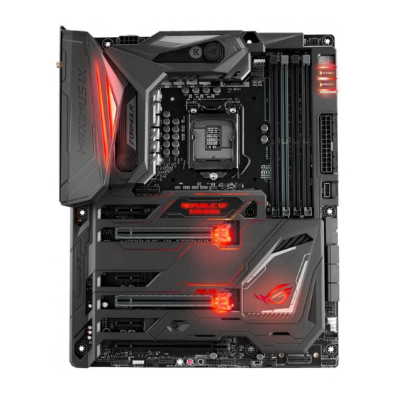
- Page 1 MAXIMUS FORMULA...
- Page 2 Product warranty or service will not be extended if: (1) the product is repaired, modified or altered, unless such repair, modification of alteration is authorized in writing by ASUS; or (2) the serial number of the product is defaced or missing.
-
Page 3: Table Of Contents
Contents Safety information ...................... vi About this guide ......................vii MAXIMUS IX FORMULA specifications summary ........... ix Package contents ...................... xv Installation tools and components ................. xvi Chapter 1: Product Introduction Motherboard overview ................1-1 1.1.1 Before you proceed ..............1-1 1.1.2... - Page 4 3.6.12 USB Configuration ..............3-19 Monitor menu ................... 3-20 Boot menu ....................3-20 Tool menu ....................3-22 3.9.1 ASUS EZ Flash 3 Utility ............3-22 3.9.2 Secure Erase ................3-22 3.9.3 ASUS Overclocking Profile ............3-24 3.9.4 ROG OC Panel H-Key Configure ..........3-24 3.9.5...
- Page 5 Rapid Storage Technology in UEFI BIOS ......4-2 ® 4.1.4 Intel Rapid Storage Technology Option ROM utility ....4-6 ® Creating a RAID driver disk ..............4-10 4.2.1 Creating a RAID driver disk in Windows ......... 4-10 ® Appendix Notices ........................A-1 ASUS contact information ..................A-6...
-
Page 6: Safety Information
Safety information Electrical safety • To prevent electrical shock hazard, disconnect the power cable from the electrical outlet before relocating the system. • When adding or removing devices to or from the system, ensure that the power cables for the devices are unplugged before the signal cables are connected. If possible, disconnect all power cables from the existing system before you add a device. -
Page 7: About This Guide
Refer to the following sources for additional information and for product and software updates. ASUS website The ASUS website (www.asus.com) provides updated information on ASUS hardware and software products. Optional documentation Your product package may include optional documentation, such as warranty flyers, that may have been added by your dealer. -
Page 8: Conventions Used In This Guide
Conventions used in this guide To ensure that you perform certain tasks properly, take note of the following symbols used throughout this manual. DANGER/WARNING: Information to prevent injury to yourself when trying to complete a task. CAUTION: Information to prevent damage to the components when trying to complete a task. -
Page 9: Maximus Ix Formula Specifications Summary
Processors. Before using Intel Optane memory modules, ® ® ensure that you have updated your motherboard drivers and BIOS to the latest version from ASUS support website. **** This function will work depending on the CPU installed. (continued on the next page) - Page 10 - 6 x USB 2.0 ports ( 4 ports at back panel [black], 2 ports at mid- board [black])* ASMedia USB 3.1 controller - supports ASUS USB 3.1 Boost: ® - 1 x USB 3.1 front panel connector - 2 x USB 3.1 ports (1 Type-A [red] and 1 Type-C [black] at back panel) * 2 x USB 2.0 ports at mid-board share with ROG extension (ROG_EXT)
- Page 11 MAXIMUS IX FORMULA specifications summary Extreme Engine Digi+ - MicroFine Alloy Choke - NexFET MOSFETs - 10K Black Metallic Capacitors Crosschill EK ROG Armor Pre-mounted I/O Shield ROG Aura - Aura effects (LOGO + ROG Armor RGB lighting) - 2 x Aura RGB strip headers...
- Page 12 MAXIMUS IX FORMULA specifications summary 1 x USB 3.1 front panel connector 1 x USB 3.0 header supports additional 2 USB 3.0 ports 1 x USB 2.0 header supports additional 2 USB 2.0 ports [ via ROG_EXT header] 6 x SATA 6Gb/s ports 1 x M.2 Socket 3 with M Key, type 2242/2260/2280/22110 storage...
- Page 13 MAXIMUS IX FORMULA specifications summary ASUS Dual Intelligent Processors 5 - 5-Way Optimization tuning key perfectly consolidates TPU, EPU, and Turbo App ASUS Exclusive Features - AI Suite 3 ASUS EZ DIY - USB BIOS Flashback - ASUS CrashFree BIOS 3...
- Page 14 7 32/64-bit are only supported when ® ® using 6th Generation Intel Processors ® ATX Form Factor, 12”x 9.6” (30.5cm x 24.4cm) Form Factor Specifications are subject to change without notice. Please refer to the ASUS website for the latest specifications.
-
Page 15: Package Contents
Package contents Check your motherboard package for the following items. Motherboard ROG MAXIMUS IX FORMULA 3 x 2-in-1 SATA 6 Gb/s cables Cables 1 x SLI HB bridge (2-WAY-M) ® 1 x 2T2R dual-band Wi-Fi moving antennas 1 x 10-in-1 ROG cable label... -
Page 16: Installation Tools And Components
Installation tools and components 1 Bag of screws Phillips (cross) screwdriver PC chassis Power supply unit Intel LGA 1151 CPU Intel LGA 1151 compatible CPU Fan ® ® DDR4 DIMM SATA hard disk drive SATA optical disc drive (optional) Graphics card (optional) The tools and components in the table above are not included in the motherboard package. -
Page 17: Chapter 1: Product Introduction
Chapter 1: Product Introduction Product Introduction Motherboard overview 1.1.1 Before you proceed Take note of the following precautions before you install motherboard components or change any motherboard settings. • Unplug the power cord from the wall socket before touching any component. • Before handling components, use a grounded wrist strap or touch a safely grounded object or a metal object, such as the power supply case, to avoid damaging them due to static electricity. • Hold components by the edges to avoid touching the ICs on them. • Whenever you uninstall any component, place it on a grounded antistatic pad or in the bag that came with the component. • Before you install or remove any component, ensure that the ATX power supply is switched off or the power cord is detached from the power supply. Failure to do so may cause severe damage to the motherboard, peripherals, or components. ASUS MAXIMUS IX FORMULA... -
Page 18: Motherboard Layout
1.1.2 Motherboard layout Refer to 1.1.9 Internal connectors and 2.3.1 Rear I/O connection for more information about rear panel connectors and internal connectors. Chapter 1: Product Introduction... -
Page 19: Layout Contents
14. Water in, water out, and water flow connectors (2-pin W_IN; 2-pin W_OUT; 1-31 3-pin W_FLOW) 15. System panel connectors (10-1 pin F_PANEL; 4-pin SPEAKER) 1-27 16. M.2 sockets (M.2_1; M.2_2) 1-30 17. Slow Mode switch (SLOW_MODE) 1-12 18. USB 2.0 connector (10-1 pin USB1314) 1-23 19. ROG Extension connector (18-1 pin ROG_EXT) 1-28 20. MemOK! button 1-10 21. Safe Boot button (SAFE_BOOT) 1-11 22. ReTry button (RETRY_BUTTON) 1-11 23. TPM connector (14-1 pin TPM) 1-31 24. Front panel audio connector (10-1 pin AAFP) 1-24 25. LED connectors (5-pin RGB_LED_STRIP1; RGB_LED_STRIP2) 1-24 ASUS MAXIMUS IX FORMULA... -
Page 20: Central Processing Unit (Cpu)
1.1.3 Central Processing Unit (CPU) This motherboard supports the New 7th Gen Intel Core™ processors on the LGA1151 ® package, with memory and PCI Express controllers integrated to support dual-channel (4 DIMM) DDR4 memory and 16 PCI Express 3.0/2.0 lanes. Ensure that you install the correct CPU designed for LGA1151 socket only. DO NOT install a CPU designed for LGA155 and LGA1156 sockets in the LGA1151 socket. • Ensure that all power cables are unplugged before installing the CPU. • Upon purchase of the motherboard, ensure that the PnP cap is on the socket and the socket contacts are not bent. Contact your retailer immediately if the PnP cap is missing, or if you see any damage to the PnP cap/socket contacts/motherboard components. ASUS will shoulder the cost of repair only if the damage is shipment/ transit-related. • Keep the cap after installing the motherboard. ASUS will process Return Merchandise Authorization (RMA) requests only if the motherboard comes with the cap on the LGA1151 socket. • The product warranty does not cover damage to the socket contacts resulting from incorrect CPU installation/removal, or misplacement/loss/incorrect removal of the PnP cap. Chapter 1: Product Introduction... -
Page 21: System Memory
1.1.4 System memory The motherboard comes with four Double Data Rate 4 (DDR4) Dual Inline Memory Modules (DIMM) slots. A DDR4 module is notched differently from a DDR, DDR2, or DDR3 module. DO NOT install a DDR, DDR2, or DDR3 memory module to the DDR4 slot. Recommended memory configurations ASUS MAXIMUS IX FORMULA... -
Page 22: Memory Configurations
Install a 64-bit Windows OS when you want to install 4GB or more on the motherboard. c) For more details, refer to the Microsoft ® support site at http://support.microsoft. com/kb/929605/en-us. • The design of the DIMM fan may vary. Ensure that the DIMM fan fits to the motherboard. • The default memory operation frequency is dependent on its Serial Presence Detect (SPD), which is the standard way of accessing information from a memory module. Under the default state, some memory modules for overclocking may operate at a lower frequency than the vendor-marked value. • For system stability, use a more efficient memory cooling system to support a full memory load (4 DIMMs) or overclocking condition. • Memory modules with memory frequency higher than 2133MHz and their corresponding timing or the loaded XMP profile is not the JEDEC memory standard. The stability and compatibility of the memory modules depend on the CPU’s capabilities and other installed devices. • Always install the DIMMS with the same CAS latency. For an optimum compatibility, we recommend that you install memory modules of the same version or data code (D/C) from the same vendor. Check with the vendor to get the correct memory modules. • ASUS exclusively provides hyper DIMM support function. • Hyper DIMM support is subject to the physical characteristics of individual CPUs. Load the X.M.P. or D.O.C.P. settings in the BIOS for the hyper DIMM support. • Visit the ASUS website for the latest QVL. Chapter 1: Product Introduction... -
Page 23: Expansion Slots
1.1.5 Expansion slots Unplug the power cord before adding or removing expansion cards. Failure to do so may cause you physical injury and damage motherboard components. Slot No. Slot Description PCIe 3.0 x1_1 slot PCIe 3.0 x16/x8_1 slot PCIe 3.0 x1_2 slot PCIe 3.0 x8_2 slot PCIe 3.0 x1_3 slot PCIe 3.0 x4_3 slot ASUS MAXIMUS IX FORMULA... -
Page 24: Irq Assignments For This Motherboard
IRQ assignments for this motherboard PCIEX16/X8_1 shared PCIEX8_2 shared PCIEX4_3 shared I.G.F.X. shared Intel LAN Controller shared SATA Controller shared High Definition Audio shared Intel XHCI Controller shared ASMedia 2142-1 shared ASMedia 2142-2 shared M.2_1 shared M.2_2 shared PCIe operating mode VGA Configuration PCIe_x16/x8_1 PCIe_x8_2 Single VGA/PCIe card x16 (Recommend for single VGA) Dual VGA/PCIe card • We recommend that you provide sufficient power when running CrossFireX™ or SLI ®... -
Page 25: Onboard Buttons And Switches
1.1.6 Onboard buttons and switches Onboard buttons and switches allow you to fine-tune performance when working on a bare or open-case system. This is ideal for overclockers and gamers who continually change settings to enhance system performance. Power-on button (START) The motherboard comes with a power-on button that allows you to power up or wake up the system. The LED near the button also lights up when the system is plugged to a power source indicating that you should shut down the system and unplug the power cable before removing or installing any motherboard component. RESET button (RESET) Press the reset button to reboot the system. ASUS MAXIMUS IX FORMULA... - Page 26 • Refer to section 1.1.7 Onboard LEDs for the exact location of the DRAM_LED. • The DRAM_LED also lights up when the DIMM is not properly installed. Turn off the system and reinstall the DIMM before using the MemOK! function. • The MemOK! button does not function under Windows OS environment. ® • During the tuning process, the system loads and tests failsafe memory settings. It takes about 30 seconds for the system to test one set of failsafe settings. If the test fails, the system reboots and test the next set of failsafe settings. The blinking speed of the DRAM_LED increases, indicating different test processes. • Due to memory tuning requirement, the system automatically reboots when each timing set is tested. If the installed DIMMs still fail to boot after the whole tuning process, the DRAM_LED lights continuously. Replace the DIMMs with ones recommended in the Memory QVL (Qualified Vendors Lists) in this user manual or at www.asus.com. • If you turn off the computer and replace DIMMs during the tuning process, the system continues memory tuning after turning on the computer. To stop memory tuning, turn off the computer and unplug the power cord for about 5–10 seconds. • If your system fails to boot up due to BIOS overclocking, press the MemOK! button to boot and load the BIOS default settings. A message will appear during POST reminding you that the BIOS has been restored to its default settings. • We recommend that you download and update to the latest BIOS version from www.asus.com after using the MemOK! function. Chapter 1: Product Introduction 1-10...
- Page 27 Safe Boot button (SAFE_BOOT) The Safe Boot button can be pressed anytime to force the system to reboot into the BIOS safe mode. This button temporarily applies safe settings to the BIOS while retaining any overclocked settings allowing you to modify the settings causing boot failure. Use this button when overclocking or tweaking the settings of your system. ReTry button (RETRY_BUTTON) The ReTry button is specially designed for overclockers and is most useful during the booting process where the Reset button is rendered useless. When pressed, it forces the system to reboot while retaining the same settings to be retried in quick succession to achieve a successful POST. ASUS MAXIMUS IX FORMULA 1-11...
- Page 28 Slow Mode Switch (SLOW_MODE) Slow Mode Switch is employed during LN2 benching. The system may crash due to the CPU being unstable when using extreme overclocking, enabling slow mode will decrease the processor frequency and stabilize the system, allowing overclockers to keep track of their overclocking data. Chapter 1: Product Introduction 1-12...
-
Page 29: Onboard Leds
1.1.7 Onboard LEDs Q LEDs (BOOT_DEVICE_LED, VGA_LED, DRAM_LED, CPU_LED) Q LEDs check key components (CPU, DRAM, VGA card, and booting devices) in sequence during motherboard booting process. If an error is found, the corresponding LED remains lit until the problem is solved. This user-friendly design provides an intuitive way to locate the root problem within seconds. Button LEDs (BTN_LED1-2) These LEDs are designed to indicate the location of the START and RESET buttons. ASUS MAXIMUS IX FORMULA 1-13... - Page 30 Q-Code LED The Q-Code LED design provides you with a 2-digit error code that displays the system status. Refer to the Q-Code table on the following page for details. Chapter 1: Product Introduction 1-14...
- Page 31 Pre-memory PCH initialization is started 19 – 1C 2B – 2F Memory initialization Reserved for ASL (see ASL Status Codes section below) Memory Installed 32 – 36 CPU post-memory initialization 37 – 3A Post-Memory System Agent initialization is started 3B – 3E Post-Memory PCH initialization is started DXE IPL is started Memory initialization error. Invalid memory type or incompatible memory 50 – 53 speed Unspecified memory initialization error Memory not installed Invalid CPU type or Speed CPU mismatch CPU self test failed or possible CPU cache error CPU micro-code is not found or micro-code update is failed (continued on the next page) ASUS MAXIMUS IX FORMULA 1-15...
- Page 32 Q-Code table Code Description Internal CPU error Reset PPI is not available Reserved for future AMI error codes 5C – 5F S3 Resume is stared (S3 Resume PPI is called by the DXE IPL) S3 Boot Script execution Video repost OS S3 wake vector call Reserved for future AMI progress codes E4 – E7 S3 Resume Failed S3 Resume PPI not Found S3 Resume Boot Script Error S3 OS Wake Error Reserved for future AMI error codes EC – EF Recovery condition triggered by firmware (Auto recovery) Recovery condition triggered by user (Forced recovery) Recovery process started Recovery firmware image is found Recovery firmware image is loaded Reserved for future AMI progress codes F5 – F7 Recovery PPI is not available Recovery capsule is not found Invalid recovery capsule Reserved for future AMI error codes FB – FF DXE Core is started NVRAM initialization Installation of the PCH Runtime Services...
- Page 33 73 – 77 ACPI module initialization CSM initialization Reserved for future AMI DXE codes 7A – 7F Boot Device Selection (BDS) phase is started Driver connecting is started PCI Bus initialization is started PCI Bus Hot Plug Controller Initialization PCI Bus Enumeration PCI Bus Request Resources PCI Bus Assign Resources Console Output devices connect Console input devices connect Super IO Initialization USB initialization is started USB Reset USB Detect USB Enable Reserved for future AMI codes 9E – 9F IDE initialization is started IDE Reset IDE Detect IDE Enable SCSI initialization is started SCSI Reset SCSI Detect SCSI Enable Setup Verifying Password (continued on the next page) ASUS MAXIMUS IX FORMULA 1-17...
- Page 34 Q-Code table Code Description Start of Setup Reserved for ASL (see ASL Status Codes section below) Setup Input Wait Reserved for ASL (see ASL Status Codes section below) Ready To Boot event Legacy Boot event Exit Boot Services event Runtime Set Virtual Address MAP Begin Runtime Set Virtual Address MAP End Legacy Option ROM Initialization System Reset USB hot plug Clean-up of NVRAM Configuration Reset (reset of NVRAM settings) Reserved for future AMI codes B8– BF CPU initialization error System Agent initialization error PCH initialization error Some of the Architectural Protocols are not available PCI resource allocation error. Out of Resources No Space for Legacy Option ROM No Console Output Devices are found No Console Input Devices are found Invalid password Error loading Boot Option (LoadImage returned error) Boot Option is failed (StartImage returned error) Flash update is failed Reset protocol is not available PCI bus hot plug Chapter 1: Product Introduction 1-18...
- Page 35 ACPI/ASL Checkpoints Code Description 0x01 System is entering S1 sleep state 0x02 System is entering S2 sleep state System is entering S3 sleep state 0x03 System is entering S4 sleep state 0x04 System is entering S5 sleep state 0x05 System is waking up from the S1 sleep state 0x10 System is waking up from the S2 sleep state 0x20 System is waking up from the S3 sleep state 0x30 System is waking up from the S4 sleep state 0x40 0xAC System has transitioned into ACPI mode. Interrupt controller is in PIC mode. 0xAA System has transitioned into ACPI mode. Interrupt controller is in APIC mode. ASUS MAXIMUS IX FORMULA 1-19...
-
Page 36: Jumper
1.1.8 Jumper LN2 Mode jumper (3-pin LN2_MODE) With LN2 mode activated, the ROG motherboard is optimized to remedy the cold-boot bug during POST and help the system boot successfully. Chapter 1: Product Introduction 1-20... -
Page 37: Internal Connectors
Z270 Serial ATA 6 Gb/s connectors (7-pin SATA6G_12; SATA6G_34; ® SATA6G_56) These connectors connect to Serial ATA 6 Gb/s hard disk drives via Serial ATA 6 Gb/s signal cables. If you installed Serial ATA hard disk drives, you can create a RAID 0, 1, 5, and 10 configuration with the Intel Rapid Storage Technology through the onboard Intel ® ® Z270 chipset. • These connectors are set to [AHCI] by default. If you intend to create a Serial ATA RAID set using these connectors, set the SATA Mode Selection item in the BIOS to [Intel RST Premium With Intel Optane System Acceleration (RAID)]. • Before creating a RAID set, refer to section RAID configurations or the manual bundled in the motherboard support DVD. • When using NCQ, set the SATA Mode in the BIOS to [AHCI]. ASUS MAXIMUS IX FORMULA 1-21... - Page 38 USB 3.1 front panel connector (USB3.1_E1) This connector allows you to connect a USB 3.1 module for additional USB 3.1 ports. The latest USB 3.1 connectivity provides data transfer speeds of up to 10 Gbps. The next-generation standard is completely backward-compatible with your existing USB devices. USB 3.0 connector (20-1 pin USB3_12) This connector allows you to connect a USB 3.0 module for additional USB 3.0 front or rear panel ports. With an installed USB 3.0 module, you can enjoy all the benefits of USB 3.0 including faster data transfer speeds of up to 5 Gbps, faster charging time for USB-chargeable devices, optimized power efficiency, and backward compatibility with USB 2.0. The USB 3.0 module is purchased separately. Chapter 1: Product Introduction 1-22...
- Page 39 USB 2.0 connector (10-1 pin USB1314) This connector is for USB 2.0 port. Connect the USB module cable to this connector, then install the module to a slot opening at the back of the system chassis. This USB connector complies with USB 2.0 specification that supports up to 480 MBps connection speed. Never connect a 1394 cable to the USB connectors. Doing so will damage the motherboard! 1 x USB 2.0 port (USB1314) at mid-board shares pins with ROG extension (ROG_EXT) port. ASUS MAXIMUS IX FORMULA 1-23...
- Page 40 Front panel audio connector (10-1 pin AAFP) This connector is for a chassis-mounted front panel audio I/O module that supports HD Audio standard. Connect one end of the front panel audio I/O module cable to this connector. We recommend that you connect a high-definition front panel audio module to this connector to avail of the motherboard’s high-definition audio capability. LED connectors (5-pin RGB_LED_STRIP1; RGB_LED_STRIP2) These LED connectors are for connecting LED strips on your cover and PCH. Chapter 1: Product Introduction 1-24...
- Page 41 • Ensure to fully insert the 4-pin CPU fan cable to the CPU fan connector. • For better Q-Fan functions, we recommend using 4-pin PWM fans when you connect powerful fans (1A or above) onto the H_AMP_FAN connector. • Ensure to disable Q-Fan functions if you want to connect powerful 3-pin DC fans (1A or above) onto the H_AMP_FAN connector. • W_PUMP+ function support depends on water cooling device. Header Max. Current Max. Power Default Speed Shared Control CPU_FAN Q-Fan Controlled CPU_OPT Q-Fan Controlled CHA_FAN1 Q-Fan Controlled CHA_FAN2 Q-Fan Controlled CHA_FAN3 Q-Fan Controlled AIO_PUMP Full Speed W_PUMP+ Full Speed H_AMP Q-Fan Controlled ASUS MAXIMUS IX FORMULA 1-25...
- Page 42 ATX power connectors (24-pin EATXPWR; 8-pin EATX12V) These connectors are for ATX power supply plugs. The power supply plugs are designed to fit these connectors in only one orientation. Find the proper orientation and push down firmly until the connectors completely fit. • For a fully configured system, we recommend that you use a power supply unit (PSU) that complies with ATX 12 V Specification 2.0 (or later version) and provides a minimum power of 350 W. • Do not forget to connect the 8-pin EATX12 V power plug. Otherwise, the system will not boot. • We recommend that you use a PSU with a higher power output when configuring a system with more power-consuming devices. The system may become unstable or may not boot up if the power is inadequate. • If you want to use two or more high-end PCIe x16 cards, use a PSU with 1000W power or above to ensure the system stability. Chapter 1: Product Introduction 1-26...
-
Page 43: System Panel Connector
System panel connectors (10-1 pin F_PANEL; 4-pin SPEAKER) These connectors supports several chassis-mounted functions. • System power LED (2-pin PLED) This 2-pin connector is for the system power LED. Connect the chassis power LED cable to this connector. The system power LED lights up when you turn on the system power, and blinks when the system is in sleep mode. • Hard disk drive activity LED (2-pin HDD_LED) This 2-pin connector is for the HDD Activity LED. Connect the HDD Activity LED cable to this connector. The HDD LED lights up or flashes when data is read from or written to the HDD. • System warning speaker (4-pin SPEAKER) This 4-pin connector is for the chassis-mounted system warning speaker. The speaker allows you to hear system beeps and warnings. • ATX power button/soft-off button (2-pin PWRBTN) This connector is for the system power button. Pressing the power button turns the system on or puts the system in sleep or soft-off mode depending on the BIOS settings. Pressing the power button for more than four seconds while the system is ON turns the system OFF. • Reset button (2-pin RESET) This 2-pin connector is for the chassis-mounted reset button for system reboot without turning off the system power. ASUS MAXIMUS IX FORMULA 1-27... - Page 44 ROG extension connector (18-1 pin ROG_EXT) This connector is for the OC Panel I/II. • The OC Panel I/II and Front Base are purchased separately. • Support for OC Panel I/II and Front Base varies over different platforms • Visit www.asus.com for more information about the devices and the latest compatibility list. Thermal sensor connector (2-pin T_SENSOR) This connector is for the thermistor cable that allows you to monitor the temperature of your motherboard’s critical components and connected devices. Chapter 1: Product Introduction 1-28...
- Page 45 AURA RGB headers (4-pin RGB_HEADER1-2) These connectors are for RGB LED strips. The RGB header supports 5050 RGB multi-color LED strips (12V/G/R/B), with a maximum power rating of 2A (12V), and no longer than 2 m. Before you install or remove any component, ensure that the ATX power supply is switched off or the power cord is detached from the power supply. Failure to do so may cause severe damage to the motherboard, peripherals, or components. • Actual lighting and color will vary with LED strips. • If your LED strip does not light up, check if the RGB LED extension cable and the RGB LED strip is connected in the correct orientation, and the 12V connector is aligned with the 12V header on the motherboard. • The LED strip will only light up when the system is operating. • The LED strips are purchased separately. ASUS MAXIMUS IX FORMULA 1-29...
- Page 46 M.2 sockets (M.2_1; M.2_2) These sockets allow you to install M.2 SSD modules. • M.2_1 socket supports PCIe 3.0 x4 and SATA mode M Key design and type 2242 / 2260 / 2280 / 22110 PCIe and SATA storage devices. • M.2_2 socket supports PCIe 3.0 x4 M Key design and type 2242 / 2260 / 2280 PCIe storage devices. • These sockets support IRST (Intel Rapid Storage Technology). ® • When the M.2_1(Socket 3) is operating in SATA mode, SATA port 1 (SATA6G_1) will be disabled. • The M.2 SSD module is purchased separately. Chapter 1: Product Introduction 1-30...
- Page 47 TPM connector (14-1 pin TPM) This connector supports a Trusted Platform Module (TPM) system, which securely stores keys, digital certificates, passwords and data. A TPM system also helps enhance network security, protect digital identities, and ensures platform integrity. The TPM module is purchased separately. Water in, water out, and water flow connectors (2-pin W_IN; 2-pin W_OUT; 3-pin W_FLOW) These connectors allow you to connect sensors to monitor the temperature and flow rate of your liquid cooling system. You can manually adjust the fans and water pump to optimize the thermal efficiency of your liquid cooling system. ASUS MAXIMUS IX FORMULA 1-31...
- Page 48 Chapter 1: Product Introduction 1-32...
-
Page 49: Chapter 2: Basic Installation
The diagrams in this section are for reference only. The motherboard layout may vary with models, but the installation steps are the same for all models. Place the motherboard into the chassis, ensuring that its rear I/O ports are aligned to the chassis’ rear I/O panel. ASUS MAXIMUS IX FORMULA... - Page 50 Place nine (9) screws into the holes indicated by circles to secure the motherboard to the chassis. DO NOT over tighten the screws! Doing so can damage the motherboard. Chapter 2: Basic Installation...
-
Page 51: Cpu Installation
Ensure that you install the correct CPU designed for LGA1151 socket only. DO NOT install a CPU designed for LGA1155 and LGA1156 sockets on the LGA1151 socket. Top of CPU Bottom of CPU Bottom of CPU ASUS MAXIMUS IX FORMULA... - Page 52 Top of CPU • The CPU Installation Tool is only compatible on ASUS motherboards with a Intel ® LGA1151 socket. • Ensure that the CPU is firmly clicked into place before installing it onto the CPU socket on the motherboard. • Use the CPU Installation Tool for installing the CPU only. DO NOT damage or bend the CPU Installation Tool. • Always firmly hold both sides of the CPU Installation Tool when installing, removing, or picking up the CPU Installation Tool. • Ensure to use a soft stable surface when installing the CPU to the CPU Installation Tool to prevent CPU damage. • ASUS will not cover damages resulting from incorrect CPU installation/removal, incorrect CPU orientation/placement, or other damages resulting from negligence by the user.
-
Page 53: Cpu Heatsink And Fan Assembly Installation
2.1.3 CPU heatsink and fan assembly installation Apply the Thermal Interface Material to the CPU heatsink and CPU before you install the heatsink and fan, if necessary. To install the CPU heatsink and fan assembly ASUS MAXIMUS IX FORMULA... - Page 54 To uninstall the CPU heatsink and fan assembly Chapter 2: Basic Installation...
-
Page 55: Dimm Installation
2.1.4 DIMM installation To remove a DIMM ASUS MAXIMUS IX FORMULA... -
Page 56: Atx Power Connection
2.1.5 ATX power connection Ensure to connect the 8-pin power plug. 2.1.6 SATA device connection Chapter 2: Basic Installation... -
Page 57: Front I/O Connector
This connector will only fit in one orientation. Push the connector until it clicks into place. To install USB 3.0 connector To install USB 2.0 connector USB 3.0 USB 2.0 To install front panel audio connector To install system speaker connector AAFP ASUS MAXIMUS IX FORMULA... -
Page 58: Expansion Card Installation
2.1.8 Expansion card installation To install PCIe x16 cards To install PCIe x1 cards Chapter 2: Basic Installation 2-10... -
Page 59: M.2 Installation
2.1.9 M.2 installation ASUS MAXIMUS IX FORMULA 2-11... -
Page 60: Wi-Fi Antenna Installation
2.1.10 Wi-Fi antenna installation Installing the ASUS 2T2R dual band W-Fi antenna Connect the bundled ASUS 2T2R dual band Wi-Fi antenna connector to the Wi-Fi ports at the back of the chassis. IO Shield • Ensure that the ASUS 2T2R dual band Wi-Fi antenna is securely installed to the Wi-Fi ports. • Ensure to install the Bluetooth driver before installing the Wi-Fi GO! software. • Ensure that the antenna is at least 20 cm away from all persons. The illustration above is for reference only. The I/O port layout may vary with models, but the Wi-Fi antenna installation procedure is the same for all models. -
Page 61: Bios Update Utility
BIOS or operating system. Simply insert a USB storage device to the USB port, press the USB BIOS Flashback button for three seconds, and the BIOS is updated automatically. To use USB BIOS Flashback: 1. Download the latest BIOS file from the ASUS website. Extract and rename the BIOS image file to M9F.CAP. Copy M9F.CAP to the root directory of your USB storage device. Turn off the system and connect the USB storage device to the USB BIOS Flashback port. Press the USB BIOS Flashback button. A flashing light indicates that the BIOS Flashback function is enabled. The light goes out when the process of updating the BIOS is complete. USB BIOS Flashback button USB BIOS Flashback port • For more BIOS update utilities in BIOS setup, refer to the section Updating BIOS in Chapter 3. • Connect your USB keyboard on the KeyBot port if you want to use the KeyBot feature. Updating BIOS may have risks. If the BIOS program is damaged during the process and results to the system’s failure to boot up, please contact your local ASUS Service Center. ASUS MAXIMUS IX FORMULA 2-13... -
Page 62: Motherboard Rear And Audio Connections
Motherboard rear and audio connections 2.3.1 Rear I/O connection Rear panel connectors Clear CMOS button (CLR_CMOS). Press this button to clear the BIOS setup information only when the systems hangs due to overclocking. DisplayPort Intel USB 2.0 ports 7, 8, 9, and 10 ® Intel USB 3.0 ports 3, 4, 5, and 6 ® LAN (RJ-45) port* USB BIOS Flashback button Wi-Fi 802.11 a/b/g/n/ac, Bluetooth V4.1 HDMI port USB 3.1 Type-A port EA3 USB 3.1 Type-C port EC2 Optical S/PDIF OUT port Audio I/O ports** * and ** : Refer to the tables on the next page for LAN port LEDs, and audio port definitions. Chapter 2: Basic Installation 2-14... -
Page 63: Audio I/O Connections
Side Speaker Out Lime Line Out Front Speaker Out Front Speaker Out Front Speaker Out Pink Mic In Mic In Mic In Mic In Orange – – Center/Sub Center/Sub woofer woofer Black – Rear Speaker Out Rear Speaker Out Rear Speaker Out 2.3.2 Audio I/O connections Audio I/O ports ASUS MAXIMUS IX FORMULA 2-15... - Page 64 Connect to Headphone and Mic Connect to Stereo Speakers Connect to 2 channel Speakers Chapter 2: Basic Installation 2-16...
- Page 65 Connect to 4 channel Speakers Connect to 6 channel Speakers Connect to 8 channel Speakers ASUS MAXIMUS IX FORMULA 2-17...
-
Page 66: Starting Up For The First Time
Starting up for the first time After making all the connections, replace the system case cover. Ensure that all switches are off. Connect the power cord to the power connector at the back of the system chassis. Connect the power cord to a power outlet that is equipped with a surge protector. Turn on the devices in the following order: Monitor b. External SCSI devices (starting with the last device on the chain) -
Page 67: Chapter 3: Bios Setup
BIOS Setup Knowing BIOS The new ASUS UEFI BIOS is a Unified Extensible Interface that complies with UEFI architecture, offering a user-friendly interface that goes beyond the traditional keyboard- only BIOS controls to enable a more flexible and convenient mouse input. You can easily navigate the new UEFI BIOS with the same smoothness as your operating system. -
Page 68: Bios Setup Program
RTC RAM via the Clear CMOS button. • The BIOS setup program does not support the Bluetooth devices. Please visit ASUS website for the detailed BIOS content manual. BIOS menu screen The BIOS Setup program can be used under two modes: EZ Mode and Advanced Mode. -
Page 69: Ez Mode
Click to go to Advanced mode Loads optimized Search on the FAQ default settings Click to display boot devices Selects the boot device priority The boot device options vary depending on the devices you installed to the system. ASUS MAXIMUS IX FORMULA... -
Page 70: Advanced Mode
3.2.2 Advanced Mode The Advanced Mode provides advanced options for experienced end-users to configure the BIOS settings. The figure below shows an example of the Advanced Mode. Refer to the following sections for the detailed configurations. To switch from EZ Mode to Advanced Mode, click Advanced Mode(F7) or press the <F7> hotkey. -
Page 71: Menu Bar
This button above the menu bar allows you to view and tweak the overclocking settings of your system. It also allows you to change the motherboard’s SATA mode from AHCI to RAID mode. Refer to section 3.2.4 EZ Tuning Wizard for more information. ASUS MAXIMUS IX FORMULA... -
Page 72: Hot Keys
Move your mouse over this button to show a QR code, scan this QR code on your mobile device to connect to the BIOS FAQ web page of the ASUS support website. You can also scan the following QR code: Hot keys This button above the menu bar contains the navigation keys for the BIOS setup program. -
Page 73: Qfan Control
Click to activate DC Mode configured PWM Mode Select a profile to Click to apply the fan setting apply to your fans Click to undo the Click to go back to main menu changes Select to manually configure your fans ASUS MAXIMUS IX FORMULA... - Page 74 Configuring fans manually Select Manual from the list of profiles to manually configure your fans’ operating speed. Speed points Select to manually configure your fans To configure your fans: Select the fan that you want to configure and to view its current status. Click and drag the speed points to adjust the fans’...
-
Page 75: Ez Tuning Wizard
To start OC Tuning: Press <F11> on your keyboard or click from the BIOS screen to open EZ Tuning Wizard screen. Click OC then click Next. Select a PC scenario Daily Computing or Gaming/Media Editing, then click Next. ASUS MAXIMUS IX FORMULA... -
Page 76: Creating Raid
Select a Main Cooling System BOX cooler, Tower cooler, Water cooler, or I’m not sure, then click Next. After selecting the Main Cooling System, click Next then click Yes to start the OC Tuning. Creating RAID To create RAID: Press <F11> on your keyboard or click from the BIOS screen to open EZ Tuning Wizard screen. - Page 77 After selecting the type of RAID, click Next then click Yes to continue the RAID setup. After the RAID setup is done, click Yes to exit the setup then click OK to reset your system. ASUS MAXIMUS IX FORMULA 3-11...
-
Page 78: My Favorites
My Favorites My Favorites is your personal space where you can easily save and access your favorite BIOS items. My Favorites comes with several performance, power saving, and fast boot related items by default. You can personalize this screen by adding or removing items. Chapter 3: BIOS Setup 3-12... - Page 79 Configuration items such as Memory SPD Information, system time and date. Click Exit (ESC) or press <Esc> key to close Setup Tree Map screen. Go to My Favorites menu to view the saved BIOS items. ASUS MAXIMUS IX FORMULA 3-13...
-
Page 80: Main Menu
Main menu The Main menu screen appears when you enter the Advanced Mode of the BIOS Setup program. The Main menu provides you an overview of the basic system information, and allows you to set the system date, time, language, and security settings. Security The Security menu items allow you to change the system security settings. -
Page 81: Dram Frequency
CPU permanently. ASUS MultiCore Enhancement [Auto] This item allows you to maximize the oveclocking performance optimized by ASUS core ratio settings. [Disabled] This item allows you to set to default core ratio settings. CPU Core Ratio This item allows you to set the CPU core ratios. -
Page 82: Advanced Menu
Internal CPU Power Management The subitems in this menu allow you to set the CPU ratio and features. Intel(R) SpeedStep(tm) Allows the operating system to dynamically adjust the processor voltage and cores frequency to decrease the average power consumption and decrease average heat production. -
Page 83: Platform Misc Configuration
SMART Self Test SMART (Self-Monitoring, Analysis and Reporting Technology) is a monitoring system that shows a warning message during POST (Power-on Self Test) when an error occurs in the hard disks. Configuration options: [On] [Off] ASUS MAXIMUS IX FORMULA 3-17... -
Page 84: Pch-Fw Configuration
SATA6G_1(Gray) - SATA6G_6(Gray) SATA6G_1(Gray) - SATA6G_6(Gray) This item allows you to enable or disable the selected SATA port. Configuration options: [Disabled] [Enabled] Hot Plug These items appears only when the SATA Mode Selection is set to [AHCI] and allows you to enable or disable SATA Hot Plug Support. Configuration options: [Disabled] [Enabled] 3.6.6 PCH-FW Configuration... -
Page 85: Apm Configuration
The Mass Storage Devices item shows the auto-detected values. If no USB device is detected, the item shows None. USB Single Port Control This item allows you to enable or disable the individual USB ports. Refer to section 1.1.2 Motherboard layout for the location of the USB ports. ASUS MAXIMUS IX FORMULA 3-19... -
Page 86: Monitor Menu
Monitor menu The Monitor menu displays the system temperature/power status, and allows you to change the fan settings. Qfan Configuration Qfan Tuning Click this item to automatically detect the lowest speed and configure the minimum duty cycle for each fan. AIO PUMP/W_PUMP+ Control [Disabled] Disable the Water Pump control feature. -
Page 87: Secure Boot
Configuration options: [Legacy only] [UEFI driver first] Secure Boot This item allows you to configure the Windows Secure Boot settings and manage its keys to ® protect the system from unauthorized access and malwares during POST. ASUS MAXIMUS IX FORMULA 3-21... -
Page 88: Tool Menu
3.9.1 ASUS EZ Flash 3 Utility This item allows you to run ASUS EZ Flash 3. When you press <Enter>, a confirmation message appears. Use the left/right arrow key to select between [Yes] or [No], then press <Enter> to confirm your choice. - Page 89 Check the ASUS support site for a full list of SSDs tested with Secure Erase. The drive may become unstable if you run Secure Erase on an incompatible SSD. • The time to erase the contents of your SSD may take a while depending on its size.
-
Page 90: Asus Overclocking Profile
3.9.3 ASUS Overclocking Profile This item allows you to store or load multiple BIOS settings. Load Profile This item allows you to load the previous BIOS settings saved in the BIOS Flash. Key in the profile number that saved your BIOS settings, press <Enter>, and then select Yes. -
Page 91: Graphics Card Information
This item displays the information and recommended configuration for the PCIE slots that the graphics card is installed in your system. This feature is only supported on selected ASUS graphics cards. Bus Interface This item allows you to select the bus interface. -
Page 92: Updating Bios
® ASUS EZ Flash 3: Updates the BIOS using a USB flash drive. ASUS CrashFree BIOS 3: Restores the BIOS using the motherboard support DVD or a USB flash drive when the BIOS file fails or gets corrupted. 3.11.1... -
Page 93: Asus Ez Flash 3
3.11.2 ASUS EZ Flash 3 ASUS EZ Flash 3 allows you to download and update to the latest BIOS through the Internet without having to use a bootable floppy disk or an OS-based utility. Updating through the Internet varies per region and Internet conditions. Check your local Internet connection before updating through the Internet. - Page 94 To update the BIOS by Internet: Enter the Advanced Mode of the BIOS setup program. Go to the Tool menu to select ASUS EZ Flash Utility and press <Enter>. Select by Internet. Press the Left/Right arrow keys to select an Internet connection method, and then press <Enter>.
-
Page 95: Asus Crashfree Bios 3
The BIOS file in the motherboard support DVD may be older than the BIOS file published on the ASUS official website. If you want to use the newer BIOS file, download the file at https://www.asus.com/support/ and save it to a USB flash drive. - Page 96 Chapter 3: BIOS Setup 3-30...
-
Page 97: Chapter 4: Raid Support
With the RAID 10 configuration you get all the benefits of both RAID 0 and RAID 1 configurations. Use four new hard disk drives or use an existing drive and three new drives for this setup. ASUS MAXIMUS IX FORMULA... -
Page 98: Installing Serial Ata Hard Disks
4.1.2 Installing Serial ATA hard disks The motherboard supports Serial ATA hard disk drives. For optimal performance, install identical drives of the same model and capacity when creating a disk array. To install the SATA hard disks for a RAID configuration: Install the SATA hard disks into the drive bays. - Page 99 When the RAID Level item is selected, press <Enter> to select the RAID level to create, and then press <Enter>. Under Select Disks, press <Enter> and select X for the disks you want to include in the RAID set. ASUS MAXIMUS IX FORMULA...
- Page 100 When the Strip Size item is selected, press <Enter> to select strip size for the RAID array (for RAID 0, 10 and 5 only), and then press <Enter>. The available strip size values range from 4 KB to 128 KB. The following are typical values: RAID 0: 128 KB RAID 10: 64 KB RAID 5: 64 KB...
- Page 101 <Enter>. The following screen appears: When the Delete item is selected, press <Enter>, then select Yes to delete the RAID volume and return to the Intel Rapid Storage Technology menu, or select No to ® cancel. ASUS MAXIMUS IX FORMULA...
-
Page 102: Intel ® Rapid Storage Technology Option Rom Utility
4.1.4 Intel Rapid Storage Technology Option ROM utility ® To enter the Intel Rapid Storage Technology Option ROM utility: ® Turn on the system. During POST, press <Ctrl> + <I> to display the utility main menu. RAID Volumes: None defined. Physical Devices: Port Device Model... - Page 103 Serial # Size Status ST3160812AS 9LS0HJA4 149.0GB Non-RAID Disk ST3160812AS 9LS0F4HL 149.0GB Non-RAID Disk ST3160812AS 3LS0JYL8 149.0GB Non-RAID Disk ST3160812AS 9LS0BJ5H 149.0GB Non-RAID Disk Select 2 to 6 to use in creating the volume. [↑↓]-Prev/Next [SPACE]-SelectDisk [ENTER]-Done ASUS MAXIMUS IX FORMULA...
- Page 104 Use the up/down arrow key to select a drive, and then press <Space> to select. A small triangle marks the selected drive. Press <Enter> after completing your selection. Use the up/down arrow key to select the strip size for the RAID array (for RAID 0, 10 and 5 only),and then press <Enter>.
- Page 105 (This does not apply to Recovery volumes) Are you sure you want to delete “Volume0”? (Y/N): Press <Y> to delete the RAID set and return to the utility main menu, or press <N> to return to the DELETE VOLUME menu. ASUS MAXIMUS IX FORMULA...
-
Page 106: Creating A Raid Driver Disk
Exiting the Intel Rapid Storage Technology Option ROM utility ® To exit the utility: From the utility main menu, select 5. Exit, and then press <Enter>. The following warning message appears: [CONFIRM EXIT] Are you sure you want to exit? (Y/N): Press <Y>... -
Page 107: Appendix
Consult the dealer or an experienced radio/TV technician for help. The use of shielded cables for connection of the monitor to the graphics card is required to assure compliance with FCC regulations. Changes or modifications to this unit not expressly approved by the party responsible for compliance could void the user’s authority to operate this equipment. ASUS MAXIMUS IX FORMULA... -
Page 108: Canadian Department Of Communications Statement
IC: Canadian Compliance Statement Complies with the Canadian ICES-003 Class B specifications. This device complies with RSS 210 of Industry Canada. This Class B device meets all the requirements of the Canadian interference-causing equipment regulations. This device complies with Industry Canada license exempt RSS standard(s). Operation is subject to the following two conditions: (1) this device may not cause interference, and (2) this device must accept any interference, including interference that may cause undesired operation of the device. -
Page 109: Rf Equipment Notices
ASUS Recycling/Takeback Services ASUS recycling and takeback programs come from our commitment to the highest standards for protecting our environment. We believe in providing solutions for you to be able to responsibly recycle our products, batteries, other components as well as the packaging materials. - Page 110 FCC Bluetooth Wireless Compliance The antenna used with this transmitter must not be co-located or operated in conjunction with any other antenna or transmitter subject to the conditions of the FCC Grant. Bluetooth Industry Canada Statement This Class B device meets all requirements of the Canadian interference-causing equipment regulations. Cet appareil numérique de la Class B respecte toutes les exigences du Règlement sur le matériel brouilleur du Canada.
- Page 111 1999/5/ EZ. Cijeli tekst EU izjave o sukladnosti dostupan je na: www.asus.com/support Toto zariadenie môže byť prevádzkované v dolu uvedených krajinách: Ovaj uređaj može se koristiti u dolje navedenim zemljama: Slovenščina ASUSTeK Computer Inc.
-
Page 112: Asus Contact Information
800 Corporate Way, Fremont, CA 94539, USA Telephone +1-510-739-3777 +1-510-608-4555 Web site http://www.asus.com/us/ Technical Support Support fax +1-812-284-0883 Telephone +1-812-282-2787 Online support http://qr.asus.com/techserv ASUS COMPUTER GmbH (Germany and Austria) Address Harkort Str. 21-23, 40880 Ratingen, Germany +49-2102-959931 Web site http://www.asus.com/de Online contact http://eu-rma.asus.com/sales Technical Support Telephone +49-2102-5789555 Support Fax +49-2102-959911 Online support http://qr.asus.com/techserv... -
Page 113: Declaration Of Conformity
800 Corporate Way, Fremont Phone/Fax No: (510)739-3777/(510)608-4555 hereby declares that the product Product Name : Motherboard Model Number : MAXIMUS IX FORMULA Conforms to the following specifications: FCC Part 15, Subpart B, Unintentional Radiators Supplementary Information: This device complies with part 15 of the FCC Rules. Operation is subject to the... - Page 114 Appendix...
Need help?
Do you have a question about the MAXIMUS IX FORMULA and is the answer not in the manual?
Questions and answers