Table of Contents
Advertisement
Save This Manual for Future Reference
Two-Stage Snow Blower
Operator's Manual
MODEL NUMBER
YB5765
SERIAL NUMBER
PURCHASE DATE
Both model number and serial
number may be found on the
main label. You should record
both of them in a safe place for
future use.
FOR YOUR SAFETY
READ AND UNDERSTAND THE ENTIRE MANUAL BEFORE OPERATING MACHINE
Tame the Great Outdoors
TM
Advertisement
Table of Contents

Subscribe to Our Youtube Channel
Related Manuals for YARDMAX YB5765


Summary of Contents for YARDMAX YB5765
-
Page 1: For Your Safety
Save This Manual for Future Reference Two-Stage Snow Blower Operator’s Manual MODEL NUMBER YB5765 SERIAL NUMBER PURCHASE DATE Both model number and serial number may be found on the main label. You should record both of them in a safe place for future use. -
Page 2: Table Of Contents
Up for the job? YARDMAX is. When looking for outdoor power equipment (OPE) to get the job done right, at the right price, YARDMAX delivers the perfect combination of performance and practicality. YARDMAX has a solution that’s right for you. - Page 3 California to cause cancer and birth defects or other reproductive harm. DISCLAIMER YARDMAX reserves the right to discontinue, change, ENVIRONMENTAL and improve its products at any time without notice or obligation to the purchaser. The descriptions and...
-
Page 4: 7 | Contents Supplied
SUPPORT Have questions about your YARDMAX equipment? Call us at 844-YARDMAX, email us at support@yardmax.com, or contact us via your favorite social media site. SPECIFICATIONS Model Number YB5765 Clearing Width 22" Engine YARDMAX Displacement 196 cc Start Type Recoil Auger Diameter 9.5"... -
Page 5: Symbols
Two-Stage Snow Blower Operator’s Manual » SYMBOLS The rating plate on your machine may show symbols. These represent important information about the product or instructions on its use. Read these instructions carefully. No smoking, sparks, or ames. Wear eye protection. Do not touch parts which are hot from operation. - Page 6 Regularly check to see that keys and adjusting wrenches are PERSONAL SAFETY removed from the machine area before starting it. A wrench or Do not permit children to operate this machine at any time. a key that is left attached to a rotating part of the machine may result in personal injury.
- Page 7 Two-Stage Snow Blower Operator’s Manual » Loosen the fuel tank cap slowly to relieve any pressure in the tank. When fuel is spilled on yourself or your clothes, wash your skin and change clothes immediately. Never overfill the fuel tank. Fill the tank to no more than 1/2” Store fuel in containers specifically designed and approved for as the heat of the engine can cause fuel to expand.
-
Page 8: Contents Supplied
CONTENTS SUPPLIED Your YARDMAX snow blower comes partially assembled and contains the following: OPTIONAL HARDWARE KIT OPTIONAL 1. Main Machine M6 X 30 2. Handlebars 3. Shift Lever 4. Directional Chute Control 5. Control Panel 6. Wheels M8 X 25 7. -
Page 9: Assembly
Two-Stage Snow Blower Operator’s Manual » ASSEMBLY This snow blower was partially assembled at the factory. To assemble your machine follow the below instructions. ENGINE AIR FILTER COVER Figure 1) Figure 2 M10 X 40 WHEELS 1. Remove the axle pin from the axle. 2. - Page 10 CONTROL PANEL 4. Slowly tighten the adjusting bolt until the shift lever has tension with a spring action when shifting from Neutral to a 1. Place the control panel between the handle bars. Slide the Drive Gear position. three bolts and washers through the two holes on the right side tightening the nuts.
- Page 11 Two-Stage Snow Blower Operator’s Manual » Turnbuckle Lower Hole Figure 7b Figure 6b sliding the keepers up from the bottom, then securing them with the included nuts. (See Figure 7c) DISCHARGE CHUTE sure the notched edge is on the left side and the pre-greased surface is on the bottom.
- Page 12 3. Attach the skid shoes to the sides of auger housing with the bolts and nuts. The shorter M8X20 bolts should be in the front holes while the longer M8X25 bolts in the rear holes. Move the skid shoes down as far as possible. Be sure both skid shoes are adjusted evenly.
-
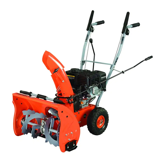
Page 13: Know Your Machine
Two-Stage Snow Blower Operator’s Manual » KNOW YOUR MACHINE FEATURES AND CONTROLS Shear Pin Auger Gearcase Auger Clutch Lever Drive Clutch Lever Scraper Blade Speed Shift Lever Directional Chute Control Drift Cutters (Optional) Discharge Chute Belt Cover Chute Clean-Out Tool Skid Shoes Auger Plastic Skid Shoes (Optional) - Page 14 SPEED SHIFT LEVER Always release the drive clutch lever before changing The speed shift lever has 7 positions: 5 forward speeds. Failure to do so will result in damage to the speeds and 2 reverse. To change speeds, move the snow blower.
- Page 15 Two-Stage Snow Blower Operator’s Manual » twist the tool into the discharge chute to dislodge the blockage. 4. Refasten the clean-out tool to the mounting clip on the rear of the auger housing. 5. Make sure the discharge chute is pointed in a safe direction (no vehicles, buildings, people, or other objects are in the direction of discharge).
-
Page 16: Adjustment
ADJUSTMENT SKID SHOES AUGER CLUTCH AND DRIVE CLUTCH Position the skid shoes based on surface conditions. When auger clutch lever or drive clutch lever is For removal of snow in normal conditions, such as released and in the disengaged position, the cable a paved driveway or sidewalk, place skid shoes in should have very little slack. - Page 17 Two-Stage Snow Blower Operator’s Manual » DRIFT CUTTERS (OPTIONAL) To do so: Drift cutters break up snow drifts that are taller 1. Loose the two nuts which secure the chute bracket than the auger housing and direct the snow into and reposition it slightly.
-
Page 18: Operation
OPERATION FREEWHEELING AND SELF-PROPELLING STARTING AND STOPPING THE ENGINE Use the axle lock pin to lock or unlock the right or left wheel. Lock Before starting the engine, check engine oil level and both wheels to increase traction; unlock one wheel to allow for ensure the engine is served as described in the Engine easier turning of the unit;... - Page 19 Two-Stage Snow Blower Operator’s Manual » TRAVELING SNOW BLOWING TIPS To travel from one work area to another: it falls. 1. Set throttle to slow or part-throttle position. The best time to remove snow is the early morning. At this time 2.
-
Page 20: Maintenance
MAINTENANCE ENGINE Refer to the Engine Operator’s Manual. AUGER GEARBOX factory. Unless there is evidence of leakage or service has been Grease performed on the gearbox, no additional lubricant should be required. If lubricant is required, use GL-5 or GL-6, SAE85-95, EP gear oil lubricant. -
Page 21: Service
Two-Stage Snow Blower Operator’s Manual » SERVICE AUGER BELT REPLACEMENT REPLACEMENT SHEAR PINS A pair of replacement auger shear pins and clevis pins are included If the auger belt becomes worn, oil-soaked, or otherwise damaged, with your snow blower. Store them in a safe place until needed. proceed as follows to replace the belt. - Page 22 4. Carefully pivot the snow blower up and forward so that it rests 2. Remove the two screws that hold the belt cover in place and on the auger housing. set the cover aside. (See Figure 20a) 5. Remove the frame cover from the underside of the snow 3.
- Page 23 Two-Stage Snow Blower Operator’s Manual » 7. Remove and replace belt in the reverse order. FRICTION WHEEL REPLACEMENT Holding down the drive clutch lever will ease If the snow blower fails to drive with the drive clutch engaged, and reinstallation of the belt. performing the clutch control cable adjustment fails to correct the problem, the friction wheel may need to be replaced.
-
Page 24: Storage
6. Remove the other bearing from the left side of the frame by 8. Follow the previous steps in reverse order to reassemble. removing the snap ring. If you only want to replace the rubber ring, proceed as follows: 1. Remove the six screws which secure the friction wheel’s side plates together. -
Page 25: Troubleshooting
Two-Stage Snow Blower Operator’s Manual » TROUBLESHOOTING Problem Cause Remedy 1. Move choke to CHOKE position 1. Choke not in CHOKE position 2. Prime engine as instructed in this 2. Engine not primed manual 3. Wait a few minutes before restarting, do not prime 4. - Page 26 Problem Cause Remedy 1. Drive control cable not adjusted 1. Adjust drive control cable properly Loss of traction drive 2. Replace drive belt 2. Drive belt loose or damaged 3. Replace friction wheel 3. Friction wheel worn 1. Discharge chute clogged 1.
-
Page 27: Parts Diagram
Two-Stage Snow Blower Operator’s Manual » PARTS DIAGRAM Parts Diagram... - Page 28 Parts Diagram...
- Page 29 Two-Stage Snow Blower Operator’s Manual » PARTS LIST Description QTY. Description QTY. Spiral Assembly R Auger Housing Assy Washer Clean-Out Tool Mounting Bracket Big Washer Chute Clean-Out Tool Sealing B20x35x7 Discharge Chute Bolt M6x20 Bolt M8x35 Spring Washer 6 Chute Linkage Plate Flat Washer 6 Lock washer Oil Cup M10x1...
- Page 30 Description QTY. Description QTY. Screw M6x16 Bolt M10x20 Drive Clutch Idler Bolt M8x35 Bolt M8x30 Gearbox Housing Bushing Bracket Drive Clutch Idler Bracket Bolt M8x55 Spacer Spring Bolt M8x40 Frame Cover Engine Bolt M6x35 Spring Washer 10 Nut M6 Engine Washer Washer 10 V-Belt 4LxA675 Supporting Plate...
- Page 31 Two-Stage Snow Blower Operator’s Manual » OPTIONAL DRIFT CUTTERS OPTIONAL SKID SHOES Description QTY. Description QTY. Handle Knob Assembly Plastic Skid Shoe Bolt M8x20 Drift Cutter Parts List...
- Page 32 Tame the Great Outdoors 1850 W Winchester Rd, Suite 106 Libertyville, IL 60048 844-YARDMAX info@yardmax.com (844-927-3629)
Need help?
Do you have a question about the YB5765 and is the answer not in the manual?
Questions and answers
Where can I get a replacement tire