
Related Manuals for YOKOGAWA BT200


Summary of Contents for YOKOGAWA BT200
- Page 1 ® Advanced Test Equipment Rentals www.atecorp.com 800-404-ATEC (2832) TERMINAL User’s Model BT200 BRAIN Manual BRAIN TERMINAL IM 01C00A11-01E 5th Edition Y okogawa Electric Corporation...
-
Page 2: Table Of Contents
2.3 COMPONENT NAME ........2-5 7. TROUBLESHOOTING ........7-1 2.4 DIMENSIONS ..........2-6 3. CONNECTION ..........3-1 APPENDIX A ............. A-1 3.1 PLUGGING THE CABLE INTO THE BT200 .. 3-1 APPENDIX B ............. A-4 3.2 CONNECTION WITH BRAIN SERIES INSTRUMENTS ..........3-2 REVISION RECORD 4. -
Page 3: Introduction
Yokogawa cannot take responsibility for any loss of presents cautionary notes on usage. The contents instrument function that results from repair undertaken display on the BT200 and the items that can be set by independently by the customer. the BT200 depend on the types of instruments used In case of problems, contact the Yokogawa with the BT200. -
Page 4: Precautions
1.1 CHECK THE CONTENTS OF THE PACKAGE The BT200 BRAIN TERMINAL are thoroughly tested at the factory before shipment. When the BT200 units are delivered, visually check to make sure that no damage occurred during shipment. Also check that the... -
Page 5: Precautions In Handling
The unit is not waterproof. Ambient humidity: Cover the unit against water when using it BT200-N00 ... 5 to 95%RH at 40°C (104°F) outdoors while it is raining. (free from condensation) Do not allow the unit to fall into water. - Page 6 Simultaneous communication by BRAIN printout (about 10 hours/1,000 lines). Terminal and DCS. c. Low-voltage indicator • The BT200 turns on its BATTERY indicator (3) POWER SUPPLY when the battery voltage falls. Replace the a. Note on using dry batteries batteries whenever the BATTERY indicator is on.
- Page 7 <Toc> <Ind> <1. PRECAUTIONS> (5) EMC CONFORMITY STANDARDS EN61326, AS/NZS CISPR11 IM 01C00A11-01E...
-
Page 8: Introduction To Bt200
BRAIN instrument (*1). cations, including field instruments, such as differential pressure and pressure transmitters, The 4 to 20 mA DC signal line between the BT200 vortex flow meters, magnetic flow meters and and the BRAIN instrument can be superimposed with a... -
Page 9: What The Bt200 Can Do
Records the setup data on the Print density control Permits controlling the printout density BRAIN instrument connected to the through a utility panel. the print density BT200 into the BT200 s memory in a level can be visually verified from test batch. printout. T0201.EPS... -
Page 10: Specification
Power Supply: Five AA 1.5 V dry alkali batteries (LR6/AM3(N)) Equipment Specifications Dimensions: Applicable Equipment BT200-N00 · · · 228 110 51 mm DPharp Series (9.0 4.3 2.0 inch) ADMAG Series BT200-P00 · · · 321 110 61 mm YEWFLO Series (12.6 4.3 2.4 inch) - Page 11 /CS1 (Note 1) Approval BT200-N00 See Appendix B. (Note 2) T0203.EPS Note 1: Optional Code /CS1 can not be combined with /C1. Note 2: Applicable only for model BT200-N00. PART NUMBERS Item Parts No. with IC clips F9182EA F9182EB with alligator clips...
-
Page 12: Component Name
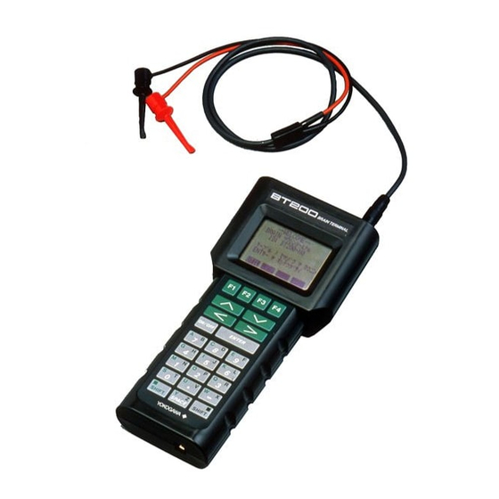
<Toc> <Ind> <2. INTRODUCTION TO BT200> 2.3 COMPONENT NAME Fuigure 2.3 Component Name IM 01C00A11-01E... -
Page 13: Dimensions
<Toc> <Ind> <2. INTRODUCTION TO BT200> 2.4 DIMENSIONS Fuigure 2.4 Dimensions IM 01C00A11-01E... -
Page 14: Connection
BT200 connector and push the cable into position until a click sounds. Note: You cannot plug the connector cable for the BT100 into the BT200, because the BT200 and BT100 have different connector structures. IM 01C00A11-01E... - Page 15 (2) CONNECTION IN RELAY TERMINAL BLOCK There are no dedicated pins for connecting to Figure 3.2.a Connecting the BT200 the BRAIN TERMINAL in the field relay terminal block or in the meter compartment terminal block. In this case, use the cable with the alligator clips.
- Page 16 <Toc> <Ind> <3. CONNECTION > (3) CONNECTION TO SIGNAL CONDITIONER ESC (signal conditioner communication card) or EXT (extension card) is provided with a BRAIN TERMINAL connector (see Figure 3.2.b). A 5-pin connector cable for the BRAIN TERMI- NAL is supplied when the BRAIN TERMINAL comes with /C1 options.
-
Page 17: Bt200 Basic Operations
<Toc> <Ind> <4. BT200 BASIC OPERATIONS > 4. BT200 BASIC OPERATIONS 4.1 KEY LAYOUT AND DISPLAY MENU PANEL Messages MENU BATTERY A:DISPLAY B:SETTING Menu choices C:ADJUST I:CALIBRATION (up to six displayed) Panel title K:TEST M:CHECK DATA HOME Function commands PARAMETER PANEL... -
Page 18: Key Descriptions
<Toc> <Ind> <4. BT200 BASIC OPERATIONS > b) Entering letters (A through Z) 4.2 KEY DESCRIPTIONS Press an alphanumeric key following a shift key to enter the letter shown on the side of the shift key (1) ALPHANUMERIC KEYS AND SHIFT KEYS pressed. - Page 19 <Toc> <Ind> <4. BT200 BASIC OPERATIONS > * Use the function key [F2] to select between * Use the function key [F1] to enter symbols. CAPS CODE uppercase and lowercase (for letters only). The The following symbols will appear in sequence,...
- Page 20 <Toc> <Ind> <4. BT200 BASIC OPERATIONS > (2) FUNCTION KEYS The functions of the function keys depend on the function commands on display. FUNCTION COMMAND LIST (FOR BT200-N00 & BT200-P00) (FOR BT200-P00) Command Function Command Function Displays the ADJ menu...
-
Page 21: Bt200 Function Configuration
<Toc> <Ind> <4. BT200 BASIC OPERATIONS > 4.3 BT200 FUNCTION CONFIGURATION MENU PARAM J:ADJUST C60:SELF CHECK K:TEST GOOD (DPharp) M:MEMO P:RECODE ––WELCOME–– PARAM MENU PARAM BRAIN TERMINAL 01:MODEL C:SETTING C12:HIGH RANGE EJ110-DM BT200 D:AUX SET 1 1000 mmH2O 02:TAG NO. -
Page 22: Basic Operations
(1) TURN THE POWER SWITCH ON OR Startup panel Turn on the BT200, and it comes up with the panel shown below. (The message “Please wait . . . ” will be displayed for seconds after the unit is turned on.) - Page 23 STARTUP PANEL ––WELCOME–– Plug the cable into the instrument and press [ENT]. BRAIN TERMINAL [F1] UTIL → Call a utility panel (See Section 5.3.) BT200 [F2] FEED → Paper feed (BT200-P00) check connection push ENTER key UTIL FEED INITIAL DATA PANEL...
- Page 24 <Toc> <Ind> <4. BT200 BASIC OPERATIONS > (2) DISPLAY PARAMETERS DPharp a) Menu panel operations The menu panel contains a list of up to six menu If the menu choices are blocked (as with DPharp,) choices in each page. Use [<] and [>] to change the the menus are displayed for each block.
- Page 25 <Toc> <Ind> <4. BT200 BASIC OPERATIONS > b) Call the parameter panel MENU INITIAL DATA PANEL J:ADJUST On initial data panel, type [F4] OK or K:TEST PARAM M:MEMO 01:MODEL [ENT] to call the starting [HOME menu P:RECODE EJ110-DM MENU 02:TAG NO.
- Page 26 4-10 <Toc> <Ind> <4. BT200 BASIC OPERATIONS > Helpful hint 1 Helpful hint 2 • Typing letters in a panel allows you to make a direct • Following procedure allows you to make a direct selection of the corresponding menu choices from selection of the parameter.
- Page 27 4-11 <Toc> <Ind> <4. BT200 BASIC OPERATIONS > c) Call the self-check panel Press [F2] DIAG on a parameter panel to call a self- While commands are PARAM A10:OUTPUT check panel. The self-check panel displays self- displayed on panel , type 100.0 %...
- Page 28 4-12 <Toc> <Ind> <4. BT200 BASIC OPERATIONS > (3) CHANGE SETUP DATA To change setup data, select a parameter to change ( – ) from parameter panel and press [ENT] to call setup panel. If you have set a security code with a utility, that code must be entered.
- Page 29 4-13 <Toc> <Ind> <4. BT200 BASIC OPERATIONS > Example 2 Change the unit. Current: mmH SETUP PANEL 3. The setup procedure is PARAMETER PANEL C20:PRESS UNIT complete. 1. Select the parameter to PARAM Paper feed. [F1] FEED C10:TAG NO. change with [ ], [ ], [<] or [>]...
- Page 30 You must to type the security code only once after the BT200 is switched on. Reentry is not needed until you SECURITY CODE SETUP PANEL switch off the BT200.
-
Page 31: Using The Bt200 Functions
(UPLOAD) FUNCTIONS First, it is necessary to copy the settings for a particular instrument into the BT200 in a batch. The items from the SET menu can be copied. 5.1 SETTING UP DATA IN A 1. Connect the BT200 to the... - Page 32 UPLOAD complete (See section 5.2(5).) F3:print data HOME Return to the [F4] ESC PRNT function panel. F0501-2.EPS Because the data is written to the BT200’s nonvolatile F0502-1.EPS memory, it is preserved intact even when the terminal is switched off. IM 01C00A11-01E...
- Page 33 <Toc> <Ind> <5. USING THE BT200 FUNCTIONS > * If the model name is unmatched, the message 3. Check the model name DNLOAD “MODEL mismatch” is displayed. Press [F4] ESC MODEL displayed on panel EJ110-DM return to panel that of the instrument into DOWNLOAD start? which data is downloaded.
-
Page 34: Using Printer Functions (Bt200-P00)
(BT200-P00) 1. Enter new data into the setup C10:TAG NO. panel and press [ENT] to TABC-101 select the setup data The BT200-P00 BRAIN TERMINAL with a printer PFT-001_ verification panel can print in the following modes: CODE CAPS 1. Listing of setup data Prints out old and new versions of the data on the setup panel. - Page 35 <Toc> <Ind> <5. USING THE BT200 FUNCTIONS > (2) PRINTING DISPLAY PARAMETERS (3) PRINTING ALL PARAMETERS FROM A MENU CHOICE 1. Press [F4] PRNT on PARAM A10:OUTPUT parameter panel to change 1. Press [F4] PRNT on PARAM 100.0 % A10:OUTPUT the function commands.
- Page 36 <Toc> <Ind> <5. USING THE BT200 FUNCTIONS > 2. Select ‘4.PRINT ALL DATA’ 4. Press [F3] GO to start FUNC PRINT 1.MENU A:DISPLAY from command panel printing. 2.UPLOAD TO HHT print data in menu press [ENT]. Pressing [ENT] with the 3.DOWNLOAD TO INST...
- Page 37 <Toc> <Ind> <5. USING THE BT200 FUNCTIONS > (5) PRINTING UPLOADED OR DOWNLOADED b) DOWNLOAD DATA following the end of a download, the downloaded a) UPLOAD data can be printed out by following the proce- dural steps similar to printing out uploaded data 1.
-
Page 38: Offline Functions
<Toc> <Ind> <5. USING THE BT200 FUNCTIONS > (6) PRINTING A LIST OF SELF-CHECK INFOR- 5.3 OFFLINE FUNCTIONS MATION Call The Offline Menu (UTILITY PANEL) 1. Press [F2] DIAG on the PARAM C10:TAG NO. parameter panel to call self- TABC-101... - Page 39 (1) ID (Identification Code) SETUP (2) LANGUAGE SELECTION (BETWEEN ENGLISH AND JAPANESE) Each BT200 BRAIN TERMINAL is assigned an ID a) English to Japanese (identification code) to identify itself from other terminals. The ID is displayed on the startup panel 1.
- Page 40 5-10 <Toc> <Ind> <5. USING THE BT200 FUNCTIONS > b) Japanese to English Return to panel [F3] NO [F4] OK Go to panel 1. Press [F1] to select the unility panel in Japanese. Start [F4] ESC UTILITY 1.ID communication, 2.SECURITY CODE returning to the 3.LANGUAGE SELECT...
- Page 41 <5. USING THE BT200 FUNCTIONS > (3) LCD CONTRAST CONTROL b) CONTROLLING THE LCD ON THE UTILITY PANEL The BT200 features software capability to control the LCD contrast. There are two ways to control the Select ‘4. LCD CONTRAST’ from the utility LCD contrast.
-
Page 42: Maintenance
Replace the batteries with new batteries having a specified voltage (1.5 V) as soon as possible. The BT200 could stop operating any moment if you CAUTION continue to use it without replacing the batteries. For intrinsically safe type, the battery used in Prerequisites : One Phillips screwdriver BT200 must be as follows. - Page 43 <Toc> <Ind> <6. MAINTENANCE > Manufacture Model Type Voltage DURACELL MN1500 Alkaline- 1.5 V (PC1500) manganese Figure 6.1.a Removing Screws IM 01C00A11-01E...
-
Page 44: Loading Roll Paper
(5) Lead the roll paper through slit c in the cover and close the cover. (6) Switch on the BT200 and press [F2] FEED on the startup panel. Make sure that the roll paper is fed correctly. Figure 6.2... -
Page 45: Troubleshooting
(3) Wiring diagram 2. THE DISPLAY IS ERASED AUTOMATICALLY (4) Details of the problem The autopower-off feature of the BT200 will switch it (5) Checks made and the results off automatically when no key access is made for five (6) Other related information minutes or longer. - Page 46 (Figure 7.2) (1) Are the BT200 and the instrument wired as in- structed in the relevant instruction manuals? 6. SELF CHK ERROR INDICATION IS ON Check again to make sure.
- Page 47 <Toc> <Ind> <7. TROUBLESHOOTING> Figure 7.2 Connector pin numbers Figure 7.3 Wiring IM 01C00A11-01E...
-
Page 48: Appendix A
<Toc> <Ind> <APPENDIX> APPENDIX A A) SETTING A SECURITY CODE To register a security code in the BT200 as shipped, follow these steps. 1. Setting and Changing SECURITY CODE The BT200 is shipped without a security code set. You 1. Select ‘2. SECURITY CODE’... - Page 49 <Toc> <Ind> <APPENDIX> 2. Canceling a SECURITY CODE B) CHANGING THE SECURITY CODE To cancel a registered security code, follow these steps. To change a security code after it has been regis- tered, follow these steps. 1. Select the security panel SECURITY old SECURITY CODE Type the old current security...
- Page 50 <Toc> <Ind> <APPENDIX> 3. When You Forget the SECURITY CODE When you forget the security code that has been registered and register a new security code from the beginning, follow these steps. 1. Call security panel SECURITY old SECURITY CODE type‘RSET’.
-
Page 51: Appendix B
B, C & D Hazardous Locations. – – • Temperature Class: T4 – – • Ambient Temperature: -15 to 55°C Electrical Parameters • BT200 Intrinsically Safe Apparatus Parameters BT200 The Maximum Input Voltage Vmax(in)=30V – The Maximum Input Current Imax(in)=165mA F0B01.EPS... - Page 52 NONHAZARDOUS” and “USE IN ACCOR- DANCE WITH INSTRUCTION MANUAL IM Installation 1C0A11-01E”. • All wiring shall comply with Canadian Electrical • The battery used in BT200 must be as follows. code Part I and Local Electrical Codes. Manufacture Model Type Voltage •...
- Page 53 <Toc> <Ind> <REVISION RECORD> REVISION RECORD Title: Model BT200 BRAIN TERMINAL Manual No.: IM 01C00A11-01E Edition Date Page Revised Item Edition Date Page Revised Item 1994 New Publication 2002 Revised a book in a new format. July · Delete ‘EMC CONFORMITY...
Need help?
Do you have a question about the BT200 and is the answer not in the manual?
Questions and answers