Aiwa AZG-1 Service Manual
Cd-r/rw mechanism
Hide thumbs
Also See for AZG-1:
- Service manual (21 pages) ,
- Service manual (21 pages) ,
- Service manual (18 pages)

Related Manuals for Aiwa AZG-1


Summary of Contents for Aiwa AZG-1
- Page 1 AZG-1 English SERVICE MANUAL CD-R/RW MECHANISM BASIC CD MECHANISM:KSM-880CAB TYPE ZD8RD YZD8RMDJM ZD8RMDJM ZD8RDNDM YKZD8RDF ZD8RDM YZD8RDM ZD8RN1DM YZD8RDJM S/M Code No. 09-001-335-3N6...
-
Page 2: Protection Of Eyes From Laser Beam During Servicing
PROTECTION OF EYES FROM LASER BEAM DURING SERVICING This set employs laser. Therefore, be sure to follow carefully the CAUTION instructions below when servicing. Use of controls or adjustments or performance of procedures other than those specified herein may result in hazardous WARNING! radiation exposure. - Page 3 How to Adjust the Rotating Phase of the Gear, Main Cam 1) Push down the hooking catch of the CHAS. MECH, and remove the TRAY. 2) Align the arrow mark of the Gear, Main Cam with the black round mark of the CHAS, MECHA as shown below. 3) Confirm that the Slide, Mech Cam is located in the right position, then insert the TRAY gently.
-
Page 4: Electrical Main Parts List
ELECTRICAL MAIN PARTS LIST REF. NO PART NO. KANRI DESCRIPTION REF. NO PART NO. KANRI DESCRIPTION C109 87-010-992-080 C-CAP,S 0.047-25 B C110 87-010-196-080 CHIP CAPACITOR,0.1-25 87-A21-381-040 C-IC,LA9235M <YKZD88RDF,ZD8RD> 87-A21-556-010 C-IC,LC78641E C110 87-010-196-020 CHIP CAPACITOR,0.1-25 87-A21-414-010 IC,BA5927S <EXCEPT YKZD88RDF,ZD8RD> C111 87-010-260-080 CAP, ELECT 47-25V C112 87-010-197-020... -
Page 5: Chip Resistor Part Code
REF. NO PART NO. KANRI DESCRIPTION REF. NO PART NO. KANRI DESCRIPTION C207 87-010-196-080 CHIP CAPACITOR,0.1-25 CN202 87-A60-130-010 CONN,5P V <YKZD88RDF,ZD8RD> CN501 84-ZG1-647-010 CONN ASSY,2P C301 87-010-382-080 CAP, ELECT 22-25V <EXCEPT ZD8RN1DM,ZD8RNDM> C302 87-010-196-020 CHIP CAPACITOR,0.1-25 CN601 87-009-345-010 CONN,2P PH V <EXCEPT YKZD88RDF,ZD8RD>... -
Page 6: Transistor Illustration
TRANSISTOR ILLUSTRATION E C B 2SA1235F 2SA1980Y/G 2SK2158 2SC3052F KTA1266GR DTC124XK... -
Page 7: Block Diagram
BLOCK DIAGRAM RVDD... - Page 8 WIRING TO MOTOR C.B PIN3...
-
Page 9: Schematic Diagram
SCHEMATIC DIAGRAM IC101 LC78641E M201 MOVE 3.6V VDD/2V... -
Page 10: Test Mode
TEST MODE 1. How to Start the CD Test Mode *1 ..When the focus search keeps running for 10 minutes or longer continuously, the driver IC heats up, and the protective circuit works so that the machine may stops operating. While pressing the CD function key, connect the AC power plug to wall outlet. -
Page 11: Ic Block Diagram
WAVE FORM IC BLOCK DIAGRAM IC, BA5927S IC201 • (IN6-R) VOLT/DIV: 500mV TIME/DIV: 200mS IC201 ª (IN6-F) 1.6Vp-p 1.6Vp-p Between CN202 1 and 2 VOLT/DIV: 1V (2 Pin: 0 Level) TIME/DIV: 200mS IC101 % (FE) VOLT/DIV: 500mV TIME/DIV: 2mS IC, LA9235M 1.75Vp-p IC101 ^ (TE) VOLT/DIV: 200mV... - Page 12 IC DESCRIPTION IC, LC78641E Pin No. Pin Name Description Pin No. Pin Name Description PDO1 Internal VCO control phase comparator output pin. (Pull down) EFLG C1, C2 error correction monitor pin. (Not connected) Internal VCO control phase comparator output pin. TEST Test input pin.
- Page 13 Pin No. Pin Name Description Synchronization signal detection output pin. FSEQ Outputs a high level when the synchronization signal detected from the EFM signal and the internally generated synchronization signal agree. (Not connected) Defect pin. Which becomes an input pin after reset and can be controlled externally. DEFECT This becomes the defect monitor pin under control by command.
-
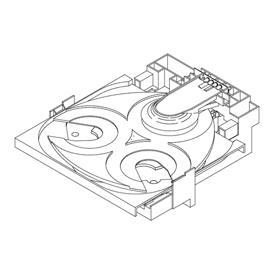
Page 14: Mechanical Exploded View
MECHANICAL EXPLODED VIEW 1/1 P.C.B P.C.B P.C.B CUSHION,CD880 CUSHION,CD880... -
Page 15: Mechanical Parts List
MECHANICAL PARTS LIST 1/1 REF. NO PART NO. KANRI DESCRIPTION REF. NO PART NO. KANRI DESCRIPTION 1 84-ZG1-225-010 BELT,SQ1.0-63.3 20 81-ZG1-255-110 PLATE,MAGNET MK2<EXCEPT ZD8RN1DM> 2 84-ZG1-673-010 F-CABLE,5P 1.25 210MM BLACK N 21 83-ZG3-604-010 RING,MAG 2 <EXCEPT ZD8RN1DM,ZD8RNDM> 22 83-ZG3-213-010 LVR,SW 2 84-ZG1-672-010 F-CABLE,5P 1.25 210MM WHITE N 23 84-ZG1-208-210... -
Page 16: Cd Mechanism Exploded View
CD MECHANISM EXPLODED VIEW 1/1 P.C.B CD MECHANISM PARTS LIST 1/1 REF. NO PART NO. KANRI DESCRIPTION REF. NO PART NO. KANRI DESCRIPTION 1 91-564-722-110 CONN,PIN 6P 8 92-647-742-010 SPRING COMPRESSION 2 91-572-085-110 LEAF SWITCH 9 93-321-813-110 POLI WASHER 3 9X-264-655-010 SL MOTORR ASSY 10 92-647-407-010 GEAR A... -
Page 17: Mechanical Section
REFERENCE NAME LIST ELECTRICAL SECTION MECHANICAL SECTION DESCRIPTION REFERENCE NAME DESCRIPTION REFERENCE NAME ANTENNAS ADHESHIVE SHEET ADHESHIVE CHIP AZIMUTH C-CAP CAP, CHIP BAR-ANT BAR-ANTENNA C-CAP TN CAP, CHIP TANTALUM BATTERY C-COIL COIL, CHIP BATT BATTERY C-DI DIODE, CHIP BEARING C-DIODE DIODE, CHIP BUTTON C-FET... - Page 18 2–11, IKENOHATA 1–CHOME, TAITO-KU, TOKYO 110-8710, JAPAN TEL:03 (3827) 3111 Printed in Singapore 0251431...
Need help?
Do you have a question about the AZG-1 and is the answer not in the manual?
Questions and answers