Advertisement
Quick Links
QQ
3 7 63 1515 0
SERVICE MANUAL
TE
L 13942296513
CD MECHANISM
www
.
http://www.xiaoyu163.com
TYPE
ZD5GNC
ZD5GNC1
YZD5GNCC1
ZD9GNC1
YZD9GNCC1
x
ao
u163
y
i
S/M Code No. 09-023-353-2N8
http://www.xiaoyu163.com
BZG-2
2 9
8
Q Q
3
6 7
1 3
1 5
BASIC CD MECHANISM : KSM-213 RSCM
BASIC CD MECHANISM
KSM-213 RSCM
KSM-213 RSCM
KSM-213 RSCM
BZG-6 YANC
BZG-6 YANC
co
.
English
9 4
2 8
0 5
8
2 9
9 4
2 8
BZG-6 YANC
m
9 9
9 9
Advertisement

Related Manuals for Aiwa BZG-2


Summary of Contents for Aiwa BZG-2
- Page 1 BZG-2 English 3 7 63 1515 0 SERVICE MANUAL L 13942296513 BASIC CD MECHANISM : KSM-213 RSCM CD MECHANISM BZG-6 YANC TYPE BASIC CD MECHANISM ZD5GNC KSM-213 RSCM ZD5GNC1 KSM-213 RSCM YZD5GNCC1 KSM-213 RSCM ZD9GNC1 BZG-6 YANC YZD9GNCC1 BZG-6 YANC u163 S/M Code No.
-
Page 2: Protection Of Eyes From Laser Beam During Servicing
http://www.xiaoyu163.com PROTECTION OF EYES FROM LASER BEAM DURING SERVICING 3 7 63 1515 0 This set employs laser. Therefore, be sure to follow carefully the CAUTION instructions below when servicing. Use of controls or adjustments or performance of procedures other than those specified herein may result in hazardous WARNING! radiation exposure. - Page 3 http://www.xiaoyu163.com Precaution to replace Optical block (BZG-6 YANC) 3 7 63 1515 0 (PXR-104X-BP-0101) PICK-UP Assy PWB Body or clothes electrostatic potential could ruin laser diode in the optical block. Be sure ground body and workbench, and use care the clothes do not touch the diode.
- Page 4 http://www.xiaoyu163.com Precaution to replace Optical block (KSM-213RSCM) 3 7 63 1515 0 (KSS-213R) Body or clothes electrostatic potential could ruin laser diode in the optical block. Be sure ground body and workbench, and use care the clothes do not touch the diode. 1) After the connection, remove solder shown in the right figure.
- Page 5 http://www.xiaoyu163.com How to Adjust the Rotating Phase of the Gear, Main Cam 3 7 63 1515 0 1) Pull out the FFC from the CD MAIN C.B, and then remove the TRAY, ASSY. 2) Set the GEAR, MAIN CAM so that the marking on it is positioned at the protrusion of the CHAS, MECHA as shown in the drawing below.
- Page 6 Components marked S and O are designated as spare parts for service and will be stocked at the spare parts centers. Components marked X and R are not designated as spare parts for after sales service, and will not be stocked at the spare parts centers. UNIT-NAME ! C REF-NO PARTS-NO PARTS-NAME SUFFIX&MODEL BZG-2 BZG-2 BZG-2 BZG-2 BZG-2 ZD5GNC...
- Page 7 Components marked S and O are designated as spare parts for service and will be stocked at the spare parts centers. Components marked X and R are not designated as spare parts for after sales service, and will not be stocked at the spare parts centers. UNIT-NAME ! C REF-NO PARTS-NO PARTS-NAME SUFFIX&MODEL BZG-2 BZG-2 BZG-2 BZG-2 BZG-2 ZD5GNC...
- Page 8 Components marked S and O are designated as spare parts for service and will be stocked at the spare parts centers. Components marked X and R are not designated as spare parts for after sales service, and will not be stocked at the spare parts centers. UNIT-NAME ! C REF-NO PARTS-NO PARTS-NAME SUFFIX&MODEL BZG-2 BZG-2 BZG-2 BZG-2 BZG-2 ZD5GNC...
- Page 9 http://www.xiaoyu163.com ELECTRICAL PARTS LIST-4/4 3 7 63 1515 0 • Regarding connectors, they are not stocked as they are not the initial order items. The connectors are available after they are supplied from connector manufacturers upon the order is received. CHIP RESISTOR PART CODE Chip Resistor Part Coding Figure...
- Page 10 http://www.xiaoyu163.com TRANSISTOR ILLUSTRATION-1/1 3 7 63 1515 0 E C B RT1N 141C 2SA19790/Y 2SC5343Y 2SA1980G L 13942296513 u163 -10- http://www.xiaoyu163.com...
- Page 11 http://www.xiaoyu163.com BLOCK DIAGRAM-1/1 3 7 6 3 1 5 1 5 0 1 3 9 4 2 2 9 6 5 1 3 w w w u 1 6 3 -11- http://www.xiaoyu163.com...
- Page 12 http://www.xiaoyu163.com WIRING-1/2 (3CD) 3 7 6 3 1 5 1 5 0 1 3 9 4 2 2 9 6 5 1 3 w w w u 1 6 3 -12- http://www.xiaoyu163.com...
- Page 13 http://www.xiaoyu163.com SCHEMATIC DIAGRAM-1/1 3 7 6 3 1 5 1 5 0 1 3 9 4 2 2 9 6 5 1 3 w w w u 1 6 3 -13- http://www.xiaoyu163.com...
- Page 14 http://www.xiaoyu163.com WIRING-2/2 (T-T/MOTOR) 3 7 63 1515 0 L 13942296513 u163 -14- http://www.xiaoyu163.com...
- Page 15 http://www.xiaoyu163.com WAVE FORM-1/1 3 7 63 1515 0 IC201 (OUT6-) VOLT/DIV: 500mV IC101 ( RES) VOLT/DIV: 1V TIME/DIV: 200mS TIME/DIV: 10mS IC101 (VDD5) IC201 (OUT6+) IC101 (XOUT) (POWER ON) 1.6Vp-p 5.2Vp-p 6Vp-p 1.6Vp-p 1.2Vp-p Between CN202 VOLT/DIV:1V Pin: 0 Level) TIME/DIV: 200mS IC101 (RES)
- Page 16 http://www.xiaoyu163.com IC BLOCK DIAGRAM-1/1 IC, BA5927S 3 7 63 1515 0 L 13942296513 u163 -16- http://www.xiaoyu163.com...
- Page 17 http://www.xiaoyu163.com IC DESCRIPTION-1/1 (LC78646)-1/3 3 7 63 1515 0 Pin No. Pin Name Description SLCO Control output. SLCIST Slice level control SLCO output current adjustment resistor connection pin. EFMIN RF signal input pin. RF monitor pin. RFVDD — RF power supply pin. RFVSS —...
- Page 18 http://www.xiaoyu163.com IC DESCRIPTION-1/1 (LC78646)-2/3 3 7 63 1515 0 Pin No. Pin Name Description LVDD — Lchannel power supply pin. LCHO L channel D/A converter L channel output pin. LVSS — L channel ground pin. Must be connected to 0V. RVSS —...
- Page 19 http://www.xiaoyu163.com IC DESCRIPTION-1/1 (LC78646)-3/3 3 7 63 1515 0 Pin No. Pin Name Description 73, 74 PD01, 2 Phase comparison output pin 1, 2 to control built-in VCO. VVSS — Built -in VCO GND pin. Must always be connected to 0V. PCKIST Resistor connection pin to set current for PD01 and 02 outputs.
- Page 20 http://www.xiaoyu163.com CD ELECTRICAL MEASUREMENT 3 7 63 1515 0 • Perform the measurement after the machine enters the test mode. • Place the CD mechanism horizontally level. • Equipment and tools required Measuring equipment: Oscilloscope (Use the probe of 10:1) Digital Multimeter (Use it in the DC Volt range.) Jitter meter (Kikusui 6235 or equivalent) Test disc:...
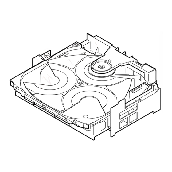
- Page 21 CD MECHANISM EXPLODED VIEW-1/2 (BZG-2) 3 7 63 1515 0 L 13942296513 u163 -21- http://www.xiaoyu163.com...
- Page 22 CD MECHANISM PARTS LIST -1/2 (BZG-2) = ! SAFTY PARTS = Components marked All components used on this model at the production line are shown in this service manual. 3 7 6 3 1 5 1 5 0 However, please note that not all components will be available as spare parts for after-sales service.
-
Page 23: Color Name Table
http://www.xiaoyu163.com 3 7 63 1515 0 COLOR NAME TABLE Basic color symbol Color Basic color symbol Color Basic color symbol Color Black Cream Orange Green Gray Blue Transparent Blue Gold Pink Silver Titan Silver Brown Violet White Transparent White Yellow Transparent Yellow Metallic Blue Light Blue... - Page 24 http://www.xiaoyu163.com CD MECHANISM EXPLODED VIEW-2/2 (BZG-6 YANC) 3 7 63 1515 0 L 13942296513 u163 -24- http://www.xiaoyu163.com...
- Page 25 http://www.xiaoyu163.com CD MECHANISM PARTS LIST-2/2 (BZG-6 YANC) 3 7 63 1515 0 REF. NO PART NO. KANRI DESCRIPTION 1 83-ZG2-262-010 CHAS ASSY,E3 2 87-A92-037-010 2M PICKUP,PXR-104X-BP-0101 3 83-ZG2-235-010 0E GEAR,A3 4 83-ZG2-236-010 0E GEAR,MOTOR 3 5 83-ZG2-205-210 0E GEAR,B 6 83-ZG2-253-110 0E SHAFT,SLIDE 5 A 87-261-032-210 0E V+2-3 L 13942296513 u163...
- Page 26 http://www.xiaoyu163.com 3 7 63 1515 0 L 13942296513 u163 2-11, IKENOHATA 1-CHOME, TAITO-KU, TOKYO 110-8710, JAPAN TEL:03 (3827) 3111 0251431 http://www.xiaoyu163.com...
Need help?
Do you have a question about the BZG-2 and is the answer not in the manual?
Questions and answers