Table of Contents
Advertisement
Quick Links
Advertisement
Table of Contents

Related Manuals for IP-COM SE3100

Summary of Contents for IP-COM SE3100
-
Page 2: Copyright Statement
IP-COM does not assume any liability that may occur due to the use or application of the product or circuit layout(s) described herein. Every effort has been made in the... -
Page 3: Intended Readers
Preface Thank you for purchasing this IP-COM product! Reading this User Guide will be helpful for configuring, managing and maintaining this product. Intended Readers This User Guide is intended for those who have basic technical knowledge related to the Internet and network terminology. -
Page 4: Technical Support
Data Download Go to our IP-COM website www.ip-com.com.cn to download the latest data and manual. Technical Support Website: www.ip-com.com.cn Tel: (86 755) 2765 3089 Email: info@ip-com.com.cn... -
Page 5: Table Of Contents
Contents Chapter 1 Product Overview ......................... 1 Overview .............................. 1 Features ..............................1 Package Contents ..........................1 Appearance ............................2 Front Panel ............................2 Back Panel............................3 Label ..............................4 Chapter 2 Device Installation ........................ 5 Installation Notes..........................5 Safety Alert ............................5 Environmental Requests ........................ - Page 6 System Status ............................. 14 Device Info ............................. 14 WAN Statistics ..........................14 Clients Statistics ..........................15 Network Settings ..........................15 LAN Settings..........................15 WAN Settings ..........................16 DHCP Server ..........................16 Load Balance ..........................18 Bandwidth Control ..........................19 Portal Authentication .......................... 21 Portal Authentication ........................
- Page 7 VPN Clients ........................... 47 VPN Passthrough ........................... 49 Advanced Settings ..........................49 Network Diagnostics ........................49 Static Routing ..........................52 Port Forwarding ..........................55 Remote WAN ..........................57 WAN Ping ............................58 DDNS ............................. 59 Page Timeout..........................61 System Tools ............................61 Date &...
-
Page 8: Chapter 1 Product Overview
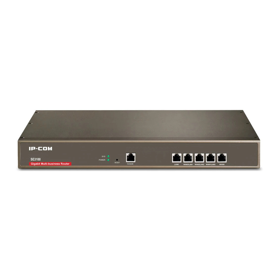
Chapter 1 Product Overview Overview IP-COM SE3100 is a Gigabit business-class router that has integrated multi-WAN capability, load balance, bandwidth control, portal authentication, and VPN settings. There are three LAN/WAN multiplexing ports which can be configured as LAN ports, or WAN ports to suit your needs. -
Page 9: Appearance
Appearance Front Panel LED Color Status Description Solid The device is receiving electrical power. POWER Green The device is malfunctioning or not connected to the power supply. Slow flashing: Device system is working properly. Flashing Fast flashing: The system is starting up or erased internal storage (NAND-flash). -
Page 10: Back Panel
When the device stays on standby: Press this button for five~fifteen seconds and release it; in approximately one minute, the device will reboot and restore to its factory defaults. Press this button for at least sixteen seconds and release it; in approximately one minute, the device will reboot and clear its internal storage. -
Page 11: Label
Label ① Model No. of the device ② LAN IP of the device, used to access the device‟s Web management interface ③ Username and password to log in to the device. ④ AC input requirement ⑤ Serial number (SN) of the device. This is required if the device is sent back for maintenance. -
Page 12: Chapter 2 Device Installation
Position the device away from a strong electrical current. NOTE There is an IP-COM seal on one of the cover screws. The seal must remain unbroken. The user should not break the seal as this will void the warranty. Environmental Requests Temperature/Humidity ... -
Page 13: Lightning Protection
Anti-static Precautions To protect the device from static electricity harm, Keep the device in a clean and clear environment. Clean the device regularly. Properly ground the device to efficiently dissipate static electricity. Lightning Protection To protect the device from a lightning strike or power surge, ... -
Page 14: Installation
Installation The device can be installed either in a rack or a flat surface (desktop/workbench). A. Rack-mounting You can install the device in a standard 19-inch rack with the accessories (L-shaped brackets and screws) that come in the box. ❶ Install the rack, in a location ensuring it is both stable and level. -
Page 15: Physical Connection
❸ Gently place the device upright on the desktop. Physical Connection ❶ Plug the Internet access cable from your ISP into the WAN port on the device. ❷ Connect the device to a switch via LAN port using an Ethernet cable. - Page 16 ❸ Connect other devices such as APs, servers or PCs, to the switch. ❹ Inspect your cabling, referring to the connection topology below. Connect the device to the power supply with the included power cord.
- Page 17 ❺ After the device is rebooted, the device will initialize its default settings. Check LEDs status, which should be displayed successively as the following: All LEDs (POWER, Link/Act and Speed LEDs) except "SYS" LED will light up and the system will start a self-test.
-
Page 18: Chapter 3 Login
Chapter 3 Login Log in to the Device If you are setting up the device for the first time, the default parameters are needed for you to log in to the device‟s Web manager. The default parameters are: Item Details LAN IP Address 192.168.0.252 Username... - Page 19 ❸ Launch your Web browser (Google Chrome is recommended); type 192.168.0.252 in the address bar and hit Enter. ❹ This will direct you to the device login page, prompting you to enter the username (default: admin) and password (default: admin), and hit Enter. NOTE Different Internet browsers may show different screen details.
-
Page 20: Web Management
For more functions, see Chapter 4 More Functions. Web Management Item Description Here you can select function menus. The results will be displayed on Navigation Bar configuration zone. Configuration Zone Here you can set the device and view the configuration. NOTE Grey sections on the page cannot be modified in their current status, or they're unavailable. -
Page 21: Chapter 4 More Functions
Chapter 4 More Functions System Status This section can help you get to know more about device info, WAN statistics and client statistics. Device Info Click System Status > Device Info to enter page below where you can view the device info, including interface status, system status, LAN info and WAN info. -
Page 22: Clients Statistics
Clients Statistics Click System Status > Clients Statistics to enter page below where you can view real-time traffic statistics of connected hosts. Network Settings This section instructs you on setting up your device to the Internet. LAN Settings To configure the LAN IP address for the device, click Network Settings > LAN Settings to enter page below: NOTE 1. -
Page 23: Wan Settings
WAN Settings This page allows you to select the total number of WAN ports you prefer to use and configure the WAN Network for the device. By default, only WAN 0 is the WAN port (Note that WAN1/LAN3, WAN2/LAN2, WAN3/LAN1 are LAN/WAN multiplexing ports). You can select the number of WAN ports from the WAN ports drop-down menu. - Page 24 To disable the DHCP server, click the icon directly; to delete the DHCP parameters you‟ve created, click the icon ; if you have deleted the DHCP parameters, click Add to add the only one rule for its DHCP server; to edit the DHCP parameters, click the icon to enter page below: ...
-
Page 25: Load Balance
End IP: Enter the end IP address to make a range for the DHCP server to assign dynamic IPs. Subnet Mask: Enter the Subnet Mask. The default subnet mask is 255.255.255.0. Gateway: It is recommended to enter the IP address of the LAN port of the device. ... -
Page 26: Bandwidth Control
Bandwidth Control This section will assist in prioritizing your network bandwidth usage, to assure a smooth streaming experience for surfing the Internet and online gaming. Click Bandwidth Control to enter page below: Total Egress Bandwidth Config Total egress bandwidth is the bandwidth you have introduced. It is used as the basis of bandwidth division when there is no flow policy. - Page 27 Remark: Description of the group of IPs or accounts. Control Type: The device support bandwidth control based on IP range and accounts. When IP is selected, you need to specify the IP range (start IP and end IP). When Account is selected, you have to enable portal authentication.
-
Page 28: Portal Authentication
can get to. Time & Date: Enter the effective time and date of the policy. Portal Authentication In this section, you can configure portal authentication settings for your device. Portal Authentication This page allows you to enable the portal authentication function and create the accounts for portal authentication. -
Page 29: Advertisement
❶ User: Create the login user account here. ❷ Password: Set the login password for the user account you‟ve created. ❸ Time Type: Select the time type for your account. When you select Time Point, please enter a time point such as 2016-10-10 18:00 in the field below. When the account is authenticated, the account will expire at 2016-10-10 18:00. -
Page 30: Online User
Select Image: Select image to import to the device for the redirect page. The image should be less than 256KB and 800*400px jpeg/jpg/png/gif is recommended Edit Box: Here you can write the message that appears when users log in to the redirect page successfully. -
Page 31: Vpn Settings
VPN Settings VPN (Virtual Private Network) is a private network established via the public network, generally via the Internet. However, the private network is a logical network without any physical links, so it is called Virtual Private Network. VPN, a technology which will not expose the private data to all users on the Internet, allows employees to securely access their company's intranet while traveling outside the office. - Page 32 PPTP Server: Check Enable to enable the PPTP server. WAN Port: Select the WAN port on which to enable the PPTP server. This port‟s IP address is the PPTP server address of the PPTP client. Authentication Type: Specify the encryption type for PPTP tunnel. ...
-
Page 33: Pptp Client
Address Type: Do not change the default setting (Dynamic IP) unless necessary. When Dynamic IP is selected, the PPTP client will obtain an IP address automatically from the PPTP server. When Manual is selected, you need to specify an IP address manually for the PPTP client. -
Page 34: L2Tp Server
Username: Enter the user name you‟ve configured on the PPTP server. Password: Enter the password you‟ve configured on the PPTP server. Remote IP Segment: Set the internal IP segment of the remote PPTP server. Remote Subnet Mask: Set the internal subnet mask of the remote PPTP server. NOTE MPPE is not supported for the PPTP Client function of this router. -
Page 35: L2Tp Client
User: Set the account name of L2TP tunnel. Password: Set the password of L2TP tunnel. Remark: Descriptions of the L2TP user (optional). IP Address: Do not change the default setting (Dynamic IP) unless necessary. When Dynamic IP is selected, the L2TP client will obtain an IP address automatically from the L2TP server. -
Page 36: Application Example Of Pptp/L2Tp
There is a company based in Place A, but has a branch office in Place B. Staffs both in the headquarters and its branch need to share their internal resources securely. Assume that the VPN routers in Place A and Place B are SE3100 and verify that the two SE3100 can access the Internet successfully. - Page 37 Click Save to save your settings. NOTE In this example, SE3100, as the PPTP client, does not support MPPE. Thus, do not check the MPPE option. If a windows operation system is used as the PPTP client, you can check MPPE.
- Page 38 Step 2: Click Add to add a PPTP user: ❶ Set the PPTP user name, say test. ❷ Set the PPTP password, say test. ❸ Give a remark for the PPTP user. ❹ Select the address type (Recommended: Dynamic IP). ❺...
- Page 39 Configurations on the SE3100 in the branch ❶ On the web UI of SE3100 in the branch, click VPN Settings > PPTP Client to configure PPTP client settings. ❷ Check Enable Client. ❸ Select WAN0 as the port for PPTP client.
- Page 40 Verification Method 1: On the web UI of SE3100 in the headquarters, click VPN Settings > VPN Clients to view the PPTP Client List. If the PPTP client negotiates with the PPTP server successfully, PPTP client info will be displayed here.
-
Page 41: Ipsec Settings
IPSec Settings IPsec (IP Security) is a set of services and protocols defined by IETF (Internet Engineering Task Force) to provide high security for IP packets and prevent attacks. To ensure a secured communication, the two IPsec peers use IPsec protocol to negotiate the data encryption algorithm and the security protocols for checking the integrity of the transmission data, and exchange the key to data de-encryption. - Page 42 Enable: check it to enable the IPsec function. WAN: Specify the local WAN port for this Policy. The "Remote Gateway" of the remote router should be set to the IP address of this WAN port. Connection Name: Set a name for IPsec connection for identification. ...
- Page 43 When X.509 is selected, please ensure that certificates of the local router and the remote router are the same. For settings of the certificate, see Certificates. When the Negotiation Type is Auto, the entire negotiation process will be divided into 2 periods: In Period 1, the two sides will negotiate to exchange security proposals, like integrity verification algorithm and encryption algorithm, and establish an ISAKMP (Internet Security Association and Key Management Protocol) SA (Security Association) so that more info in Period 2 can be...
- Page 44 Mode: Set the exchange mode for the negotiation in Period 1. The exchange mode must be identical with its remote one. Two modes are available here. In Main mode, the two sides exchange packets a lot. As this mode provides identification protection, it is suitable for higher identification protection.
- Page 45 PFS: Select the PFS (Perfect Forward Security) to enhance security. PFS configurations on both sides should be identical. With PFS function, IPsec Server and Client negotiate to create a new key in Period 2. As it is independent of the key created in Period 1, this key can be secure even when the key in Period 1 is de-encrypted.
- Page 46 As for descriptions of parameters on the page above, see Negotiation Type --- Auto. ESP Encryption Algorithm: Select ESP encryption algorithm for ESP security protocol. The following encryption algorithms are supported on this router. DES: DES (Data Encryption Standard) encrypts a 64-bit (the last 8-bit of 64-bit is used for parity check) block of plain text with a 56-bit key.
-
Page 47: Application Example Of Ipsec
There is a company based in Place A, but has a branch office in Place B. Staff both in the headquarters and its branch need to share their internal resources securely. Assume that the VPN routers in Place A and Place B are SE3100 and verify that the two SE3100 can access the Internet successfully. - Page 48 Configurations on the SE3100 in the headquarters ❶ Click VPN Settings > IPsec Settings and click Add to configure IPsec parameters (Assume that the negotiation type is Auto and the authentication type is Shared-Key). ❷ Check Enable and select WAN0 as the WAN port on which to enable the IPsec server.
- Page 49 shown above. For settings of certificates, see Certificates. When the negotiation type is Manual, please verify that encryption key and authentication keys on both the IPsec server and IPsec client are identical, and outcoming SPIs and incoming SPIs are opposite.
- Page 50 When IPsec negotiation completes, you cannot directly edit IPsec settings. If necessary, click the button to disable IPsec settings first, and then edit it. Configurations on the SE3100 in the branch ❶ Click VPN Settings > IPsec Settings and click Add to configure IPsec parameters (Assume that the negotiation type is Auto and the authentication type is Shared-Key).
- Page 51 ❸ Set a connection name, say Client. ❹ Specify the remote gateway, say 1.1.1.20. ❺ Specify the remote IP segment, say 192.168.20.0/24. And the Local IP Segment will be displayed as 192.168.30.0/24 automatically. ❻ Set a pre-shared key, say 12345678. ❼...
- Page 52 When configurations are completed, the following actions are allowed: Click the button to disable IPsec settings, and click the button to enable IPsec settings. Click the button to edit IPsec settings. Click the button to delete IPsec settings. NOTE When IPsec negotiation completes, you cannot directly edit IPsec settings.
-
Page 53: Certificates
Verification Method 1: On the web UI of SE3100 in the headquarters, click VPN Settings > VPN Clients to view the IPsec Client List. If the IPsec client negotiates with the IPsec server successfully, IPsec client info will be displayed here. -
Page 54: Vpn Clients
❶ On the local router, generate a local certificate, click Save to Device and click download the certificate. Meanwhile, import the certificate to “Remote Certificates” of the remote router and click Save to Device. ❷ On the remote router, generate a local certificate and click Save to Device and click download the certificate. - Page 55 PPTP Client List/L2TP Client List: ID: Sequence number of the PPTP/L2TP client. Remark: User identification of the connected PPTP/L2TP client. Account: User name of the connected PPTP/L2TP client. IP Address: The IP address that the connected PPTP/L2TP client has obtained. ...
-
Page 56: Vpn Passthrough
Security Protocol: Display the tunnel security protocols after the IPsec negotiation: ESP, AH or ESP+AH. VPN Passthrough In actual VPN application, NAT gateway may exist on its physical link. When packets pass by the NAT gateway, its IP address or port number will change. Thus, after the remote VPN tunnel has received packets, authentication failure occurs and packets will be dropped directly. - Page 57 Ping Ping, a computer network administration utility, is used to test the reachability of a host on an Internet Protocol (IP) network and to measure the round-trip time for messages sent from the original host to a destination computer. To implement Ping action, click Advanced Settings > Network Diagnostics and finish settings as shown below: ❶...
- Page 58 Traceroute Traceroute is a computer network diagnostic tool for displaying the route (path) and measuring whether network connection is available or not. When malfunctions occur to the network, you can locate trouble spot of the network with this traceroute test. To implement Traceroute action, click Advanced Settings >...
-
Page 59: Static Routing
Static Routing Static routing provides additional routing information to your router. Typically, you do not need to add static routes. However, when there are several routers in the network, you may want to set up static routing. Static routing determines the path of the data in your network. You can use this feature to allow users on different IP segments to access the Internet via this device. - Page 60 For example, your company‟s internal network and Internet are on different IP net segments and you want PCs on your LAN to access the Internet and your company internal network via this device. You can simply configuring static routes on this Router. The figure above depicts this application scenario.
- Page 61 Step 2: Add a static route to WAN 1 (As the default WAN port is WAN 0, in this example, you only have to add a staic route to WAN 1). ❶ Click Advanced Settings > Static Routing and click Add to create a static routing rule. ❷...
-
Page 62: Port Forwarding
❺ Next Hop: Enter the gateway of WAN 1 here. In this example, it is 192.168.80.1. ❻ Remark: Give a description for this rule. ❼ Click Save to apply your settings. Then your PCs in the LAN can access both the internal network of your company and the Internet. Port Forwarding Port forwarding is useful for web servers, ftp servers, e-mail servers, gaming, and other specialized Internet applications. - Page 63 to your PC. 4. Operating System built-in firewall and some anti-virus programs may block other PCs from accessing resources on your PC. So it is advisable to disable them before using this feature. ❶ Click Advanced Settings > Port Forwarding to enter the page as shown above and click Add.
-
Page 64: Remote Wan
number in both External and Internal port fields are the same, say, 21 for FTP). Contact the corresponding service provider or google it if you don't know the port number of the service to use. ❺ Internal host: Specify the internal host‟s IP address. In this example, enter 192.168.0.101. ❻... -
Page 65: Wan Ping
(218.88.93.33) at your office via the port number 8080: ❶ Check the Enable box to enable the Remote Web Access function. ❷ IP Address: Specify the IP address for remote management (When it is set to 0.0.0.0, the device becomes remotely accessible to all the PCs on Internet or other external networks. It is not safe). -
Page 66: Ddns
DDNS Dynamic DNS or DDNS is a term used for the updating in real time of Internet Domain Name System (DNS) name servers. We use a numeric IP address allocated by Internet Service Provider (ISP) to connect to Internet; the address may either be stable ("static"), or may change from one session on the Internet to the next ("dynamic"). - Page 67 ❸ Username: Enter the DDNS user name registered with your DDNS service provider. Here in this example, enter ip-com. ❹ Password: Enter the DDNS Password registered with your DDNS service provider. Here in this example, enter 123456.
-
Page 68: Page Timeout
❼ Click Advanced Settings > Remote WAN to enable the Remote WAN function, enter 218.88.93.33 in the IP Address field, and 8090 in the Port field , then click Save to save your settings. Now you can access the router from the Internet by entering http://ipcom.dyndns.org:8090 your browser. -
Page 69: Date & Time
Date & Time This page assists you in setting the device's current time; you can select to either set the time and date manually or obtain the GMT time from the Internet automatically. System time can be configured using the following 2 methods: Synchronized with the Internet: If enabled, system automatically connects to NTP server on the Internet to synchronize the time. -
Page 70: Maintenance
❷ Time Setup: Select Manual. ❸ Specify the time and date manually or click Synchronized with local time to automatically copy your PC's time to the device. ❹ Click Save to apply your changes. Maintenance Here you can reboot, reset, upgrade your device, and backup/restore settings for your device. click System Tools >... - Page 71 If your device is in normal operation, it is not advisable to upgrade your device. If you want to acquire the latest software version or better value-added functions for your device, you can access our official website www.ip-com.com.cn to download the latest software for upgrading. To upgrade your device: ❶...
- Page 72 ❹ Click Choose File (in Google browser) to locate and select the upgrade file in the corresponding directory on your hard disk. ❺ Click Upgrade. NOTE While upgrading, please verify that your PC is connected to the device with an Ethernet cable and power is delivered on this device.
-
Page 73: Administrator
To restore your configurations: ❶ Click System Tools > Maintenance, locate the Backup/Restore section and click Backup/Restore. ❷ Click Choose File (in Google browser) to load configuration files which you have stored on your hardware disk previously. ❸ Click Restore. Administrator This page allows you to change the login username and password of the administrator. -
Page 74: System Log
System Log Here you can view the history of the device‟s actions. After 300 entries, the previous logs will be cleared automatically. -
Page 75: Appendix
Appendix 1 FAQs Q1: I cannot log in to the device configuration screen with 192.168.0.252 during the initial login. What should I do? A1: ❶ Verify that all cables are connected correctly and well. ❷ Confirm the TCP/IP settings on your PC, verify it is 192.168.0.x("x" can be any number between 2~254, excluding 252) and retry. -
Page 76: Technical Specifications
2 Technical Specifications Item Specification Max Connections Dual-core ARM 800MHz processor DDR3 256MB FLASH 128MB Max concurrent session 60000 Throughput (two-way) 100Mbps 5 10/100/1000Mbps auto-negotiating RJ45 ports (Default: 2 WAN, 3 LAN; Max: 4 WAN, 1 LAN) Interface 1 Console port 1 POWER LED 1 SYS LED LEDs... -
Page 77: Regulatory Compliance Information
3 Regulatory Compliance Information CE Mark Warning This is a Class B product. In a domestic environment, this product may cause radio interference, in which case the user may be required to take adequate measures. For Pluggable Equipment, the socket-outlet shall be installed near the equipment and shall be easily accessible. - Page 78 This device complies with part 15 of the FCC Rules. Operation is subject to the following two conditions: (1) This device may not cause harmful interference, and (2) this device must accept any interference received, including interference that may cause undesired operation. The manufacturer is not responsible for any radio or TV interference caused by unauthorized modifications to this equipment.
Need help?
Do you have a question about the SE3100 and is the answer not in the manual?
Questions and answers