
Related Manuals for Apollo Thunderbolt


Summary of Contents for Apollo Thunderbolt
- Page 1 H I G H - R E S O L U T I O N I N T E R F A C E with Realtime UAD Processing Apollo Thunderbolt Software Manual UAD Software Version 9.0.2 Manual Version 161121 www.uaudio.com...
-
Page 2: Table Of Contents
Using Apollo with Console (without a DAW) ............26 Using Apollo Without A Computer ..............27 Using Apollo with a DAW (without Console) ............28 Using Apollo Concurrently with a DAW and Console ..........31 Virtual I/O ....................... 33 Console Overview ................35 What is Console? ..................... - Page 3 Keyboard Focus & Control ................. 62 Adjusting Console Controls ................63 Controls Shortcuts ................... 63 Keyboard Shortcuts ..................64 Apollo Model Differences .................. 65 Console Reference ................66 Meter Bridge ....................66 View Column ....................69 View Options ....................72 Info Bar ......................
- Page 4 Unison..................... 167 What is Unison? .................... 167 Activating Unison ..................169 Unique Behavior of Unison Inserts ..............170 Controlling Unison Plug-Ins with Apollo ............171 Gain Stage Mode ................... 174 Unison Load/Save Behaviors ................177 Unison Operation Notes .................. 178...
- Page 5 Latency & Apollo ................180 Delay Compensation with Apollo ..............180 Input Delay Compensation in Console .............. 180 Latency Basics ....................183 Apollo Twin MkII Talkback ..............186 Talkback Overview ..................186 Talkback Microphone ..................187 Talkback Input Strip ..................188 Talkback Sends Popover .................
-
Page 6: About This Manual
About This Manual For Apollo models connected via Thunderbolt This software manual applies to all Apollo audio interfaces that are connected to the host computer system via Thunderbolt. For other Apollo models FireWire connections For first-generation (silver) Apollo and Apollo 16 models that are connected to the computer via FireWire, refer to the Apollo FireWire Software Manual. -
Page 7: Introduction
“no compromise” approach to audio quality. Building upon decades of UA’s analog hardware heritage, they offer extremely high-resolution sonics, with the lowest THD and highest dynamic range in their class. Apollo’s top-end converters — and UA’s meticulous attention to circuit design — translate into greater accuracy and depth in your recordings, from tracking and overdubbing, to mixing and mastering. -
Page 8: Apollo Software Features
• Four plug-in inserts per auxiliary return for Realtime UAD Processing • Auxiliary buses can be routed to main monitor mix and/or cue outputs • Independent pre/post switching on each auxiliary bus *Specific software features depend on hardware functionality not available with all Apollo models. Apollo Thunderbolt Software Manual Introduction... - Page 9 • UAD-2 resource meters for DSP and Memory usage Device Drivers • Multi-unit cascading of up to four Apollo interfaces via Thunderbolt (Mac only) • All hardware inputs and outputs can be individually addressed by DAW • All of Console’s mix buses can be routed to DAW inputs for recording •...
-
Page 10: Apollo Documentation Overview
It contains detailed information about how to configure and control all Apollo software features using the Console application, Console Settings window, and Console Recall plug-in. Refer to the Apollo Software Manual to learn how to operate the software tools and integrate Apollo’s functionality into the DAW environment. - Page 11 Tip: Use the back button in the PDF reader application to return to the previous page after clicking a hyperlink. Glossary This manual uses technical terms and acronyms that may be unfamiliar. Refer to the Glossary for the definitions of many of these terms. Apollo Thunderbolt Software Manual Introduction...
-
Page 12: Apollo Software Overview
Console Application The Console application is Apollo’s primary software interface. Its main function is to control the hardware unit and its digital mixing and monitoring capabilities. The Console mixer is where Realtime UAD Processing using UAD Powered Plug-Ins is configured. - Page 13 (including multiple devices). These meters are also present at the bottom of the Console application window. Note: Apollo uses DSP and memory for its internal DSP mixer. Therefore, the UAD meter displays DSP and memory usage even when UAD plug-ins are not in use.
-
Page 14: Installation & Setup
Close all open files and applications before starting the software installation procedure. The installer requires a restart after installation. If you are updating to a newer version of Apollo software or installing additional UAD devices, it is not necessary to remove the previous UAD software or hardware from the system. -
Page 15: Apollo Thunderbolt System Requirements
• Apple Mac computer with available Thunderbolt port • macOS 10.10 Yosemite, 10.11 El Capitan, or 10.12 Sierra Windows • PC computer with built-in Thunderbolt 3 via USB-C port • Windows 10 (64-Bit Edition) • Qualified Thunderbolt 3 to Thunderbolt adapter (not included) All Platforms •... -
Page 16: Software Installation
UAD software. To install, register, and authorize the Apollo hardware and UAD plug-ins: 1. Connect Apollo to a Thunderbolt port on the computer with a Thunderbolt cable, then power on Apollo. 2. Download the latest UAD software installer: www.uaudio.com/download... -
Page 17: Windows Setup
Correct setting shown — "No Sounds" scheme is selected in Sound control panel Important: Windows WDM System Audio Operation Notes for important related information when using Apollo for system sound I/O. Additional Windows Optimizations • Visit the Apollo Knowledge Base at help.uaudio.com for updated technical news and system optimization information. -
Page 18: Working With Apollo
Working With Apollo Apollo Setups Overview Apollo is a powerful and flexible audio interface that can be used in many ways. This chapter explains how to apply Apollo in various digital audio environments. Although the exact techniques for configuring and using Apollo will vary according to needs, its application will generally fall within one of the main categories below. -
Page 19: About Uad Powered Plug-Ins Processing
Overview). Note: UAD plug-ins used within Console for Realtime UAD Processing must run on the DSP within Apollo. If other UAD-2 devices are active in the same system, DSP on those devices cannot be used for Realtime UAD Processing. Apollo Thunderbolt Software Manual... - Page 20 DAW applications, I/O buffering is used for plug-in processing because the data must be shuttled back and forth between the DAW and Apollo. In this scenario, the UAD-2 DSP inside Apollo behaves exactly like other UAD-2 devices such as UAD-2 Satellite and UAD-2 PCIe cards for UAD plug-in processing.
-
Page 21: Using Apollo As An Audio Interface
(e.g., iTunes), system software alert sounds, and similar applications. Accessing Apollo I/O via Core Audio and ASIO Audio is routed to and from Apollo via its Core Audio / ASIO device drivers. The audio software accesses Core Audio / ASIO interfaces directly via the audio settings/preference panel in the audio software, or it uses the audio device set as the preference in the operating system. - Page 22 Setting the I/O in the audio software application To access Apollo’s I/O in an audio software application that can select Core Audio or ASIO devices directly, look for a setting in the audio software application’s preferences called “audio setup” or “output device” or similar. Each application is different; consult the software application documentation for specifics.
- Page 23 In in the Sound panel within System Preferences.app, set the Input and/or Output device to use “Universal Audio Apollo Thunderbolt” to route system sound to/from Apollo. This setup will assign system audio to the Apollo’s default channels (1 & 2), which are routed to Apollo’s left & right monitor outputs.
- Page 24 Important: Windows WDM System Audio Operation Notes for important information when using Apollo for system sound I/O. Specifying Apollo for WDM system audio output (left) and input (right) in the Sound control panel Apollo Thunderbolt Software Manual Working With Apollo...
- Page 25 Windows WDM system audio is used for audio input and playback in media players, web browsers, audio conference, and similar programs. To ensure proper audio system functionality, follow these guidelines when using Apollo as the input and/or output device for Windows WDM system audio.
-
Page 26: Using Apollo With Console (Without A Daw)
Using Apollo with Console (without a DAW) Apollo and Console can be used without a DAW or any other audio software. Using Console without a DAW provides access to all Apollo functionality and simplifies the use of Apollo’s digital mixing, monitoring, and Realtime UAD Processing features when a DAW’s recording and playback features are not needed. -
Page 27: Using Apollo Without A Computer
Operation After disconnecting, the following behavior applies: • The LINK switch on Apollo’s front panel cannot be used to link or unlink stereo chan- nels. This point only applies if the host connection was lost; the switch does operate when Apollo is powered on before connecting to a host computer. -
Page 28: Using Apollo With A Daw (Without Console)
When recording new tracks, the DAW+Console workflow (following section) is recommended. In this scenario, Apollo functions as two “separate” devices: an audio interface, and a UAD-2 DSP accelerator: 1. Audio Interface – The DAW accesses and routes Apollo’s audio interface I/O via the Core Audio or ASIO device drivers. - Page 29 When the DAW is configured to use Apollo as the audio interface device, the DAW’s audio input and output channels can be routed to/from Apollo’s I/O via the device drivers. Apollo’s inputs (left) and outputs (right) as they appear when configuring stereo I/O in Logic Pro X Apollo Thunderbolt Software Manual...
- Page 30 Driver I/O Tables. These values can be used to reference specific Apollo inputs or outputs by name when selecting I/O in an application that does not display the driver names. Tip: Apollo’s I/O routes and I/O names can be customized in the I/O Matrix Panel within the Console Settings window.
-
Page 31: Using Apollo Concurrently With A Daw And Console
Using Apollo Concurrently with a DAW and Console Console is used concurrently with a DAW when low-latency monitoring and/or recording of Apollo’s inputs or mix buses with (or without) Realtime UAD Processing is desired. This workflow completely eliminates the I/O buffering latencies associated with software monitoring. - Page 32 Virtual I/O for details. Recording Realtime UAD Processing When monitoring Apollo’s inputs with Realtime UAD Processing, those inputs can be recorded with processing (wet) or without processing (dry). This function is accomplished with the Insert Effects switch. See the Insert Effects Overview for details.
-
Page 33: Virtual I/O
Virtual I/O Overview Apollo’s device drivers carry various virtual (software only) input and output channels in addition to those directly associated with the hardware inputs and outputs. The virtual channels consist of Console’s virtual inputs, Console’s virtual outputs, and Console’s cue, aux, and monitor bus outputs. - Page 34 That DAW output signal then appears in the associated virtual input channel in Console, and it can be processed or routed the same as Apollo’s hardware inputs. At Right: Routing a DAW channel’s outputs into Console’s virtual inputs How To Route Any Console Virtual Output Into the DAW...
-
Page 35: Console Overview
Console’s analog-style workflow is designed to provide quick access to the most commonly needed features in a familiar, easy-to-use application. Console’s function is to control up to four Apollo hardware units and their digital mixing and low-latency monitoring capabilities. Console is where Realtime UAD Processing and Unison with UAD plug-ins is configured and operated. -
Page 36: Console Functions
• Hardware control. All of Apollo’s front panel hardware controls (except headphone volume) can be controlled using Console, facilitating easy hardware manipulation even if Apollo is installed in a location out of reach of the computer operator. • Low-latency monitoring. Using Console eliminates the latency associated with DAW I/O buffering that makes monitoring problematic for the performer. -
Page 37: When To Use Console
Console’s settings mirror the Apollo hardware. Changes made to one are also made on the other, and vice versa. If changes are made to Console when Apollo is not connected, then Apollo is subsequently connected, the Console settings are sent to the hardware. -
Page 38: Accessing Console
• Close all Console windows (via Close button in the Window Title Bar) Windows: • Close all Console windows (main Console window and Console Settings window) by clicking the X Close button in the Window Title Bar Apollo Thunderbolt Software Manual Console Overview... -
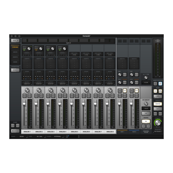
Page 39: Console Layout
Detailed explanations of all the Console control functions are similarly grouped and presented later in Console Reference. Window Title Bar Info View Channel Auxiliary Monitor Column Input Strips Return Strips Controls Console’s main window and controls layout Apollo Thunderbolt Software Manual Console Overview... - Page 40 To open another window, choose New Console Opening an additional Window from the drop menu under the UA icon in Console window on Mac the macOS Menu Bar at upper right of screen. Apollo Thunderbolt Software Manual Console Overview...
-
Page 41: Global Window Elements
(all unhidden channels) Column VIEW settings Auxiliary & Control Room Elements in this area columns appear depend on current VIEW here when SHOW settings button(s) are enabled Info Console elements that are always visible Apollo Thunderbolt Software Manual Console Overview... -
Page 42: Meter Bridge Overview
Stereo Signal Channel Input Meter Meter Present Signal (single) (dual) (green) (black) Meters Device Name Bank Bar Channels not in (optional via right-click) (gray) Current Bank (black) Non-Hidden Input Channels The Meter Bridge elements Apollo Thunderbolt Software Manual Console Overview... -
Page 43: Info Bar Overview
Sample Rate Apollo’s current sample rate is displayed here. Click this area to select a different sample rate from the drop menu when using Console without a DAW. Note: When using a DAW, the sample rate is managed within the DAW. -
Page 44: Current Bank Overview
(visible channels) within Bank Bar Conceptual illustration of the Current Bank. In this example, the Current Bank is analog channels 3 through 6. Sliding the Bank Bar brings different channels into the Current Bank view. Apollo Thunderbolt Software Manual Console Overview... -
Page 45: View Column Overview
Settings as it appears in Sends View The Settings switch opens the Accessing Console Settings, where various global functions are defined. Related functions are grouped within one of five available tabs in the window. Apollo Thunderbolt Software Manual Console Overview... - Page 46 Sends view. The channel input elements of each view are shown below. Complete details for all elements are described in Console Reference. Each View displays different elements in the input channel strips Apollo Thunderbolt Software Manual Console Overview...
-
Page 47: Monitor Column Overview
Monitor Level This is the master level control for Apollo’s monitor outputs. It performs the same function as the MONITOR knob on Apollo’s front panel. When the ring around the knob is RED, the monitor outputs are muted. Sessions Menu Clicking this switch opens the Session Manager popover window, where Console configuration files are managed. -
Page 48: Channel Strips Overview
(tip-sleeve) cable is connected to Apollo’s front panel Hi-Z input jack. Line Inputs (Apollo 16) Console’s 16 analog line inputs reflect the 16 channels of A/D conversion that are available in Apollo 16. Apollo 16 does not have preamp channels. Input Label... - Page 49 Apollo 8p, Apollo Twin Apollo Twin’s digital TOSLink input can accept ADAT or S/PDIF. Console’s inputs switch to reflect the digital input type currently in use (the digital input preference is set in the Console Settings window).
-
Page 50: Uad Plug-In Inserts Overview
Note: Audio on preamp channels is processed by the Unison in- sert (if active) before the channel inserts. The Unison insert is only available on Apollo preamp channels. However, Unison inserts are operated exactly the same way as The Unison Insert standard channel inserts. -
Page 51: Insert Effects Overview
(dry recording) or after the plug-in inserts (wet recording). Record With Effects When Insert Effects are record-enabled, Apollo’s hardware input signals are processed by Console’s UAD plug-in inserts before routing into the DAW. In this mode, the post-insert (wet) state of all Console inputs with Realtime UAD Processing is routed to the DAW inputs. -
Page 52: Popover Windows
Cue output assign Channel presets Rename/link channel inputs Console session presets Sends (Aux & Cue) Flex Route assign Insert assign I/O Matrix assign Plug-in presets I/O Matrix presets Talkback Sends (Apollo Twin MkII only) Apollo Thunderbolt Software Manual Console Overview... -
Page 53: Cues Overview
Cue Labels The cue labels vary per Apollo device model, as described below. Apollo, Apollo 8, Apollo 8p, Apollo 16 – The cues are labeled CUE 1, CUE 2, CUE 3, and CUE 4 respectively. Apollo Twin – With Apollo Twin, the two cues are labeled HP (headphone) and LINE 3/4 (line outputs 3 and 4) to reflect the available hardware outputs on the device. -
Page 54: Sends Overview
Sends Overview Apollo has a maximum of seven stereo mix buses (five with Apollo Twin) that are configured and adjusted within Console. The stereo buses are used for the monitor, auxiliary, and cue mixes. Each Apollo input has independent level, pan, and mute controls for each of the stereo mix buses. - Page 55 Click to open Sends popover Channel Send Level Indicators Channel Send Fader Indicators Channel Send Mute Indicators Send Bus Name & Colors (square above bus name) The Sends Display within each input channel strip in Overview view Apollo Thunderbolt Software Manual Console Overview...
- Page 56 Show All Sends Option All sends can be viewed simultaneously by holding the Option key (on computer keyboard) while clicking any SHOW switch in Sends View. All sends are visible when a SHOW switch is option-clicked Apollo Thunderbolt Software Manual Console Overview...
-
Page 57: Alt Monitoring Overview
Note: The ALT channel output assignments cannot be modified. Apollo, Apollo 8, Apollo 8p Apollo 16 – The ALT 1 monitor signal is routed to line outputs 1-2, and the ALT 2 monitor signal is routed to line outputs 3-4. -
Page 58: Console Sessions Overview
(blue) Session Files Selected Sub-Folder (blue) Current Session (gray) Other Sub-Folder (select to reveal contents) Function Buttons Load Load Save Create Load Existing Current Selected Session Session Session File Session The Sessions Manager popover Apollo Thunderbolt Software Manual Console Overview... -
Page 59: Console Settings Overview
Console Settings Overview Global parameters for Apollo and Console are configured in the Console Settings Window. Note: For complete details, see Console Settings. Console Settings Panels Controls within the Console Settings window are arranged according to related functionality. Each set of related controls are contained within a single panel. -
Page 60: I/O Matrix Overview
Core Audio / ASIO inputs/outputs, offering the ultimate in I/O routing flexibility when using any DAW. Custom I/O Names – The driver labels for Apollo’s I/O can be renamed so DAW inputs and outputs can use custom names. With the I/O Matrix, channel input and output selectors within a DAW can be (for example) “Electric Guitar”... -
Page 61: Multiple Undo/Redo
Undo/Redo until the cache is cleared. Both of these operations will clear the Undo/Redo cache: • Console is quit • A different Console session is loaded Important: Prior Undo/Redo operations cannot be performed after the Undo/Redo cache is cleared. Apollo Thunderbolt Software Manual Console Overview... -
Page 62: Keyboard Focus & Control
Typical focus indication. The PRESET column on the left has focus (orange outline) and can be navigated with the up/down arrow keys on the keyboard. The tab key alternates focus between the two columns. Apollo Thunderbolt Software Manual Console Overview... -
Page 63: Adjusting Console Controls
Mute/Solo All Toggle: Option-click a Mute or Solo switch to toggle the state on all channels. Drop Menus: Menus continue to display after a single click. The mouse button does not need to be held down to view the menu. Apollo Thunderbolt Software Manual Console Overview... -
Page 64: Keyboard Shortcuts
Command+, Ctrl+, Console Settings Open Console Settings window (comma) (comma) Revert the last executed function Undo Edit Command+z Ctrl+z (multiple Undo possible) Revert the last executed Undo Redo Edit Command+Shift+z Ctrl+Shift+z (multiple Redo possible) Apollo Thunderbolt Software Manual Console Overview... -
Page 65: Apollo Model Differences
Some Console features apply to Apollo rack models only (all models except Apollo Twin, which has a desktop form factor). In this manual, all specific references to Apollo Rack Models apply to Apollo, Apollo 8, Apollo 8p, Apollo 16, and Apollo 16 MkII models only. Apollo Model Notes Unless specifically noted otherwise, in this manual: •... -
Page 66: Console Reference
Current Bank (black) Non-Hidden Input Channels The Meter Bridge elements Input Channels The Meter Bridge represents all Apollo input channels. When an input channel is hidden with the Show/Hide Inputs function, that channel is not displayed in the Meter Bridge. - Page 67 Hover Scroll – Position the mouse over the Meter Bridge then scroll horizontally with the computer’s input device. Arrow keys – When the Bank Bar has keyboard focus, use the computer’s left/right arrow keys to navigate the Current Bank. Apollo Thunderbolt Software Manual Console Reference...
- Page 68 Show/Hide Offline Devices – Devices in the Hardware panel within the Console Settings window that are not currently connected are displayed in the Meter Bridge by default. To show/hide offline devices, choose this item from the menu. Identify – See Identify. Rename – See Device Name. Apollo Thunderbolt Software Manual Console Reference...
-
Page 69: View Column
View is active. View Option functions are performed using latched modifiers. See the Modifiers Overview for details on how to operate the View Option controls. See View Options for descriptions of the individual option functions. Apollo Thunderbolt Software Manual Console Reference... - Page 70 Tip: Click Clear Solo again to return all channels to their previous Solo states. Settings Switch The SETTINGS switch is located at the bottom of all View columns. It opens the Console Settings window, where many global functions are defined. For complete details, see Console Settings. Apollo Thunderbolt Software Manual Console Reference...
- Page 71 Tip: Modifier swipe shortcuts are the fastest way to perform the same function on multiple inserts. 2. Swipe Across 1. Click+Hold Click Swipe Swipe to rapidly perform the latched function on many inserts Apollo Thunderbolt Software Manual Console Reference...
-
Page 72: View Options
Tip: To disable individual plug-in processing without audio artifacts, use the power control within the plug-in interface instead, which keeps the plug-in loaded on the DSP. Apollo Thunderbolt Software Manual Console Reference... - Page 73 Copy Channel Strip When Copy is latched, click any input name modifier (at the bottom of the input strips) to copy all plug-ins in the channel inserts. The channel strip COPY modifier when latched Apollo Thunderbolt Software Manual Console Reference...
- Page 74 Console channel strip must run on a single SHARC processor. Therefore, it is possible to get a “DSP load limit exceeded” message on a channel even if the UAD gauges may indicate there is enough DSP available. Apollo Thunderbolt Software Manual Console Reference...
- Page 75 CUE BUS COUNT preference in Hardware panel within the Console Settings window. Apollo Twin – The two SHOW switches are labeled HP (headphone) and LINE 3-4 (line outputs 3 and 4) to reflect the available hardware outputs on this device.
- Page 76 Console window. Example screenshots of interaction between the send and monitor SHOW switches. By showing only one type of fader (Send or Monitor), the faders are taller, offering finer control resolution. Apollo Thunderbolt Software Manual Console Reference...
- Page 77 COPY TO Menu Right-clicking (or control-clicking) the main (silver) monitor faders presents the COPY TO menu. Selecting a destination performs the same function as the COPY TO modifier described above. COPY TO menu Apollo Thunderbolt Software Manual Console Reference...
-
Page 78: Info Bar
Display & Menu (Display only) The Info Bar Offline Hardware Display If the Apollo hardware unit(s) is not properly connected, the sample rate and clock source will display OFFLINE as shown below. Sample Rate and Clock when Apollo is offline Tempo Display This area displays the Console tempo in beats per minute (BPM). - Page 79 The Tempo Display is RED during this period. 4. After a new tempo value is established, the new tempo is used and the Tempo Display changes back to BLACK. Simply retransmit the MIDI data to apply further tempo updates. Apollo Thunderbolt Software Manual Console Reference...
-
Page 80: Sample Rate Display
Console when a DAW is active, digital artifacts could occur due to a sample rate mismatch. Apollo Twin Note: If the current digital input setting is S/PDIF and the sample rate is changed to a rate higher than 96 kHz, the clock source is changed to Internal and the S/PDIF inputs are no longer unavailable. - Page 81 The load for each gauge represents the average for all UAD devices in use. For example, if one Apollo QUAD unit is installed, the UAD DSP load is an average of the four SHARC DSP processors in the unit. If two QUAD units are installed, then the eight processors are averaged, and so on.
- Page 82 Static Loads Apollo uses UAD DSP and memory for its internal DSP mixer, therefore the meters will indicate loads (when the hardware is connected) even if UAD plug-ins are not inserted. The DSP gauge indicates the amount of digital signal processing resources that are being used by all UAD devices in the system.
-
Page 83: Channel Input Controls
Channel Strips Overview. Preamp Controls Note: The preamp controls do not apply to Apollo 16, which does not feature mic preamps. Console’s preamp controls correspond to the equivalent preamp controls on the Apollo front panel. Adjusting Apollo’s front panel will update Console (and vice versa); see Interactions Between Console and Apollo for details. - Page 84 Front Panel Channel Selection Indicator Dot Apollo’s channel selection can be changed using the front panel hardware. The small colored dot that appears next to the gain control (as shown at right, outlined in red) indicates the preamp channel that is currently selected with Apollo’s front panel.
- Page 85 Activate 48V only with compatible equipment such as phantom powered microphones. Incompatible equipment may be damaged by the applied voltage. Depending on the current configuration of the Apollo and Console, there may be a delay when changing the 48V state to minimize the clicks/pops that are inherent when engaging phantom power.
- Page 86 The availability and behavior of the reference level control depends on the hardware model, as described below. Apollo – The reference level for analog input channels 5 & 6 and 7 & 8 are linked in Apollo’s hardware. Therefore, the reference level in Console can only be switched according to these stereo pairs.
-
Page 87: Uad Plug-In Inserts
S/PDIF or AES/EBU inputs do not match Apollo’s internal sample rate. To enable realtime sample rate conversion on Apollo’s S/PDIF or AES/EBU inputs, click the SR Convert switch in Console’s associated channel strip. Click again to disable the feature. -
Page 88: Sends Popover
To access the Sends window, click the Sends display when Overview is active. Console Default Input Name Close Window Previous/Next Channel Bus Name & Color Send Mute Send Pan Send Level & Meter The Sends popover Apollo Thunderbolt Software Manual Console Reference... - Page 89 Sends Popover Window Descriptions Input Name – The name of the Apollo input is displayed as the window’s title. If the input name is customized in Console, the custom name is displayed here. Previous/Next Channel – These buttons switch the window to display the sends of adjacent channels.
-
Page 90: Flex Routing
Apollo’s inputs can be optionally routed to any available Apollo hardware output. A maximum of eight channel output route assignments are available for each connected Apollo rack model. This feature is available with Apollo rack models only (Flex Routing is unavailable with Apollo Twin). - Page 91 The number of currently available mono and stereo channel output routes is displayed in gray text at the bottom of the menu. The number is decremented with each assignment. Up to eight outputs can be assigned with Flex Routing for each connected Apollo rack model.
-
Page 92: Monitor Mix Controls
Monitor Mix Controls The monitor mix controls within the input channel strips are for adjusting the signals at Apollo’s Input monitor outputs. Note: Refer to the illustration at right for Input Input descriptions in this section. Solo Mute Input Pan This control adjusts the input’s position in the... -
Page 93: Input Mute
Ctrl-click) any channel fader to display the copy mix menu, then select a destination bus for the mix. Tip: This is the same function as the Sends COPY TO Modifier within the Sends View column. The Copy Mix menu Apollo Thunderbolt Software Manual Console Reference... - Page 94 The numerical labels represent digital signal levels. “0” represents 0 dBFS (digital full scale, the maximum level before undesirable A/D clipping). If the level at the Apollo input exceeds 0 dBFS, the meter’s clip indicator illuminates. If clipping occurs, reduce the preamp gain, the output level of the device feeding the input, or the output gain(s) of UAD plug-in processing in the inserts.
- Page 95 Stereo Link Switch The Rename/Link popover Input Label By default, the name of the Apollo hardware input is displayed beneath the channel’s fader and meter. The input labels can be customized for convenient input identification. Input labels showing several customized input names...
- Page 96 • A minimum of one input channel must be shown. • All input channels remain active even if they are hidden from view. • The Show Aux Returns switch is available to show/hide the aux return strips. Apollo Thunderbolt Software Manual Console Reference...
-
Page 97: Stereo Link
• Only the same type of inputs can be linked (for example, an analog input can only be linked to an analog input). • For preamp channels (Apollo & Apollo Twin), only the same input jacks can be linked (for example, a Mic input cannot be linked to a Line input). -
Page 98: Aux Returns
• Aux 2 is unavailable at sample rates of 176.4 kHz and 192 kHz. • The outputs of the aux buses have 32 samples of additional latency compared to the monitor outputs. This is necessary to maintain the lowest possible latency for the dry signals. Apollo Thunderbolt Software Manual Console Reference... - Page 99 Tip: Post-fader mode is typically used when configuring an effect send mix so the effect sends will interact with the main channel controls. Apollo Thunderbolt Software Manual Console Reference...
- Page 100 The clip and peak hold times can be adjusted in the Display panel within the Console Settings window. Tip: When recording into a DAW, it’s typically best to keep metering set to pre- fader so they accurately represent the signal level at the DAW inputs. Apollo Thunderbolt Software Manual Console Reference...
-
Page 101: Monitor Column
Monitor Meters The Monitor Meters display the levels of Apollo’s monitor mix bus. Levels displayed here mirror the state of the Monitor 1 – 2 LED meters on Apollo’s front panel. Global These meters are before the monitor output level control... - Page 102 These switches show and hide the visibility of the auxiliary return strips and/or the control room options strip. By default, these strips are not visible. The strips are visible when its SHOW switch is engaged (lit). The SHOW buttons disengaged (left) and engaged (right) Apollo Thunderbolt Software Manual Console Reference...
-
Page 103: Monitor Level
Monitor Level This is the master level control for Apollo’s monitor outputs. It performs the same function as the MONITOR hardware knob on Apollo’s front panel. Monitor Level Value The specific monitor output attenuation value in dB is displayed beneath the Monitor Level control. - Page 104 Console adjacent to the MONITOR text label, as circled in red at right. The dot provides a visual indication that the MONITOR level adjust function is active on the Apollo Twin hardware. When the dot is not Apollo Twin’s visible, adjusting Apollo Twin’s hardware level knob will not adjust the MONITOR dot monitor level.
-
Page 105: Cue Outputs Popover
(entire row) Cue Output Cue Source Cue Output Headphone Menu Select Mono Output Select The Cue Outputs popover with Apollo, Apollo 8, Apollo 8p Close CUE 1 Settings (entire row) CUE 2 Settings (entire row) Cue Output Cue Source Cue Output... - Page 106 Note: When CUE is the selected cue source, signals must be sent to that cue’s bus (via the cue sends) for the cue mix to be heard in the selected cue outputs. HP & LINE 3/4 (Apollo Twin) When set to HP, the headphone cue source is the dedicated HP mix, summed with all DAW outputs that are routed to the HP outputs (if applicable).
- Page 107 Cue Output Menu (Apollo rack models) This menu is used to optionally route the cue bus to Apollo’s available hardware outputs. To select a hardware output pair for the stereo cue, first click NONE to expose the drop menu, then select an available output pair from the menu.
-
Page 108: Control Room Column
ALT Level – Adjusts the output level of the main monitor mix when it is routed to a different pair of Apollo line outputs via the ALT monitoring function. The default value is 0 dB with an available range of ±30 dB. - Page 109 DIM when the button is released. Monitor Source Select These switches select the mix bus that is sent to Apollo’s monitor outputs. The source is selected when its switch is lit. When MIX is selected, the main monitor mix, summed with any DAW outputs assigned monitor outputs (if applicable), is routed to the monitor outputs.
-
Page 110: Console Sessions
Note: Without the .uadmix suffix, the session files will not be visible in the “Open” file dialogs or the Sessions menu, and they won’t be opened when they are double-clicked in the OS file system. Apollo Thunderbolt Software Manual Console Reference... - Page 111 Save – The current session is saved to disk and the session is loaded. If the session has never been saved to disk, this switch displays “Save As...” which opens the file save dialog. Apollo Thunderbolt Software Manual Console Reference...
-
Page 112: Sessions Manager Popover
Selected Session Session Session File Session The Sessions Manager popover Sessions Access To access the Sessions Manager window, single-click the area at the bottom of the Monitor Column. Click to open the Sessions Manager Apollo Thunderbolt Software Manual Console Reference... - Page 113 Tip: Session files can also be opened by double-clicking .uadmix files from within the operating system’s file system. Save Saves the current modified preset file in place. If the preset was not previously saved (if the file doesn’t exist), the Save As window appears. Apollo Thunderbolt Software Manual Console Reference...
- Page 114 Monitor Column. When the menu is displayed, clicking an item in the menu chooses that item. Refer to the diagram on the next page for Sessions Menu descriptions. Right-click in SES- SIONS area to display the Sessions Menu Apollo Thunderbolt Software Manual Console Reference...
- Page 115 Sub-folder names in the Sessions Menu are displayed in blue. Session files within the sub-folder are displayed beneath the blue sub-folder name (session files not within sub- folders appear at the top of the sessions list). Apollo Thunderbolt Software Manual Console Reference...
- Page 116 The previously-saved Console session’s filename is retained in the cached session, and a timestamp is prefixed so it can be easily distinguished from other sessions. The five most-recently cached sessions appear in the list. Apollo Thunderbolt Software Manual Console Reference...
-
Page 117: Window Title Bar
Console application is quit. Note: Console’s current settings are saved to disk when quit; when Console is subsequently launched, those settings are transferred to Apollo. Minimize – Clicking the “-” button reduces the window to the Dock (Mac) or Taskbar (Windows). -
Page 118: Application Menus
If the current session has been modified, a dialog appears allowing you to save it first. Open... Opens the operating system’s standard “Open File” dialog for loading existing session files from disk. Session files can also be opened by double-clicking .uadmix files from within the OS file system. Apollo Thunderbolt Software Manual Console Reference... -
Page 119: Edit Menu
All plug-ins can be categorically enabled from Console by selecting an item from the sub menu. Disable All All plug-ins can be categorically enabled from Console by selecting an item from the sub menu. Apollo Thunderbolt Software Manual Console Reference... - Page 120 This feature is typically used for adjusting Console sessions in multi-unit configurations when all Apollo devices are not currently connected. View Items Note: Items in this section perform the same function as clicking the View switches in the View column.
-
Page 121: Help Menu
Help Menu Documentation This item opens the local folder containing all Apollo product documentation files. Consult the documentation when you need specific operational information. After opening the folder, double-click a documentation file to open it. -
Page 122: Uad Plug-In Inserts
(click to switch) Active Plug-In (click to edit) Disabled Plug-In (gray background) Insert Slots 1 – 4 Offline Plug-In (red background) Empty Insert (click to assign) Record/Monitor Channel Insert Indicator Effects Switch The Channel Inserts Apollo Thunderbolt Software Manual UAD Plug-In Inserts... -
Page 123: Unison Insert
Note: Audio on preamp channels is processed by the Unison in- sert (if active) before the channel inserts. The Unison insert is only available on Apollo preamp channels. Click area outlined However, Unison inserts are operated exactly the same way as in red to insert a standard channel inserts. -
Page 124: Insert State Indicators
Remove Assign Power Assign – Opens the Assign popover window to replace the current plug-in with a different plug-in. Power – Disables/Enables plug-in processing and conserves UAD resources. The plug-in remains in the insert. Apollo Thunderbolt Software Manual UAD Plug-In Inserts... -
Page 125: Insert Options Menu
The single window, containing up to four plug-in GUIs, can be moved and arranged on screen as desired in a single motion. See Channel Strips for details. Apollo Thunderbolt Software Manual UAD Plug-In Inserts... -
Page 126: Channel Insert Effects
DAW input. UAD processing is heard in monitor outputs only. Important: UAD plug-in processing in Console’s Unison inserts is always routed to the DAW regardless of the current Insert Effects setting (Unison processing is always recorded). Apollo Thunderbolt Software Manual UAD Plug-In Inserts... -
Page 127: Plug-In Editor Window
Console Insert – The insert slot number (1 – 4) or Unison is displayed. Close – Closes the editor window. Minimize – Minimizes the editor window by placing it in the Dock (Mac) or Taskbar (Windows). Click the minimized window to restore it. Apollo Thunderbolt Software Manual UAD Plug-In Inserts... - Page 128 Click the switch to change the state. The plug-in is enabled when the switch is orange in color, and deactivated when the switch is gray. Deactivated plug-ins are indicated in the channel inserts by a light gray background. Apollo Thunderbolt Software Manual UAD Plug-In Inserts...
- Page 129 Manual – Opens the UAD Plug-Ins Manual for UA-developed plug-ins, or the manual provided by the developer for 3rd-party plug-ins. Web Info – Opens the default web browser and goes to the plug-in product page on the Universal Audio website (internet connection required). Apollo Thunderbolt Software Manual UAD Plug-In Inserts...
-
Page 130: Channel Strips
Channel Strip Enable switch within any plug-in in any channel insert. To disable Channel Strip mode and return to viewing the channel plug-ins individually, click the switch again. Click the Enable switch to activate Channel Strip view Apollo Thunderbolt Software Manual UAD Plug-In Inserts... - Page 131 OVERVIEW or INSERTS views (as shown at right). This meth- od can be used to load Channel Strip presets when plug-ins are not already loaded in the channel inserts. Click “INSERTS” to access Channel Strip presets Apollo Thunderbolt Software Manual UAD Plug-In Inserts...
-
Page 132: Presets Manager
Factory presets/folders are indicated by a lock icon at the left of a preset or folder icon. User presets/folders do not have the icon. Note: Not all UA Direct Developer (3rd-party) plug-ins include factory presets. Apollo Thunderbolt Software Manual UAD Plug-In Inserts... - Page 133 Each plug-in’s presets folder can contain one level of sub-folders for additional preset organization capability. The contents of sub-folders (if any) are displayed in the SUB- FOLDER column when a folder in the PRESET column is selected. Apollo Thunderbolt Software Manual UAD Plug-In Inserts...
- Page 134 The Channel Strip presets folder can contain one level of sub-folders for additional channel strip preset organization capability. The contents of sub-folders (if any) is displayed in the SUB-FOLDER column when a folder in the CHANNEL PRESET column is selected. Apollo Thunderbolt Software Manual UAD Plug-In Inserts...
-
Page 135: Presets Manager Popover
Click any preset in the PRESET column to instantly load it, or click a sub-folder (if any) to display presets within the sub-folder in the SUB-FOLDER column. If more presets or folders reside in the column than are currently within view, a scroll bar appears. Apollo Thunderbolt Software Manual UAD Plug-In Inserts... - Page 136 Delete – Deletes the selected preset file from disk and removes it from the presets list. A confirmation dialog appears before the file is deleted. Apollo Thunderbolt Software Manual UAD Plug-In Inserts...
-
Page 137: Save Preset Popover
Name Field – When creating a new preset or sub-folder, enter a unique name here. Cancel – Cancels the operation and returns to the main Presets Manager popover. Save – Creates the disk file or sub-folder. Apollo Thunderbolt Software Manual UAD Plug-In Inserts... -
Page 138: Console Settings
Console Settings Console Settings Overview Global parameters for Apollo and Console are configured in the Console Settings window. All Console Settings are detailed in this chapter. Note: On Windows PC systems, multi-unit functions described in this chapter are not yet available. Visit help.uaudio.com... -
Page 139: Changing Settings
Available Settings The parameters that are displayed in the Console Settings window can vary depending on the particular Apollo hardware model(s) that are currently connected to the system. Only settings that apply to the currently connected hardware are displayed. Any settings that are unique to a particular hardware model are noted in the descriptions. -
Page 140: Hardware Settings Panel
These settings are used by DAW applications when they are configured to use Apollo as the audio interface. Even when Console is not open, these settings are stored by the Apollo drivers for use by other host applications. -
Page 141: Sample Rate
Sample Rate This setting defines the sample rate that is used for Apollo A/D and D/A conversion and UAD Powered Plug-Ins processing. When using UAD Powered Plug-Ins, higher sample rates require more UAD DSP resources. Important: When the Clock Source parameter is set to use any external clock source, the sample rate must be manually set to match the sample rate of the external clock. - Page 142 This setting configures the S/PDIF outputs (Apollo, Apollo 8, Apollo 8p) or AES/EBU outputs (Apollo 16) to mirror the Monitor 1 & 2 outputs. This feature is typically used when connecting to the stereo inputs of other devices with digital inputs such as a speaker system, stereo recorder, or external D/A converter.
- Page 143 Count increases the number of cue mix buses (and associated cue sends and returns) available within Console and the DAW. Between two and four cue buses can be set. The default value is two with Apollo and four with Apollo 16. This setting is unavailable with Apollo Twin, which always features two cue mix buses (HP and Line 3/4).
- Page 144 Devices Column This column lists all Apollo devices in the system. It has four primary functions: 1. Selects current unit to see device-specific options 2. Designates the monitor unit in multi-unit setups 3. Indicates which unit(s) are currently online 4. Adds devices for offline configuration...
- Page 145 Device options as displayed for Apollo 8p (top) and Apollo Twin (bottom) Device Name Apollo’s default device name can be changed. The device name is displayed in the “Connecting to Apollo” window that appears briefly during system connection, in the I/O Matrix panel settings, and optionally in the Meter Bridge.
- Page 146 Console’s digital input channels. Apollo 8p and Apollo Twin supports S/PDIF digital input at sample rates up to 96 kHz. If the current setting is ADAT and the sample rate is higher than 96 kHz, when S/PDIF input is selected, the clock source is changed to Internal and the S/PDIF inputs are no longer unavailable.
- Page 147 This menu selects the digital output type (ADAT or S/PDIF) to be used by the TOSLINK optical connector and Console’s digital outputs channels. Apollo 8p supports S/PDIF digital output at sample rates up to 96 kHz. If the current setting is ADAT and the sample rate is higher than 96 kHz, when S/PDIF input is selected, the clock source is changed to Internal and the S/PDIF outputs are no longer unavailable.
-
Page 148: I/O Matrix Panel
Apollo outputs. I/O Matrix Rows Each row in the panel represents a single Apollo audio channel. The currently assigned input and output route for each channel is displayed within a single row. By clicking any assign switch, a different route can be mapped to the channel. -
Page 149: I/O Matrix Panel Elements
The main I/O Matrix panel elements Mode Menu This menu provides a quick method to return to Apollo’s default Core Audio / ASIO driver settings. When any settings within the I/O Matrix panel are not the default value, this menu displays “Custom.”... - Page 150 4 CUE mixes, or using up to 8 Virtual I/O channels). Note if older DAW sessions were saved using previous versions of Apollo’s driver and the I/O Matrix features are used upon reload, the Input/Output configuration tools in the DAW software may need to be modified.
- Page 151 I/O Presets window. Available functions at the bottom of the window can be performed on the selected I/O preset (a preset is selected when it is highlighted in blue). Apollo Thunderbolt Software Manual Console Settings...
- Page 152 DAW applications before changing the Channel Count settings. # Inputs – The number of active Apollo input channels used by Core Audio / ASIO is displayed here. Click the display to select a different input channel count from the menu.
- Page 153 Using Cascade to quickly assign multiple channels. In this example, ADAT 1 has been previously assigned to LINE 1 (left screenshot). With Cascade engaged (right screenshot), swiping the ADAT output across the LINE outputs quickly reassigns the LINE outputs to ADAT outputs. Apollo Thunderbolt Software Manual Console Settings...
- Page 154 Core Audio / ASIO channel names are shown, such as I/O channel assignments within a DAW. Apollo’s Core Audio / ASIO channel names can be customized by simply entering a different name in the Custom Name field. All custom name changes are instantly reflected in the application that displays channel names.
-
Page 155: Route Assign Popover
Route Assign Popover The Route Assign popover window is where Apollo I/O routes can be virtually re-mapped. To open the Route Assign window, click any assign switch. Important: Custom driver I/O routing changes the driver I/O complement. Quit all audio applications before changing driver I/O assignments. - Page 156 Apollo Hardware Channel The name of the Apollo hardware channel that is being re-assigned is displayed at the top of the window. Route Assign Columns The Device, Inputs, and Outputs columns are displayed in the Route Assign window.
-
Page 157: Display Panel
The Display panel Metering Pre-Fader When set to Pre-Fader, an input’s Channel Meter indicates the level at the Apollo input, regardless of the Channel Fader setting. With this setting, changing the fader level will not change the Channel Meter. Tip: When set to Pre-Fader, the Channel Meters mirror the signal level being recorded in the DAW. - Page 158 Meter Bridge. This feature is intended primarily for use with multi-unit systems. When the Meter Bridge contains the inputs for more than one Apollo unit, this feature groups the input channels by device name for easier input identification.
-
Page 159: Plug-Ins Panel
Circular (jump) – In Circular mode, the software knobs behave similar to physical rotary knobs. Values are changed by clicking on the knob then rotating in a circular direction. When the edge of the knob is clicked, the parameter value jumps to the mouse position. Apollo Thunderbolt Software Manual Console Settings... - Page 160 Tip: For detailed operational info for each plug-in, see the UAD Plug-Ins Manual. Buy Column Adds an unlicensed plug-in to the shopping cart at the UA online store. Confirm you are logged in to the desired account at uaudio.com when purchasing the plug-in. Apollo Thunderbolt Software Manual Console Settings...
-
Page 161: Midi Panel
Sets the MIDI data value to be used as the source for MIDI control. To set the data value, first click the field then enter a numerical value between 0 – 127, or send the value from the MIDI controller. Apollo Thunderbolt Software Manual Console Settings... - Page 162 MIDI Note Table When NOTE is used as the MIDI type, the table below can be used as a reference for MIDI note values. MIDI note numbers by note name and octave Apollo Thunderbolt Software Manual Console Settings...
-
Page 163: Console Recall Plug-In
DAW via the SYNC (synchronize) switch in the plug-in. It can also be used to view and adjust Apollo’s monitor output level, mono, and mute states without having to leave the DAW. SYNC The SYNC switch is not present within the Console application. When a DAW project... -
Page 164: Console Recall Controls
Console application does not need to be open when using the DAW with the Console Recall plug-in; Console settings are always captured by the Console Recall plug-in as long as the SYNC switch is engaged. Apollo Thunderbolt Software Manual Console Recall Plug-In... -
Page 165: How To Use Console Recall
When a DAW project is loaded that contains the Console Recall plug-in with SYNC enabled, the Session Name in the Console application displays “- Sync Session -” and the display is dimmed. Console session name when SYNC is enabled in DAW Apollo Thunderbolt Software Manual Console Recall Plug-In... - Page 166 Session State appears in the DAW, it’s best to just ignore it. Important: To ensure proper functionality when SYNC is enabled in Console Recall, do not create or edit DAW automations with the Session State parameter. Apollo Thunderbolt Software Manual Console Recall Plug-In...
-
Page 167: Unison
Unison is an audio processing breakthrough that starts right at the source, the input stage, allowing Apollo’s mic preamps to sound and behave like the world’s most sought- after tube and solid state preamps, guitar amps, and pedals — including their all- important impedance, gain stage “sweet spots,”... - Page 168 A/D conversion, the realism is faithful to the original target hardware preamp. • Tactile gain staging – Apollo’s front panel preamp knob can independently adjust all gain and level parameters available within the Unison plug-in via Gain Stage Mode.
-
Page 169: Activating Unison
Apollo, Apollo 8 – Preamp input channels 1 – 4 Apollo 8p – Preamp input channels 1 – 8 Apollo Twin – Preamp input channels 1 & 2 Apollo 16 – Unison is unavailable (Apollo 16 does not feature preamps) Unison Processing Important: Unison processing in Console’s Unison insert is always active on the... -
Page 170: Unique Behavior Of Unison Inserts
• The power switch within the Unison plug-in window is switched off • The Unison insert’s enable button is switched off • Apollo’s front panel preamp gain level indicator color reverts to green. Note: The above functions can be re-enabled after adequate UAD resources are made available. -
Page 171: Controlling Unison Plug-Ins With Apollo
Unison plug-ins may contain parameters that are unavailable for hardware control via Apollo. For example, the UA 610-B has EQ settings, but there are no EQ controls on Apollo’s hardware. To adjust these extra parameters, the Unison plug-in interface must be used. - Page 172 Front Panel Channel Selection Level Knob Switch In addition to the rotary control, Apollo’s front panel preamp level knob has a switch function when the knob is pressed. The function of this switch varies depending on the active mode (either Channel Select Mode or Gain Stage Mode), as described below.
- Page 173 Unison plug-in’s parameter that is being controlled. The color of Apollo’s front panel preamp gain level indicator (the LED ring around the knob) changes to reflect the gain stage being controlled, and the gain stage is also indicated by the matching color of the indicator dot within the Unison plug-in’s interface.
-
Page 174: Gain Stage Mode
Activating Gain Stage Mode To enable Apollo’s Gain Stage Mode when using a Unison plug-in: 1. In Console, confirm a Unison plug-in is inserted in the Unison insert of the Apollo preamp channel to be controlled. 2. On Apollo’s front panel, select the preamp channel to be controlled using the... - Page 175 2. The channel selection indicator on Apollo’s front panel stops flashing 3. If a gain stage other than the first gain stage was being controlled, Apollo’s gain level knob reverts to control of the first gain stage of the Unison plug-in, and the level indicator color reverts to orange.
- Page 176 Matching Gain Stage Indicators In Gain Stage Mode, Apollo’s preamp level indicator (the colored ring around the knob) matches the colored dot on the target gain parameter in the Unison plug-in’s interface, as shown below. The hardware and software controls are mirrored and the gain stage can be adjusted using either control.
-
Page 177: Unison Load/Save Behaviors
+48V phantom power. For example, if the PAD is ON in the Apollo preamp, when the Unison preset is loaded, the pad setting in the plug-in is enabled to prevent unexpected level increases. -
Page 178: Unison Operation Notes
Apollo’s stock preamps. For example, if the Unison plug-in has a 15 dB pad, then Apollo’s front panel PAD button value will use the Unison plug-in’s 15 dB value instead of Apollo’s stock 20 dB value. - Page 179 • If Apollo is disconnected from the host computer (standalone mode), the Unison plug-in can no longer be controlled from Apollo’s front panel. However, the signal continues to be processed by the Unison plug-in, using the values that were active when the connection was lost.
-
Page 180: Latency & Apollo
Driver Reporting Any system latency that is induced by Apollo’s I/O, Console, and/or UAD Powered Plug- Ins is reported by Apollo’s device drivers to the host audio software that is using the device. The host software uses this reported device latency for its automatic delay compensation (ADC) engine. - Page 181 1. Multiple Console inputs are used for a single source (such as a drum kit using multiple microphones), and 2. Any of those input channels contain upsampled UAD plug-ins. Tip: When IDC is not needed, disable Console IDC for the lowest possible input latency. Apollo Thunderbolt Software Manual Latency & Apollo...
- Page 182 Console will dynamically deliver the lowest possible monitoring latency. UAD-2 DSP Resources Console IDC uses a small percentage of Apollo’s UAD-2 DSP. To maximize DSP resource availability for UAD plug-ins, disable Console IDC if it is not needed.
-
Page 183: Latency Basics
Apollo’s Console DSP mixer is used for low-latency monitoring (cue mixing) of Apollo’s analog and digital inputs. Using Console to monitor Apollo’s inputs may or may not add to the inherent analog I/O round-trip latency, depending on how it is configured: Console without UAD plug-ins –... - Page 184 DAW latency can be a problem during recording when “software monitoring” via the DAW’s mixer, because the buffering delay is a distraction; an artist cannot hear their performance in realtime. DAW latency when recording with Apollo is mitigated by using the Console Mixer for live performance monitoring, where buffering latency does not apply.
- Page 185 UAD-2 DSP Latency When UAD Powered Plug-Ins are used within a DAW (not Console), I/O buffering is used to shuttle audio data back and forth between the UAD-2 inside Apollo and the DAW, which induces additional latency. This UAD-2 DSP “DAW processing method” latency is determined by the I/O Buffer Size setting.
-
Page 186: Apollo Twin Mkii Talkback
Console. This chapter explains the configuration and operation of all talkback features and functionality for Apollo Twin MkII. Note: Talkback features are available only when Apollo Twin MkII is connected via Thunderbolt. Talkback Functions Talkback is typically used by an operator in a studio’s control room to verbally... -
Page 187: Talkback Microphone
Realtime UAD Processing As with all Apollo inputs, the talkback mic input strip has four dedicated UAD plug-in inserts for Realtime UAD Processing for manipulating talkback mic sonics. For example, the mic’s high frequencies can be softened by filtering the top end with the included Precision Channel Strip plug-in. -
Page 188: Talkback Input Strip
Inserts Rec/Mon Indicator (click to switch) The talkback input channel strip is available in the Control Talkback Room module within Console whenever Apollo Twin MkII is Channel connected. Inserts To toggle visibility of the talkback strip, click the CTRL ROOM... - Page 189 This meter displays the input level for the talkback mic when the TALK button is engaged. By default, pre-fader levels are displayed. Post-fader levels can be displayed by changing the METERING setting in the Display panel within the Console Settings window. Apollo Thunderbolt Software Manual Apollo Twin MkII Talkback...
-
Page 190: Talkback Sends Popover
Tip: To increase the number of available CUE buses when multiple Apollos are connected in a multi-unit configuration, increase the CUE BUS COUNT value in the Hardware panel within the Console Settings window. Apollo Thunderbolt Software Manual Apollo Twin MkII Talkback... - Page 191 MIX Bus Meter – By default, pre-fader levels are displayed. Post-fader levels can be displayed by switching the METERING setting in the Display panel within the Console Settings window. CUE Bus Meters – Post-fader levels are always displayed. Apollo Thunderbolt Software Manual Apollo Twin MkII Talkback...
- Page 192 Tip: If a CUE color is gray, that cue’s SOURCE is set to MIX in the CUE OUTPUTS popover. Send Enable The cue talkback sends can be individually disabled. The send is enabled when its ON button is lit. By default, all sends are enabled. Apollo Thunderbolt Software Manual Apollo Twin MkII Talkback...
-
Page 193: Using Talkback
To activate the talkback mic, press a dedicated TALK button. The hardware or software buttons can be used. Apollo Twin MkII hardware – Press the top panel TALK button when the interface is in monitor mode (press the hardware MONITOR button to enter monitor mode). The green TALK indicator in the unit’s Options Display is lit when talkback is active. - Page 194 3. Record the mic as you would any other audio signal using the DAW’s operating procedures. Talkback Recording Notes: • The talkback mic is monophonic. Apollo Twin MkII’s TALKBACK 1 and TALKBACK 2 audio driver channels carry identical signals to facilitate DAWs that expect even pairs of inputs.
-
Page 195: Multi-Unit Cascading
In multi-unit systems, all Apollo devices are interconnected via a single Thunderbolt cable per unit, with a single Thunderbolt connection to the host computer. The host computer port, as well as any Thunderbolt devices on the bus (including Apollo), can be Thunderbolt 1 or Thunderbolt 2. -
Page 196: Multi-Unit Wiring
• In the wiring example diagram, the Apollo 8 in the center is designated as the monitor (master) unit. Connect speakers (including ALT speakers) to the monitor unit only. -
Page 197: Multi-Unit Operation
Thunderbolt devices may be connected and/or disconnected when the computer and/or devices are powered on (hot plugging). The order in which the Apollo units are connected and/or powered on is not critical. Apollo units are automatically detected a few moments after connection. - Page 198 Multi-Unit Monitor Control Monitor Knobs The monitor knob on the front panel of expander units (except Apollo Twin, as below), and its surrounding green LED indicator ring, are disabled. To adjust the monitor output level, the front panel monitor knob on the monitor unit (or the monitor level controls in Console or the Console Recall plug-in) must be used.
- Page 199 When two or more Apollo rack models are connected, Flex Routing can be used within each unit. Up to eight output routes can be assigned for each connected Apollo rack model. Note: Inputs can only be routed to the outputs of the same unit.
- Page 200 Show Device Names setting is particularly useful with multiple devices. The Meter Bridge with Apollo and Apollo 16, showing unique device colors Device Letter Each unit in the Devices list is designated with a sequential letter. These letters are used in the...
-
Page 201: Console Session Management
If a Console session was created and saved with Console 1 and the session is subsequently opened with a multi-unit Thunderbolt setup in Console 2 (UAD v8.0.1 or later Thunderbolt software), the previous Console 1 configuration is retained, with the exception noted below. -
Page 202: Device Drivers
Apollo’s audio drivers use the Core Audio (Mac) and ASIO (Windows) APIs. Apollo’s normal (non-DSP) audio interface features are simply seen as a Core Audio / ASIO device; therefore any Core Audio / ASIO compliant software can use Apollo for audio I/O. UAD Mixer Engine The Console application and Console Recall plug-in don’t actually communicate directly... -
Page 203: Driver I/O Tables
Tip: Each table is on a single page. For convenient reference with DAWs that don’t display driver I/O channels by name, print the sheet for your particular setup. Available Tables Click an Apollo model to jump directly to its table. Apollo Twin Default I/O (ADAT Mode) Apollo, Apollo 8 Default I/O... - Page 204 (for DAW inputs) (for Console inputs) †Apollo Twin MkII only Apollo Twin ADAT Input Channels and Sample Rates The ADAT digital input recognizes the following channels and sample rates: • Channels 1 – 8 at 44.1 kHz and 48 kHz •...
- Page 205 AUX2 R* TALKBACK 1† TALKBACK 2† *Software Outputs *Software Inputs (for DAW inputs) (for Console inputs) †Apollo Twin MkII only Note: Apollo Twin recognizes S/PDIF digital input at sample rates up to 96 kHz. Apollo Thunderbolt Software Manual Device Drivers...
- Page 206 Apollo, Apollo 8 Default I/O Apollo, Apollo 8 Driver Default I/O Table INPUTS OUTPUTS MIC/LINE/Hi-Z 1 MON L MIC/LINE/Hi-Z 2 MON R MIC/LINE 3 LINE 1 MIC/LINE 4 LINE 2 LINE 5 LINE 3 LINE 6 LINE 4 LINE 7...
- Page 207 Apollo, Apollo 8 Default I/O (4x Rates) Apollo, Apollo 8 Driver Default I/O Table 4x Sample Rates INPUTS OUTPUTS MIC/LINE/Hi-Z 1 MON L MIC/LINE/Hi-Z 2 MON R MIC/LINE 3 LINE 1 MIC/LINE 4 LINE 2 LINE 5 LINE 3 LINE 6...
- Page 208 Apollo 8p Default I/O (ADAT Mode) Apollo 8p Driver Default I/O Table Digital I/O Mode: ADAT INPUTS OUTPUTS MIC/LINE/Hi-Z 1 MON L MIC/LINE/Hi-Z 2 MON R MIC/LINE 3 LINE 1 MIC/LINE 4 LINE 2 MIC/LINE 5 LINE 3 MIC/LINE 6...
- Page 209 Apollo 8p Default I/O (4x Rates, ADAT Mode) Apollo 8p Driver Default I/O Table 4x Sample Rates, ADAT Mode INPUTS OUTPUTS MIC/LINE/Hi-Z 1 MON L MIC/LINE/Hi-Z 2 MON R MIC/LINE 3 LINE 1 MIC/LINE 4 LINE 2 MIC/LINE 5 LINE 3...
- Page 210 * Software Outputs *Software Inputs (for DAW inputs) (for Console inputs) † In multi-unit setups, available on monitor unit only Note: Apollo 8p recognizes S/PDIF digital I/O at sample rates up to 96 kHz. Apollo Thunderbolt Software Manual Device Drivers...
- Page 211 Apollo 16, Apollo 16 MkII Default I/O Apollo 16, Apollo 16 MkII Driver Default I/O Table INPUTS OUTPUTS LINE 1 MON L LINE 2 MON R LINE 3 LINE 1 LINE 4 LINE 2 LINE 5 LINE 3 LINE 6...
- Page 212 Apollo 16, Apollo 16 MkII Default I/O (4x Rates) Apollo 16, Apollo 16 MkII Driver Default I/O Table 4x Sample Rates INPUTS OUTPUTS LINE 1 MON L LINE 2 MON R LINE 3 LINE 1 LINE 4 LINE 2 LINE 5...
-
Page 213: Glossary
(such as a DAW). For example, a computer OS’s audio API enables audio hardware and audio software from different vendors to communicate with the OS and each other. Apollo Expanded Universal Audio’s name for connecting more than one Apollo device together via Thunderbolt in a multi-unit cascading setup for increased I/O. - Page 214 Bit Resolution Often used interchangeably with “bit depth,” this is a term used to describe the number of bits used in a digital recording. Apollo converts analog audio and transmits digital audio with a resolution of 24 bits (thus yielding a theoretical dynamic range of approximately 145 dB), the highest audio interface resolution in common use today.
- Page 215 External Clock A clock signal derived from an external source. (See “Clock”) FET Acronym for “Field Effect Transistor.” A type of transistor that relies on an electric field to control the shape, and hence the conductivity, of a “channel” in a semiconductor material. Apollo Thunderbolt Software Manual Glossary...
- Page 216 Firmware Software that is embedded in hardware. Flex Routing Apollo technology that enables its physical inputs to be routed to various physical outputs. Compare to Virtual I/O. FPGA Acronym for “Field Programmable Gate Array.” A type of integrated circuit that can be programmed after manufacturing (“in the field”) to perform specialized functions.
- Page 217 Universal Audio, that run exclusively on UAD DSP accelerator products. Quantization Noise A form of digital distortion caused by mathematical rounding-off errors in the analog to digital conversion process. Quantization noise can be reduced dramatically by dithering the digital signal. (See “Dither“) Apollo Thunderbolt Software Manual Glossary...
- Page 218 DAWs. Transient A relatively high volume pitchless sound impulse of extremely brief duration, such as a pop. Consonants in singing and speech, and the attacks of musical instruments (particularly percussive instruments), are examples of transients. Apollo Thunderbolt Software Manual Glossary...
- Page 219 Apollo’s mic preamp hardware to match the emulated preamp’s hardware design characteristics with bi-direction control. Virtual I/O Apollo audio inputs and outputs that exist in software but not in hardware. Virtual I/O is used to route digital audio channels between Console and other audio applications.
-
Page 220: Notices
Trademarks Universal Audio, the Universal Audio “diamond” logo, Apollo, Apollo Twin, Apollo 16, Unison technology, UAD, UAD Series, UAD-1, UAD-2, UAD-2 Satellite, Powered Plug- Ins, 1176LN, 1176SE, Teletronix, LA-2A, LA-3A, LA-610, LA-610MkII, 2-1176, 2-610,... -
Page 221: Technical Support
This website is independently owned and operated. • www.uadforum.com Contact UA Support Universal Audio provides free technical support to registered product owners. Support specialists are available to answer technical inquiries via email and telephone. • help.uaudio.com Apollo Thunderbolt Software Manual Technical Support... - Page 222 www.uaudio.com...
Need help?
Do you have a question about the Thunderbolt and is the answer not in the manual?
Questions and answers