
Summary of Contents for mensor CPG2500
- Page 1 Operating Instructions Precision Pressure Indicator CPG2500 Precision Pressure Indicator CPG2500 PN 0018908001F • 02/2017...
- Page 2 This Caution symbol indicates danger for the system and material if the respective safety precautions are not taken. Caution This Notice symbol does not indicate safety notices but information for a better understanding of the facts. Notice Operating Instructions - CPG2500...
-
Page 3: Table Of Contents
5.3 Mounting 5.4 Rear Panel 5.4.1 Pressure Connections 5.4.2 Pressure Port 5.4.3 Reference Port 5.5 Remote Communication Connections 5.6 Power Up 6. Local Operation and Setup 6.1 General Operation 6.1.1 Setup Applications 6.1.2 Display Screen Features Operating Instructions - CPG2500... - Page 4 6.4.5 Remote Application 6.4.5.1 Remote Command Set 6.4.5.2 Remote Communication Settings 6.4.6 Info Application 6.4.7 Leak Test Application 6.4.8 Troubleshooting Application 6.4.9 Service Application 6.4.10 Unlocked Service Application 7. Remote Operation 7.1 Command Set 7.2 IEEE-488 Operating Instructions - CPG2500...
- Page 5 7.5 Mensor Command Set 7.6 Command and Query Format 7.7 Command Set Definitions 7.8 Output Formats 7.9 CPG2500 Commands and Queries 7.9.1 Units Command Syntax for Measurement Units 7.9.2 CPG2500 Error Codes 7.9.3 SCPI Commands and Queries 7.9.4 SCPI Commands Error Messages and Error Codes 7.9.5 GPIB Capability Codes...
- Page 6 10.5.1 Service Application (unlocked) 10.6 Calibration Data 10.7 One Point Cal Application 10.8 Two Point Cal Application 10.9 Linearization 10.10 Head Pressure 11. Appendix 11.1 Conversion Factors, PSI 11.2 Conversion Factors, Millitorr 11.3 Conversion Factors, Pascal Operating Instructions - CPG2500...
-
Page 7: General Information
Mensor, this warranty does not apply. The judgment of Mensor will be final as to all matters con- cerning condition of the product, the cause and nature of a defect, and the necessity or manner of repair. -
Page 8: Trademarks And Copyrights
Notice Mensor and its suppliers shall not be held to any liability for any damages suffered or incurred by the end user (including, but not limited to, general, special, consequential or incidental damages including dam- ages for loss of business profits, business interruption, loss of business information and the like), arising from or in connection with the delivery, use or performance of the software program. -
Page 9: Safety Notices
Extreme care must be taken with pressure connections when using hazardous or toxic media. Repairs must only be performed by authorized service personnel. Additional safety notices are found throughout this manual. Notice Operating Instructions - CPG2500... -
Page 10: Warnings And Caution Notices
CAUTION: ESD PROTECTION REQUIRED. The proper use of grounded work surfaces and personal wrist straps are required when coming into contact with exposed circuits (printed circuit boards) to prevent static discharge to sensitive electronic components. Additional Warning and Caution notices are found throughout this manual. Operating Instructions - CPG2500... -
Page 11: General Description
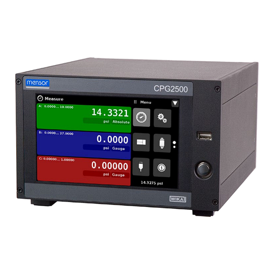
The CPG2500 Precision Pressure Indicator is a multi-channel pressure indicator designed to test and calibrate a variety of pressure devices in either absolute or gauge pressure modes. The CPG2500 can have two independent internal transducers, an optional barometric reference and an external remote pressure transducer. -
Page 12: Turning On
CPG2500 Turning On You can confirm that your CPG2500 is operational right now. Apply power to the power connector on the rear of the instrument with the included power adapter, remove any plastic plugs from the rear panel pressure ports, and press the power switch to ON. The system will go through an initialization process, which takes about 45 seconds, and then a display will appear similar to the screen shown below. -
Page 13: Display
The chassis assembly is the housing for the system and the removable transducers. The system has no user-serviceable parts, and therefore the chassis should not be opened except by qualified repair per- sonnel at Mensor or certified service locations for any reason except to change the removable transduc- ers. - Page 14 Precision Pressure Indicator CPG2500 NOTES Operating Instructions - CPG2500...
-
Page 15: Specifications
ISO Guide to the Expression of Uncertainty in Measurement (GUM). The calibration program at Mensor is accredited by the American Association of Laboratory Accreditation (A2LA) as complying with both the ISO/IEC 17025:2005 and the ANSI/NCSL Z540-1-1994 standards. If there is an exception to the requirements and recommendations of Z540 during a calibration the excep- tion is noted on the individual calibration certificate. - Page 16 0.008 % IS-50 accuracy: Between 0 ... 50 % of the full scale, the accuracy is 0.008% of half of the full scale value and between 50 ... 100 % of the full scale, the accuracy is 0.008 % of reading. Operating Instructions - CPG2500...
- Page 17 IEEE 488, RS-232, USB and Ethernet Command sets Mensor, WIKA SCPI CE conformity and certificates CE compliance EN61326-1:2013 electromagnetic compliance EN61010-1:2010 safety/CB scheme Calibration Calibration certificate per ISO/IEC 17025:2005. Accreditation is by the American Association for Laboratory Accreditation (A2LA). Operating Instructions - CPG2500...
-
Page 18: Installation
Report any apparent damage to the carrier immediately. In addition to this manual you should have: • CPG2500 Precision Pressure Indicator; • Power Supply; • Fitting adapters ordered; • Any accessories ordered;... -
Page 19: Dimensions (Inches)
Dual mount - Front view Rear Panel Baro ref port IEEE-488 (baro ref option) Remote Transducer connection RS-232 USB (device) USB (host) Ethernet port Measure port Measure port Power Channel A Channel B (7/16-20 UNF) (7/16-20 UNF) Operating Instructions - CPG2500... -
Page 20: Mounting
Rear Panel Two slots are available on the rear of the CPG2500. These slots can be filled with a removable transducer or a remote transducer interface connection. Gauge Transducers will have a reference and a pressure port. Absolute transducers will have a plug in the reference port. In the upper right corner is a hose barb fitting which is connected to the baro ref if installed. -
Page 21: Pressure Connections
MS16142 and SAE J514 table 14. Connected adaptors require a tube fitting boss seal with an o-ring per MS33656. Mensor can provide a variety of adapter fittings (see Section 8 Op- tions) with the instrument. Do not use sealant on fittings sealed with an o-ring. The integrity of each seal is particularly important since even microscopic leaks can cause errors in pressure measurements. -
Page 22: Local Operation And Setup
Color coding persists throughout all channel-specific screens. A zero or tare button and auxiliary displays (auxiliary units, rate and peak) will appear in the Measure App if activated. All of the CPG2500 screen features are described in more detail throughout this manual. -
Page 23: Initial Setup
Section 6.3.1 and 6.3.2 are provided first so that the operator can initially check the information screen to verify the installed components and to change the language if needed. 6.2.1 Contact and Version Information Application Press this application button to display Mensor contact, installed sensor, instrument and software version information. Figure 6.2.1 - Information 6.2.2 Language Selection... -
Page 24: Application Selection And Parameter Inputs
] above the input area. The purpose and use of each selection and menu is intuitively apparent and will become second nature with minimal expo- sure to the menu structure. Menu Button Input Title App Title Page Down Operating Instructions - CPG2500... -
Page 25: Applications
Any unit of measure can be selected for any channel. If a barometric reference is installed, the Mode button, described below, will toggle from Gauge to Absolute mode when pressed. Units Button Figure 6.4.1-A Basic Measure App Mode Button Figure 6.4.1-B - Units Change Operating Instructions - CPG2500... -
Page 26: Pressure Mode / Emulation Mode
“Alternate Units”, “Peak” and “Rate”. Calibration functions are either a “Zero” button or a “Tare” button. These auxiliary features will appear in the Measure App when selected from the Transducer App (section 6.4.4.4). Figure 6.4.1.2 - Three channel Measure App with auxiliary displays Operating Instructions - CPG2500... -
Page 27: Zero Button
Figure 6.4.1.3 - Zero Button, Gauge - Absolute The background color of the zero button will momentarily change to a lighter color as the zero calibration is performed then will revert back to a darker color when complete. Operating Instructions - CPG2500... -
Page 28: Tare Button
Pressing the tare button again will deactivate the tare and change the pressure indication back to the reading corresponding to the calibrated output of the transducer. An active tare will revert to a deacti- vated state after a power cycle. Operating Instructions - CPG2500... -
Page 29: Settings Application
The Language parameter provides a selection of different languages. Once a language is chosen all words within all menus will appear in the chosen language and the radix character (decimal mark) will change from a dot (.) to a comma (,) depending on the language chosen. Figure 6.4.2.1 - Languages Operating Instructions - CPG2500... -
Page 30: Brightness
After the setting is made and your finger is removed from the screen the menu will revert back to the basic settings menu. Figure 6.4.2.2 - Brightness 6.4.2.3 Volume The Volume setting provides a way to turn on or off the touch screen audio feedback. Figure 6.4.2.3 - Volume Operating Instructions - CPG2500... -
Page 31: User Base Units / Base Units Multiplier
Any of these units can be chosen from this list for the barometric readout that can be seen on the bottom right of the Measure App. Figure 6.4.2.5 - Barometer units Operating Instructions - CPG2500... -
Page 32: Configuration
To reload a saved configuration at a later time, go to Settings-Config- uration and press the numbered configuration button corresponding to the saved configuration and then press the “Load” button. Figure 6.4.2.6 - Configuration The instrument default configuration can be activated simply by pressing the “Default” Button. Operating Instructions - CPG2500... -
Page 33: Frames Application
6.4.3.1 Frame Format The Frame format button sets the display in the Measure Application to Single Frame, Dual Frame or Triple Frame. Figure 6.4.3.1 shows the available selections for the Frame Format parameter. Figure 6.4.3.1 - Frame Format Operating Instructions - CPG2500... -
Page 34: Frames Channel
Channel “B” in the middle and the “Delta” channel on the bottom. The barometer reading (if installed) will appear as a selectable channel and will always be in the bottom right under the application menu. Figure 6.4.3.2-A - Example channel frame settings Operating Instructions - CPG2500... -
Page 35: Transducer Application
To set the transducer parameters, the transducer channel must be selected. Transducer parameters are identical for all channels but can be set differently in each channel. Figure 6.4.4.1 shows two displays where channel “A” and “B” have been selected. Figure 6.4.4.1 - Transducer Channel Selection Operating Instructions - CPG2500... -
Page 36: Transducer Delta Emulation
Turn off the Filter by selecting “Off”, select varying degrees of filtering for the current units by selecting “Low”, “Normal” or “High”. Figure 6.4.4.3 - Transducer Filter Operating Instructions - CPG2500... -
Page 37: Transducer Resolution
6.4.4.4 Transducer Resolution The resolution of each transducer channel can be set in the Transducer Application using the resolution parameter. The resolution can be set to 4, 5, 6 or 7 digits. Figure 6.4.4.4 - Transducer Resolution Operating Instructions - CPG2500... -
Page 38: Auxiliary Displays
3 set for units, peak and rate respectively. Auxiliary displays will appear in the Measure App as seen in Figure 6.4.4.5-B. Figure 6.4.4.5-A - Transducer channel aux displays set to Units, Peak and Rate Figure 6.4.4.5-B - Auxiliary displays as seen in the Measure App Operating Instructions - CPG2500... -
Page 39: Cal Function
App. The Tare button and the Zero Button cannot appear on the screen at the same time, in the same channel. See section 6.4.1.3 and 6.4.1.4 for operation of the Zero and Tare buttons in the Measure App (main screen). Figure 6.4.4.6 - Cal Function Operating Instructions - CPG2500... -
Page 40: Remote Application
Figure 6.4.5 - Remote Application 6.4.5.1 Remote Command Set The remote command set parameter provides a choice of the Mensor command set or the WIKA SCPI command set. Both sets of commands are listed in Section 7, Remote Operation. Figure 6.4.5.1 - Remote Command Set... -
Page 41: Remote Communication Settings
If a DHCP server is not found, an error will be indicated. If DHCP is enabled, the IP address, Netmask and Gateway are greyed out and locked, these are controlled by the DHCP server. Figure 6.4.5.2 - Remote Communication Settings Operating Instructions - CPG2500... -
Page 42: Info Application
CPG2500 6.4.6 Info Application The Info application displays information about the instrument, including: • Mensor address, and email • Model number, serial number and operating software version. • Sensor model number, serial number, range, software version Figure 6.4.6 - Info Application... -
Page 43: Leak Test Application
“passed” test. See Figure 6.4.7-A for examples of a failed and a passed test. Figure 6.4.7 - Leak Test Figure 6.4.7-A - Leak test fail (left) & Leak test pass (right) Operating Instructions - CPG2500... -
Page 44: Troubleshooting Application
] will appear in all screens (Figure 6.4.8- A) of the instrument. Pressing this error button from any screen will open the Troubleshoot application where the error can be viewed. Figure 6.4.8-A - Error indication Figure 6.4.8-B - Troubleshoot error and remote Operating Instructions - CPG2500... -
Page 45: Service Application
Default password is 123456. Enter 123456 and press the check mark [ ] to unlock the Service Application. Figure 6.4.9-B - Service Application (Enter Password) Note: The default Password is 123456. After entering this for the first time, the password can be changed. Operating Instructions - CPG2500... -
Page 46: Unlocked Service Application
The Unlocked Service Application is the access point to all calibration screens described in Section 10 of this manual. Note: Recommended calibration setup and explanation of calibration screen applica- tions is covered in Section 10 of this manual. Operating Instructions - CPG2500... - Page 47 Precision Pressure Indicator CPG2500 NOTES Operating Instructions - CPG2500...
-
Page 48: Remote Operation
Clear status and error queue *ESE Enable status event *ESE? Returns enable status even value *ESR Event status register *ESR? Returns even status register value *SRE Service request enable *SRE? Returns service request enable value *STB? Returns status byte Operating Instructions - CPG2500... -
Page 49: Ethernet
CAUTION: Please consult your computer resources department prior to connect- ing this instrument to your network to verify there are no conflicts with existing IP addresses. Caution The Ethernet communication port allows the CPG2500 to communicate with computers using 10/100Based-T specifications. Before using Ethernet communication, four parameters must be set up: IP, Netmask, Gateway, and Port. Operating Instructions - CPG2500... -
Page 50: Serial
1 stop bit, no parity, and no echo. If echo is ON, the CPG2500 will immediately echo back characters sent over the serial port. The Serial function allows the user to set the RS-232 serial port settings by selecting from the choices provided: •... -
Page 51: Mensor Command Set
CPG2500 Mensor Command Set This Mensor command set is the default on the CPG2500. For queries (ending with a ?), the Data column represents the response of the CPG2500. All response strings begin with a space character or an “E”... -
Page 52: Output Formats
Table 7.9 lists all of the current CPG2500 commands and queries. Channel specific commands are sent to only the active channel. See ‘CHAN’ command. Notice Optional emulation modes are available in which a CPG2500 can emulate remote functions of different brands of pressure gauges. Please contact Mensor for more details. Table 7.9 - CPG2500 Commands and Queries Command... - Page 53 Filter OFF, LOW, NORMAL, HIGH Sets the reading filter 0, 80%, 92%, Filter? <sp> (filter)<cr><lf> Returns the reading filter Gasdensity Value in lb/cuft, or “NITROGEN” or Sets the head pressure gas density in “DRYAIR” lb/cuft Operating Instructions - CPG2500...
- Page 54 Height? <sp>+n.nnnnnE+nn<cr><lf> Gets the head pressure height in inches <sp>MENSOR, ssssss is the serial number,v.v.vv is CPG2500, ssssss, the CPG2500 software version v.v.vv<cr><lf> nnn.nnn.nnn.nnn Sets the IP address of the instrument <sp>nnn.nnn.nnn.nnn<cr><lf> Returns the IP address of the instru- ment...
- Page 55 ?, clears previous value, must be > 50% FS and has a 1% limit. CALDIS- ABLE must be OFF/NO. Span? <sp>XXXXXXX<cr><lf> Returns span scale factor for active transducer Sparity Even, ODD, NONE Sets the serial parity Sparity? <sp>CCCC<cr><lf> Returns the serial parity Operating Instructions - CPG2500...
- Page 56 Except for the engineering units selection, the numeric suffix selects the applicable channel/sensor: 1 = Channel A 2 = Channel B 3 = Channel C 4 = Channel D 5 = baro (if installed) This numeric suffix always defaults to 1 and is designated by [C] (channel) Operating Instructions - CPG2500...
-
Page 57: Units Command Syntax For Measurement Units
@ 0°C Metric tons per square inch Imperial hectapascals Metric megapascals Metric millimeters of water @ 20°C MMH2O Metric centimeters of water @ 20C CMH2O Metric meters of water @ 20°C MH2O Metric Operating Instructions - CPG2500... -
Page 58: Cpg2500 Error Codes
Precision Pressure Indicator CPG2500 7.9.2 CPG2500 Error Codes Code Serial Poll Byte Description Error String Returned No errors NO ERRORS Parameter error EGPIB PARAMETER ERROR: String that was sent Syntax error EGPIB SYNTAX ERROR: String that was sent 7.9.3 SCPI Commands and Queries... - Page 59 3 psi 4 atm 5 kp/cm2 6 lbf/ft2 7 kPa 8 cmH2O(4°C) 9 inH2O(4°C) 10 inH2O(60°F) 11 ftH2O(4°C) 12 µmHg(0°C) 13 mmHg(0°C) 14 cmHg(4°C) 15 inHg(0°C) 16 inHg(60°F) 17 - - 18 user 19 user 20 user Operating Instructions - CPG2500...
-
Page 60: Scpi Commands Error Messages And Error Codes
Group Execute Trigger: When this message is received, the CPG2500 will save the current read- ings until the next time it is addressed as a talker. Go To Local: A GTL message will cause the CPG2500 to return to local operation and unlock the keyboard. - Page 61 Precision Pressure Indicator CPG2500 NOTES Operating Instructions - CPG2500...
-
Page 62: Options
• Remote calibrations sleds (transducers, Barometric reference) Barometer The CPG2500 can be ordered as a single range Barometer. It is a very stable, absolute pressure sen- sor, used to accurately measure local atmospheric pressure. The only significant difference between a barometer and a regular transducer is that the transducer in a Barometer is calibrated from 8 to 17 psia and has an accuracy of 0.01% of reading. -
Page 63: Emulation Mode Accuracy
The CPT6100 and CPT6180 are stand alone Digital Pressure Transducers that can be purchased separately and connected to the remote transducer port on the back of the CPG2500. They can also be connected to an external sensor package (D-Sub) (See Section 8.5 below) that has been installed in the place of a removable transducer. -
Page 64: Analog Output
A cable / power supply and software are available to remotely calibrate the internal transducers outside of the CPG2500. In both cases a PC with a serial connection is required. Both kits are supplied with an instruction manual. -
Page 65: Remote Calibration Kit For Internal Transducers
Figure 8.9.1 - Remote Calibration Kit for Internal Transducer 8.9.2 Barometric Reference Calibration Sled The CPG2500 Calibration Sled Kit is available to provide a way to calibrate the barometric reference re- motely. Calibration of the Barometric Reference can be performed remotely using the Cal sled, a PC and the software provided. -
Page 66: External Calibration Procedures
CAUTION: ESD protection is required when performing this operation. Thumb Screw Figure 8.9.3.2 - Internal Barometric Reference Operating Instructions - CPG2500... - Page 67 Precision Pressure Indicator CPG2500 NOTES Operating Instructions - CPG2500...
-
Page 68: Maintenance
We use this knowledge in our continuing effort to design better and more robust instruments. Spare Parts Table 9.2 lists the spare parts for the CPG2500 that can be ordered from Mensor. Table 9.2 - Spare Parts List Part Description... - Page 69 Precision Pressure Indicator CPG2500 NOTES Operating Instructions - CPG2500...
-
Page 70: Calibration
The recommended calibration medium is dry nitrogen or clean dry instrument air. Hydraulic media can be used above 15 psi. A height variation between the standard and the CPG2500 can cause significant errors. A calculation should be made to compensate for this difference. -
Page 71: Setup
600 millitorr absolute is recommended. Unnecessary for Gauge Calibration Variable Leak Vacuum Vacuum Pump Metering Valve Shut O Supply Volume Controller PC for Remote Calibration Vent Pressure Standard Vacuum Gauge Figure 10.4 - Calibration Setup Operating Instructions - CPG2500... -
Page 72: Service Application
Press the Enter button to show the numeric keypad to enter a password. This will unlock other applica- tions. The Default password is 123456. Enter 123456 and press the check mark [ ] to unlock the Service Application. Figure 10.5-B - Service Application (Enter Password) Note: The default Password is 123456. After entering this for the first time, the password can be changed. Operating Instructions - CPG2500... -
Page 73: Service Application (Unlocked)
Check Mark [ Note: Please make note of a password change and save the new password in a secure location. The Unlocked Service Application is the access point to all calibration screens described below. Operating Instructions - CPG2500... -
Page 74: Calibration Data
(known true pressure) using the keypad. If you want to save the value in the sensor, press Save. Notice the reference symbol [ this is a reference indication giving a constant reference point for the level of the internal sensor. Figure 10.7 - One Point Cal Application Operating Instructions - CPG2500... -
Page 75: Two Point Cal Application
“High Reading” by pressing the High Reading button and entering the number followed by the check mark [ ]. Record the “true pressure” obtained from the reference standard and enter it as the “High Reference” value in the same manner. Operating Instructions - CPG2500... -
Page 76: Linearization
These values can be changed to reflect the values generated by the standard and the corresponding readings taken from the CPG2500. Each value from the standard can be entered under the reference column, corresponding Upscale and Downscale readings from the instrument can be entered in the “Upscale”... - Page 77 Note: After calibration is complete, return to the Calibration Data Application (Section 10.6) to record the certificate number, calibration interval and the date of calibration. Restoration to factory calibration can also be completed in this application. Operating Instructions - CPG2500...
-
Page 78: Head Pressure
The four parameters are used to calculate the pressure that is a result of the different elevations. It should not be used when calibrating CPG2500 transducers. The Head height should be set at zero before cali- brating the transducers of the CPG2500. - Page 79 Figure 10.10-B shows the Head Pressure hydraulic screen. The height, media density, media tempera- ture and local gravity can be entered here based on the specific setup of the system Figure 10.10-B - Head Pressure, Hydraulic Operating Instructions - CPG2500...
-
Page 80: Appendix
@ 20°C mmH2O 20°C centimeter of water @ 20°C cmH2O 20°C meters of water @ 20°C MH2O 20°C User Units 1 User defined User Units 2 User defined Operating Instructions - CPG2500... -
Page 81: Conversion Factors, Psi
MSW 0°C 3.5% salinity 0.6838528 1.462303 0.0625 0.006944444 0.072 13.88889 (PSI / RANGE) x 100 (% FS x RANGE) / 100 µHg 0°C 51715.08 0.00001933672 0.0005 2000 68.94757 0.01450377 0.006894757 145.0377 mmH2O 20°C 704.336 0.001419777 cmH2O 20°C 70.4336 0.01419777 Operating Instructions - CPG2500... -
Page 82: Conversion Factors, Millitorr
0.750063626 gm/cm2 0.001359506 735.561166 kg/cm2 0.000001359506 735561.166 MSW 0°C 3.5% salinity 0.00001322347 75623.11663 0.0003093875 3232.1992 0.002784488 359.132477 0.000001392244 718265.0575 µHg 0°C 1.000000000 0.00000000966836 103430160.00 0.001333220 750.0636259 0.0000001333220 7500636.259 mmH2O 20°C 0.01361955 73.42388114 cmH2O 20°C 0.001361955 734.2388114 Operating Instructions - CPG2500... -
Page 83: Conversion Factors, Pascal
1.00000E+00 Dy/cm2 1.00000E+01 1.00000E-01 gm/cm2 1.019716E-02 9.806647E+01 kg/cm2 1.019716E-05 9.806647E+04 MSW 0°C 3.5% sal 9.918444E-05 1.008222E+04 2.320603E-03 4.309223E+02 2.088543E-02 4.788025E+01 1.044271E-05 9.576052E+04 µHg 0°C 7.500636E+00 1.333220E-01 7.251885E-08 1.378951E+07 1.00000E-02 1.00000E+02 1.00000E-06 1.00000E+06 mmH2O 20°C 1.021553E-01 9.789017E+00 Operating Instructions - CPG2500... - Page 84 Precision Pressure Indicator CPG2500 cmH2O 20°C 1.021553E-02 9.789017E+01 MH2O 20°C 1.021553E-04 9.789017E+03 Operating Instructions - CPG2500...
- Page 85 Precision Pressure Indicator CPG2500 NOTES Operating Instructions - CPG2500...
- Page 86 201 Barnes Drive San Marcos, Texas 78666 Phone: 512.396.4200 Web site: www.mensor.com Fax: 512.396.1820 E-mail: sales@mensor.com Precision Pressure Indicator CPG2500 PN 0018908001F • 02/2017 WIKA Alexander Wiegand SE & Co. KG Alexander-Wiegand-Straße 30 D-63911 Klingenberg / Germany Tel: (+49) 93 72/132-9986 Web site: www.wika.de...
Need help?
Do you have a question about the CPG2500 and is the answer not in the manual?
Questions and answers