Philips MCM233 Service Manual
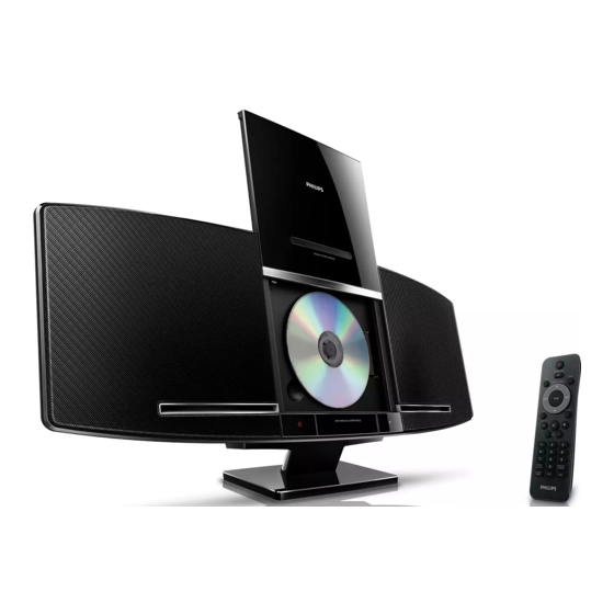
Sleek micro music system
Hide thumbs
Also See for MCM233:
- Quick start manual (4 pages) ,
- User manual (20 pages) ,
- Guía de inicio rápido (4 pages)
Advertisement
Sleek micro music system
CONTENTS
Technical specification ..................................................................1-2
Service measurement setup..........................................................1-3
Service aids .................................................................................1-4
Instructions on CD playability ...............................................2-1.. 2-2
Block diagram................................................................................3-1
Wiring diagram ..............................................................................3-2
Main board
Circuit diagram ..................................................................4-1..4-2
Layout diagram..................................................................4-3..4-4
Key board
Circuit diagram .........................................................................5-1
Layout diagram.........................................................................5-2
LCD board
Circuit diagram .........................................................................6-1
Layout diagram.........................................................................6-2
Headphone board
Circuit diagram .........................................................................7-1
Layout diagram.........................................................................7-2
Exploded view diagram .................................................................8-1
Revision list....................................................................................9-1
©
Copyright 2010 Philips Consumer Electronics B.V. Eindhoven, The Netherlands
All rights reserved. No part of this publication may be reproduced, stored in a retrieval
system or transmitted, in any form or by any means, electronic, mechanical, photocopying,
or otherwise without the prior permission of Philips.
Published by LX 1042 Service Audio
Version 1.2
Subject to modification
MCM233
-/12/55/79/78/98
3141 785 34892
Advertisement
Table of Contents

Related Manuals for Philips MCM233


Summary of Contents for Philips MCM233
-
Page 1: Table Of Contents
Revision list..................9-1 © Copyright 2010 Philips Consumer Electronics B.V. Eindhoven, The Netherlands All rights reserved. No part of this publication may be reproduced, stored in a retrieval system or transmitted, in any form or by any means, electronic, mechanical, photocopying, or otherwise without the prior permission of Philips. -
Page 2: Technical Specification
Tuner Tuning range FM: 87.5 - 108 MH z Tuning grid 50 KH z Number of presets VERSION VARIATION Type /Versions: MCM233 Service policy Board in used: LCD BOARD KEY BOARD POWER KEY BOARD OPEN/CLOSE BOARD REMOTE INCEPT BOARD RADIO BOARD... - Page 3 MEASUREMENT SETUP Tuner FM Bandpass LF Voltmeter 250Hz-15kHz e.g. PM2534 e.g. 7122 707 48001 RF Generator e.g. PM5326 S/N and distortion meter e.g. Sound Technology ST1700B Use a bandpass filter to eliminate hum (50Hz, 100Hz) and disturbance from the pilottone (19kHz, 38kHz). Tuner AM (MW,LW) Bandpass LF Voltmeter...
-
Page 4: Service Aids
SERVICE AIDS WARNING All ICs and many other semi-conductors are susceptible to electrostatic discharges (ESD). Careless handling during repair can reduce life drastically. When repairing, make sure that you are connected with the same potential as the mass of the set via a wrist wrap with resistance. Keep components and tools also at this potential. -
Page 5: Instructions On Cd Playability
2 - 1 INSTRUCTIONS ON CD PLAYABILITY Customer complaint "CD related problem" Set remains closed! check playability playability ok ? For flap loaders (= access to CD drive possible) "fast" lens cleaning cleaning method is recommended check playability playability ok ? Play a CD for at least 10 minutes check playability... - Page 6 2 - 2 INSTRUCTIONS ON CD PLAYABILITY PLAYABILITY CHECK LIQUID LENS CLEANING Before touching the lens it is advised to clean the surface of the lens by blowing clean air over it. For sets which are compatible with CD-RW discs This to avoid that little particles make scratches on use CD-RW Printed Audio Disc ....7104 099 96611 the lens.
-
Page 7: Block Diagram
3 - 1 3 - 1 SET BLOCK DIAGRAM... -
Page 8: Wiring Diagram
3 - 2 3- 2 SET WIRING DIAGRAM... - Page 9 Set disassembly diagram 1)Romove the 12pcs screws(BT3x12) on the side cabinet to discharge the rear cabinet and place it well; 1)Romove the 12pcs screws(BT3x12) on the side cabinet to discharge the rear cabinet and place it well; 2)Remove the FFC cable on IPOD BD from Main BD,1st get remote control lens out, then remove the 4pcs screws (PA 2.3x8) which fix IPOD BD to discharge IPOD BD; 3)Remove all cables on Main BD;...
- Page 10 4 - 1 4 - 1 CIRCUIT DIAGRAM - MAIN BOARD PART 1...
- Page 11 4 - 2 4 - 2 CIRCUIT DIAGARM - MAIN BOARD PART 2...
- Page 12 4 - 3 4 - 3 LAYOUT DIAGARM - MAIN BOARD COMPONENT SIDE VIEW...
- Page 13 4 - 4 4 - 4 LAYOUT DIAGARM - MAIN BOARD COPPER SIDE VIEW...
-
Page 14: Circuit Diagram
5 - 1 5 - 1 CIRCUIT DIAGRAM - KEY BOARD... - Page 15 5 - 2 5 - 2 LAYOUT DIAGARM - KEY BOARD...
- Page 16 6 -1 6 - 1 CIRCUIT DIAGARM - LCD BOARD...
-
Page 17: Layout Diagram
6 - 2 6 - 2 LAYOUT DIAGRAM - LCD BOARD... - Page 18 7 - 1 7 - 1 CIRCUIT DIAGARM - HEADPHONE BOARD USB501 L516 L515 L514 IC501 L513 ETK4800 C514 220/10 HP_LCH C510 OUT1 R509 220P R508 HP_RCH CN502 C503 IN1- OUT2 TO main BD C513 220/10 IN1+ IN2- L501 OUT_L IN2+ L504 OUT_R...
- Page 19 7 - 2 7 - 2 LAYOUT DIAGARM - HEADPHONE BOARD...
-
Page 20: Exploded View Diagram
8 - 1 8 - 1 EXPLODED VIEW DIAGRAM LCD601... -
Page 21: Revision List
REVISION LIST Version 1.0 (3141 785 34890) * Initial Release Version 1.1 (3141 785 34891) * Add /55 Version 1.2 (3141 785 34892) * Add /78 Version 1.3 (3141 785 34893) * Add /98...