Table of Contents

Related Manuals for Radio Shack 1500369


Summary of Contents for Radio Shack 1500369
- Page 1 1500369 User’s Guide In-line TV Antenna Signal Amplifier Thank you for purchasing your In-Line TV Antenna Signal Amplifier from RadioShack. Please read this user’s guide before installing, setting up, and using your new signal amplifier.
-
Page 2: Package Contents
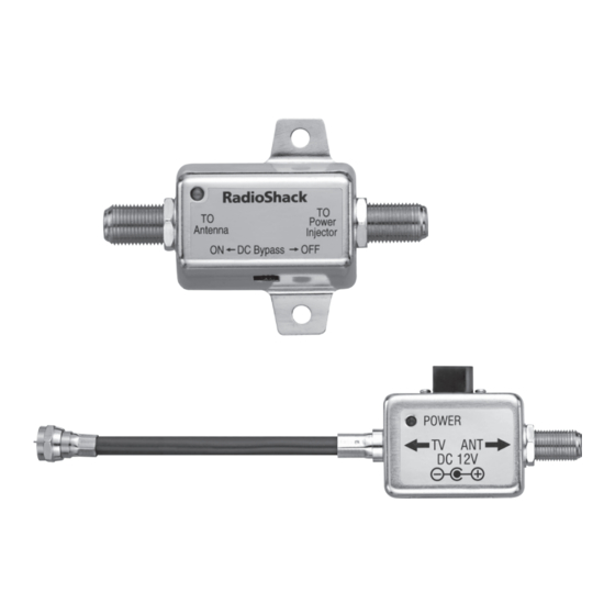
Package Contents • Signal Amplifier • Power Injector • AC Adapter • Screws (2) • User’s Guide Features • At least 12dB gain and less than 4dB noise figure at 50MHz - 900MHz to boost signal and compensate signal loss from long RF cables. • DC bypass slide switch on the amplifier. Specifications Amplifier Frequency ................50 – 900 MHz Gain ....................Min. 12 dB Noise Figure........ ..........Max. 4 dB Power Injector Input............... ......12V DC Insertion Loss................Max. 3 dB AC/DC Adapter Input . - Page 3 3. The amplifier should be situated so that its location does not interfere with its proper ventilation. 4. This amplifier should be connected to a power supply of the type described in the operating instructions or marked on the amplifier. 5. Do not attempt to destroy the grounding or polarization components of this amplifier. 6. Wipe the amplifier with a damp cloth occasionally to keep it looking new. Do not use harsh chemicals, cleaning solvents, or strong detergents to clean the amplifier. 7. The power cord of the amplifier should be unplugged from the outlet when left unused for extended periods of time. 8. Do not allow liquids to spill through the amplifier’s openings. 9. An outside antenna system should not be located in the vicinity of overhead power lines or other electric light or power circuits, or where it can fall into such power lines or circuits. When installing an outside antenna system, extreme care should be taken to keep from touching such power lines or circuits as contact with them might be fatal. 10. Place the amplifier away from heat sources such as radiators, heat registers, stoves, or other appliances. 11. Temperature extremes can shorten the life of electronic devices and distort or melt plastic parts.
- Page 4 12. If an outside antenna is connected to the receiver, be sure the antenna system is grounded to provide some protection against voltage surges, built-up static charges, and lightning strikes. Section 810 of the National Electric Code (NEC), ANSI/NFPA NO. 70-70-1990, provides information with respect to proper grounding of the mast and supporting structure, grounding of the lead-in wire to an antenna discharge unit, size of grounding conductors, location of antenna-discharge unit, connection to grounding electrodes, and requirements for the grounding electrode. Caution: Because the Amplifier uses a coaxial cable to • carry the signal from the DC power supply, proper connections are crucial. Carefully follow all instructions in this User’s Guide to avoid damage to your equipment.
-
Page 5: Select A Location
Select a Location Place your amplifier close to your input source (external antenna); place the power injector close to your receiver (TV) and an AC outlet. You can mount the amplifier on a wall or another surface using the two supplied screws. • To keep exposed cable to a minimum, you can place the amplifier in your attic. • Do not place the amplifier outdoors. • To prevent interference, do not place the amplifier within six inches of any other electronic device. Route Cables Route a 75-ohm (RG-6 or RG-6QS) coaxial cable (not supplied) from the amplifier to your input source and between amplifier and power injector. Follow these hints when routing cable: • Use only as much cable as is necessary to reach from the amplifier to the input source and receiver. • Do not route cables where they might be cut, crimped, or crushed by normal activities. - Page 6 Connect to Antenna Connecting a Passive Antenna Connect the TO Antenna side of the amplifier to the antenna transformer OR as close to the antenna as possible if it does not have a transformer. External Passive Indoor Antenna RF Cable Slide to ON Second Amplifier with ON/OFF slide to OFF -OR- Indoor Outdoor Slide to OFF...
- Page 7 Connecting an Amplified Antenna Refer to “Connecting a Passive Antenna” and follow the connection labeling on the amplifier and power injector to connect devices. If the current consumption of the amplified antenna is higher than 100mA, use the power injector of the amplified antenna. Indoor Adapter of External External Amplified Amplified Antenna Antenna Slide to OFF Power Injector of External Amplified Antenna -OR- Indoor Outdoor Slide to ON...
-
Page 8: Connect To Receiver
Connect to Receiver 1. Connect the TO ANT side of the power injector to the amplifier using a coaxial cable with F-type connectors (not included). 2. Connect the TO TV side of the power injector to one receiver OR to a 75 ohm splitter (not included) and two receivers. 3. Double-check all connections. Connect the supplied AC adapter to the power injector’s DC 12V jack, then plug it into a standard household outlet. The amplifier’s red LED lights when it has power. You can use a RF cable (not included) up to 150 feet (46 m) to connect an extra second amplifier in-line with the first amplifier to enhance the RF signal level. Coaxial Cable HDTV -OR- 75 ohm Splitter... -
Page 9: Troubleshooting
Notes: • You must follow the connection labeling on the amplifier: To Antenna and To Power Injector. The amplifier will not receive power if it is reversed. • You must follow the connection labeling on the power injector: To TV and To ANT. Your TV or receiver will be damaged if it is reversed. -
Page 10: Limited Warranty
(b) replace the product with the same or a comparable product; or (c) refund the purchase price. All replaced parts and products, and products on which a refund is made, become the property of RadioShack. New or reconditioned parts and products may be used in the performance of warranty service. Repaired or replaced parts and products are warranted for the remainder of the original warranty period. You will be charged for repair or replacement of the product made after the expiration of the warranty period. RADIOSHACK EXPRESSLY DISCLAIMS ALL WARRANTIES AND CONDITIONS NOT STATED IN THIS LIMITED WARRANTY. ANY IMPLIED WARRANTIES THAT MAY BE IMPOSED BY LAW, INCLUDING THE IMPLIED WARRANTY OF MERCHANTABILITY AND, IF APPLICABLE, THE IMPLIED WARRANTY OF FITNESS FOR A PARTICULAR PURPOSE, SHALL EXPIRE ON THE EXPIRATION OF THE STATED WARRANTY PERIOD. EXCEPT AS DESCRIBED ABOVE, RADIOSHACK SHALL HAVE NO LIABILITY OR RESPONSIBIL- ITY TO THE PURCHASER OF THE PRODUCT OR ANY OTHER PERSON OR ENTITY WITH RESPECT TO ANY LIABILITY, LOSS OR DAMAGE CAUSED DIRECTLY OR INDIRECTLY BY USE OR PERFORMANCE OF THE PRODUCT OR ARISING OUT OF ANY BREACH OF THIS WARRANTY, INCLUDING, BUT NOT LIMITED TO, ANY DAMAGES RESULTING FROM INCON- VENIENCE AND ANY LOSS OF TIME, DATA, PROPERTY, REVENUE, OR PROFIT AND ANY INDIRECT, SPECIAL, INCIDENTAL, OR CONSEQUENTIAL DAMAGES, EVEN IF RADIOSHACK HAS BEEN ADVISED OF THE POSSIBILITY OF SUCH DAMAGES. Some States do not allow limitations on how long an implied warranty lasts or the exclusion or limitation of incidental or consequential damages, so the above limitations or exclusions may not apply to you. This warranty gives you specific legal rights, and you may also have other rights RadioShack Customer which vary from State to State. You may contact RadioShack at: Relations 300 RadioShack Circle, Fort Worth, TX 76102 04/08 www.RadioShack.com Protect the environment by recyling used electronics. Go to E-CyclingCentral.com to find an electronic recycling center near you. ©2010. RadioShack Corporation. All rights reserved. RadioShack and RadioShack.com are Printed 08A10 trademarks used by RadioShack Corporation. in China 1500369 AO0447AAA1...
Need help?
Do you have a question about the 1500369 and is the answer not in the manual?
Questions and answers