Advertisement
Quick Links
System LST
Low Surface Temperature Natural Convector
Installation Instructions
Dunham-Bush Ltd, Downley Road, Havant, Hants PO9 2JD
Tel. 023 9247 7700
(Global) www.dunham-bush.com
(UK) www.dunham-bush.co.uk
NOTE: PLEASE LEAVE COPIES OF THESE INSTRUCTIONS AND ANY DRAWINGS WITH THE END USER.
INTRODUCTION
This booklet provides guidance for the site activities necessary to identify, handle, install, commission and service
Dunham-Bush System LST Low Surface Temperature Natural Convector.
The instructions refer to the standard product only: please refer to any additional drawings supplied for details of
any special features. Please study all documentation carefully before commencing installation work.
IDENTIFICATION
Refer to diagrams for exploded views and identification of the main parts. Any reference given on the order will be
marked on the casing, back plate and emitter packages for site identification.
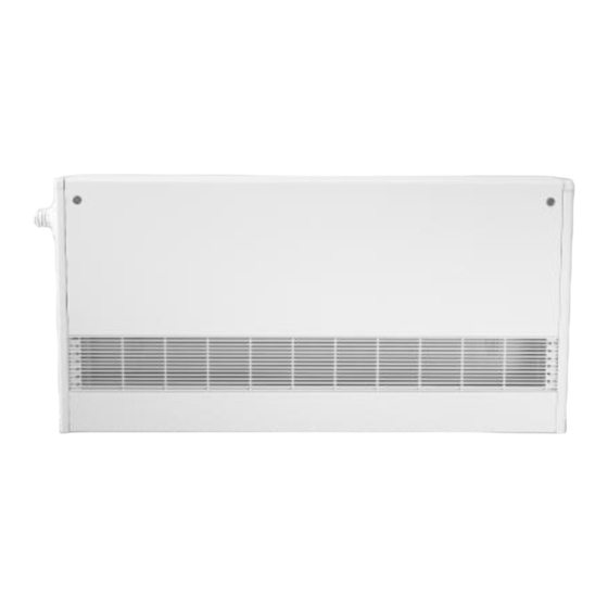
DESCRIPTION
Each System LST natural convector consists of a back plate, emitter and casing components as shown in the
Diagrams.
Lock shield valves and TRV kits are optional accessories.
HANDLING
Casings, back plates and emitters are usually packed separately. Small orders may be packed in boxes and can
usually be off-loaded by hand. Larger orders are usually palletised and lifting equipment should be provided by the
buyer. Care should be taken when handling to avoid damage.
STORAGE
System LST components should be stored under dry, clean conditions. Any protective packing should not be
removed until the components are required for installation, unless damage in transit is suspected. (Note: The buyer
must examine the goods promptly upon arrival and is not entitled to make any claim against the Company in
respect of damaged goods, unless at the time of delivery the 'delivery note' is endorsed by the buyer and
countersigned by the carrier or shipping agent with a note detailing the damage).
PREPARATION
A sound, flat, vertical surface is necessary. The screws fixing the casing to the vertical surface are integral to the
structure of the casing hence suitable screws and if necessary, wall plugs must be provided by others, for fixing
back plates to the vertical surface.
Any obstructions or hazards within the wall such as live electrical cables and pipework must first be identified before
installation commences.
INSTALLATION
Before commencing any work identify the correct LST radiator for the location. If a radiator reference was given on
the order this will be marked on the packages for site identification.
WARNING
Some internal components have sharp edges. Care must be taken when installing this product and it is
recommended that protective gloves are worn.
Fax. 023 9245 3601
Document Ref:
105-000-001-D
Date : February 2016
Page 1 of 16
Advertisement

Subscribe to Our Youtube Channel
Related Manuals for Dunham-Bush System LST


Summary of Contents for Dunham-Bush System LST
-
Page 1: Installation Instructions
DESCRIPTION Each System LST natural convector consists of a back plate, emitter and casing components as shown in the Diagrams. Lock shield valves and TRV kits are optional accessories. - Page 2 By applying test results through a mathematical model, Dunham-Bush engineers have developed a Selection Program to help the heating designer optimise their radiator schedules for all conceivable LPHW conditions. BSRIA tested to BS EN 442 heating performance and NHS Guidance touch temperatures, System LST is a complete solution for safe efficient heating.
-
Page 3: Installation Sequence
INSTALLATION SEQUENCE Backplates Fix) Emitters &Valves Fix) Sideplates Fix) Grilles Fix) Casings Fix) Page 3 of 16... - Page 4 CASING STYLES Dunham-Bush System LST is available in four styles, A, B, C & D (pictured below). Style A casing Style B casing Style D casing Style C casing Page 4 of 16...
- Page 5 Style A – 97mm Element Emitter Style A – 97mm Radiator Panel Style A – 161mm Element Emitter Style A – 161mm Radiator Panel Page 5 of 16...
- Page 6 Style B – 97mm Element Emitter Style B – 97mm Panel Emitter Style B 161mm Element Emitter Style B 161mm Panel Emitter Page 6 of 16...
- Page 7 Style C – 97mm Element Emitter Style C – 97mm Panel Emitter Style C – 161mm Element Emitter Style C – 161mm Panel Emitter Page 7 of 16...
- Page 8 Style D – 161mm Element Emitter Style D – 161mm Panel Emitter Style D – 260mm Element Emitter Page 8 of 16...
- Page 9 System LST Installation - First Fix Mark positions of fixings on the wall using the back plate as a template. Note: recommended fixing height of 100mm above FFL (Style A), styles B, C & D can be fixed at FFL or onto pipe boxing/trunking. There are a large number of holes provided, as minimum we recommend fixing to every fourth hole along the top and bottom edges plus 2 to 3 fixings down the sides.
- Page 10 Diagram 2a Styles A, B & C. Refer to bracket table for details of required brackets for each emitter type. Diagram 2b Style D. Refer to bracket table for details of required brackets for each emitter type. Page 10 of 16...
- Page 11 Diagram 3 Hang the panel radiator or finned element on the brackets as centrally as possible. Fit any lock shield valves and/or TRV valve body. (When fitting a Herz TRV; fit pipe insert (provided) and valve fittings must be assembled using spray silicone oil and compression nuts must be tightened clockwise ¾ of a turn / 270 degrees).Note only casings styles B, C &...
- Page 12 System LST Installation - Second Fix Ensure panel radiator is clean or that the finned element is clean and fins are not crushed, before fitting casing. Diagram 5 Position the side plates at either end of the back plate using the studs for alignment (see detail in Diagram 4).
- Page 13 Remove the TRV Blanking plate from the side plate nearest the TRV valve body. Diagram 6a Wind the surplus length of the capillary around the TRV dial into the groove provided ensuring that it will not be tight when fitted. Diagram 6b Insert the bellows housing through the aperture in the side plate of the casing.
- Page 14 Affix the Sensor/Set point TRV Dial to the side of the casing using the screws provided. Diagram 7a Attach the bellows housing to the TRV valve body using the knurled nut. Diagram 7b Clip on the cover to the TRV dial Diagram 7c Page 14 of 16...
- Page 15 Fit the grilles. On the top grille insert the tab into the slot at an angle with the large rectangular notch towards the front of the heater. Diagram 8a Pull the grille towards you so that the edge of the slot is in the notch.
-
Page 16: Maintenance
SPARES/SERVICE Spare parts/service – Please contact our office, contact information shown below. Manufacturer reserves the right to change any product specification without notice. Dunham-Bush Ltd, Downley Road, Havant, Hants, PO9 2JD Sales and Technical Support Spare Parts and Service Tel: 023 9247 7700...
Need help?
Do you have a question about the System LST and is the answer not in the manual?
Questions and answers