Table of Contents
Advertisement
Quick Links
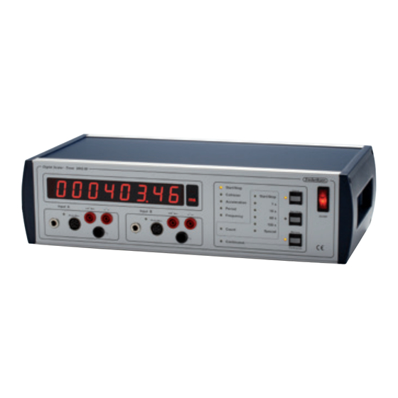
Manual for Electronic counter
27.09.13
Stopwatch
• Simple start/stop-function
• Velocities before and after collisions
• Acceleration
• Period
• Frequency counter
Counter
• Counting with manual timing
• Counting for 1, 10, 60 or 100 seconds
• Single or repeated count
INPUTS
In both groups A and B, there are four types of in-
puts. Only one of these are used in each group.
Jack socket
Typically, this input is used with our GM sensors
5135.70 and 5135.65, our Geiger counter 5136.00,
coincidence-box 5138.00 as well as various equip-
ment with Jack plug from Pasco.
DIN connector
This input is used to photocells (1975.50 and
1975.15) and microphones (2485.10) from Frederik-
sen. (Older models of sensors and microphones can
usually also be connected via an adapter.)
A/S Søren Frederiksen, Ølgod
Viaduktvej 35 · DK-6870 Ølgod
Tel. +45 7524 4966
info@frederiksen.eu
Fax +45 7524 6282
www.frederiksen.eu
QUICK-GUIDE
As a general rule: An LED turned on indicates an
active function. A flashing LED indicates a possible
choice.
Connect a signal source to one of the inputs in
group A (and eventually one in B). The inputs in each
group are equal.
Select the function by rapidly pressing the Select
button until the desired mode is selected. The func-
tion is selected when you pause (about 1 second).
Counting interval for the Count function: When
Count is selected, continued pressing of the
Select button selects the counting period.
Repeated measurements for Period, Frequency, or
Count: When the Continuous LED is flashing, press
the Memory/Continuous button. The LED lights up
steadily.
Memory: For instance Collision will provide up to
four results. The LED next to the button Memory/
Continuous will flash to indicate that memory con-
tains data. Press the button to switch between them.
Resetting after a measurement is made by pressing
Select once.
Be sure to position the DIN connector
correctly in the socket! It is possible
to brutally force the plug in, even if it
is upside down – which will usually de-
stroy the connected equipment.
This entry consists of the left of the two red safety
sockets (signal) and the black (ground). A typical
application is our free fall apparatus, but all types of
switches can be used.
This input consists of the right of the two red
safety sockets (signal) and the black (ground).
All kinds of (positive) electrical pulses can be
used with this entry. (For example, older types of
Geiger counters provide a pulse output with plugs
that match this input.)
2002.50 AE
®
Advertisement
Table of Contents

Related Manuals for Frederiksen Electronic counter


Summary of Contents for Frederiksen Electronic counter
- Page 1 Manual for Electronic counter 27.09.13 2002.50 AE QUICK-GUIDE As a general rule: An LED turned on indicates an active function. A flashing LED indicates a possible choice. Connect a signal source to one of the inputs in group A (and eventually one in B). The inputs in each group are equal.
- Page 2 In contrast to the other inputs, the pulse inputs are Acceleration not identical; in group A, the pulse input is more sen- This function is used with two photocells a car or sitive than in group B. cart equipped with a ”tab” that can interrupt the light to the photocell.
- Page 3 Press the Select button repeatedly until the Period Shortly after you select the measurement period, LED is lit. After a short time the Continuous LED will the Continuous LED flashes and normally you will flash and normally you will now press Memory/Con- now press the Memory/Continuous to achieve conti- tinuous to achieve continuously repeated measure- nuously repeated measurements.
- Page 4 The Microphone input triggers on the falling slope at c. 0.5 V. Sensitivity can be raised about 10 dB by shorting the Photo input to ground. Apart from this, the Photo input is strongly specia- lized for use with Frederiksen’s photocell units. Switch input Triggering occurs on the rising slope – i.e. when the switch breaks – at c. 1.2 V.
Need help?
Do you have a question about the Electronic counter and is the answer not in the manual?
Questions and answers