Table of Contents
Advertisement
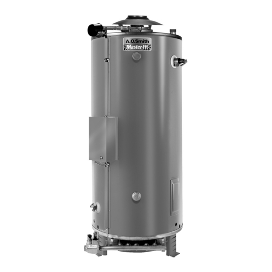
Service Handbook
COMMERCIAL GAS HIGH EFFICIENCY WATER HEATERS
FOR MODELS:
BTR 120 thru 400(A) Series 118 & 119
INSTALLATION CONSIDERATIONS - PRE SERVICE CHECKS -
CONSTRUCTION - OPERATION & SERVICE - TROUBLESHOOTING
500 Tennessee Waltz Parkway
Ashland City, TN 37015
SERVICING SHOULD ONLY BE PERFORMED BY A QUALIFIED SERVICE TECHNICIAN
100277701_2000536453_Rev A
PRINTED IN THE U.S.A. 1016
Advertisement
Table of Contents
Troubleshooting


Need help?
Do you have a question about the BTR 120-400 and is the answer not in the manual?
Questions and answers