Table of Contents
Advertisement
Quick Links
Overview
This Operating Manual covers information on safety and cautions. Please
read the relevant information carefully and observe all the Warnings and
Notes strictly.
Warning
To avoid electric shock or personal injury, read the "Safety
Information" and "Rules for Safe Operation" carefully before using the
Meter.
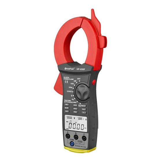
This is a three phase intelligent handheld digital power clamp meter
(hereafter referred to as "the Meter") which has both the features of digital
current meter and also power measurement meter.
The Meter can measure Voltage, Current, Active Power, Apparent Power,
Reactive Power, Power Factor, Phase Angle, Frequency, Active Energy and
etc.
Unpacking Inspection
Open the package case and take out the Meter. Check the following items
carefully to see any missing or damaged part:
Item
1
2
3
4
5
6
7
8
9
10
11
12
13
Description
English Operating Manual
Red Test Lead
Black Test Lead
Blue Test Lead
Yellow Test Lead
Red Alligator Clip
Black Alligator Clip
Blue Alligator Clip
Yellow Alligator Clip
USB Interface Cable
Software
Tool Box
9 V Alkaline batteries
1
Qty
1 piece
1 piece
1 piece
1 piece
1 piece
1 piece
1 piece
1 piece
1 piece
1 piece
1 piece
1 piece
1 pieces
Advertisement
Table of Contents

Related Manuals for HP 850F


Summary of Contents for HP 850F
-
Page 1: Overview
Overview This Operating Manual covers information on safety and cautions. Please read the relevant information carefully and observe all the Warnings and Notes strictly. Warning To avoid electric shock or personal injury, read the “Safety Information” and “Rules for Safe Operation” carefully before using the Meter. -
Page 2: Safety Information
In the event you find any missing or damage, please contact your dealer immediately. Safety Information This Meter complies with the standards IEC61010: in pollution degree 2, overvoltage category (CAT. III 600V,CAT IV 300V) and double insulation. CAT. III: Distribution level, fixed installation, with smaller transient overvoltages than CAT. - Page 3 the Meter power off. Do not carry out the measurement when the Meter’s back case and / or battery door is opened to avoid electric shock. When the Meter working at an effective voltage over 30V in AC, special care should be taken. Use the proper terminals and function for your Measurements....
-
Page 4: International Electrical Symbols
International Electrical Symbols AC (Alternating Current) Grounding Double Insulated Warning. Refer to the Operating Manual Deficiency of Built-In Battery Danger of High Voltage Conforms to Standards of European Union The Meter Structure A. - Page 5 1 Transformer Jaw: designed to pick up the AC and DC current flowing through the conductor. It could transfer current to voltage. The tested conductor must vertically go through the Jaw center Hand Guards: to protect user’s hand from touching the dangerous area....
-
Page 6: Functional Buttons
B. Button operation performed Button Operation Performed ● Press HOLD to enter the Hold mode in any mode, appears and the Meter beeps. HOLD ● Press HOLD again to exit the Hold mode to return to measurement mode, the Meter beeps and disappears. - Page 7 ●At Active power (main display) + Phase angle (secondary display) mode, press ∑once button to sum up the current ∑ first phase of 3 phase measurement result. Then carry out second phase power measurement. ● Press ∑ again to sum up the second phase power measurement result, then carry out third phase power measurement.
-
Page 8: Display Symbols
Display Symbols (see figure 3) figure 3... - Page 9 Number Symbol Meaning First phase symbol Second phase symbol Third phase symbol Unit for hour Unit for minute ∑W Watt: Sum of Watt The battery is low. Warning: To avoid false readings, which could lead to possible electric shock or personal injury, replace the battery as soon as the battery indicator appears.
-
Page 10: Measurement Operation
Measurement Operation Preparation ● 。 Turn on Rotary Switch ●Replace the battery as soon as the battery indicator “ ” appears on the display. A. AC Voltage (main display) + Frequency (secondary display) Measurement (see figure 4) figure 4 The AC Voltage ranges are:15V, 100V, 300V and 600V The frequency range is:20Hz~100Hz To measure AC voltage + frequency, connect the Meter as follows:... -
Page 11: Ac Current + Ac Voltage Measurement
1. Insert the red test lead into the V A terminal, blue test lead into the V B terminal, yellow test lead to V C input terminal and black test lead to the COM input terminal. 2. Connect the red test leads (VA input terminal), blue test leads (VB input terminal) and yellow test leads (VC input terminal) to the corresponding three phases loaded live wire. -
Page 12: Active Power + Phase Angle Measurement
otherwise it will cause deviation. The Meter can only measure one conductor at a time, to measure more than one conductor at a time will cause deviation. 4. The double display shows the AC current True RMS value and AC voltage True RMS value. - Page 13 figure 6 Insert red test leads to A input terminal. Insert blue test leads to B input terminal Insert yellow test leads to C input terminal and connecting it to every live wire of the 3 phase. Insert black test leads to COM input terminal and connect it to the neutral wire of the 3 phase.
- Page 14 ●When measuring 3 phase 3 wires, connect the Meter as figure 7. figure 7 Insert red test leads to A input terminal. Insert blue test leads to B input terminal Insert black test leads to COM input terminal and connect it to the neutral wire of the 3 phase.
- Page 15 figure 8 Insert red test lead to A, B or C input terminal corresponding to one C phase Insert black test leads to COM input terminal. Connecting the two test leads to live and neutral wires. 4. When measuring 3 phases 4 wires:(see figure 9, 10, 11, 12, 13, 14, 15, ●...
- Page 16 figure 9 ● If necessary, press∑ to get the sum of watts as figure 10. figure 10 ● After sum up the current power measurement value of the first phase, then press SELECT to choose the second phase B, as figure 11 figure 11 ●...
- Page 17 ● If necessary, press∑ to get the sum of watts as figure 12. figure12 ● After sum up the current power measurement value of the second phase, then press SELECT again to choose the third phase C, as figure 13. figure 13 ●...
- Page 18 finally press SELECT again to display the 3 phase sum of active power value and reactive power value. ● Press MAX/▲ or MIN/ ▼as figure 15 to step through in sequence three phase sum of active power+ three phase sum of reactive power, and three phase sum of power factor + 3 phase sum of apparent power.
-
Page 19: Apparent Power + Reactive Power Measurement
when it is over than that. The maximum range is 1800kW of three phase sum of active power, 9999 will be displayed when it is over than that. 7. Press MAX/▲ , the display shows MAX, it starts recording the maximum active power value. - Page 20 figure 17 ● The double display shows the first phase value of apparent power kVA and reactive power Kvar. Then press SELECT again to choose the second ● phase B, see figure 18. figure 18 ● The double display shows the second phase value of apparent power kVA and reactive power Kvar.
-
Page 21: Power Factor + Phase Angle Measurement
5. When measuring 3 phase 3 wires: ● The first phase and second phase operating method is same as three phase 4 wires. ● Jump over the third phase measurement. 6. The maximum measuring range is 600kW when measuring single phase apparent power kVA and reactive power Kvar, 9999 will be displayed when it is over than that. - Page 22 figure 20 ● The double display shows the first phase value of power factor PF and phase angle PG. ● Then press SELECT again to choose the second phase B, see figure figure 21 ● The double display shows the second phase value of power factor PF and phase angle PG.
-
Page 23: Active Energy + Time Measurement
5. When measuring 3 phase 3 wires: ● The first phase and second phase operating method is same as three phase 4 wires. ● Jump over the third phase measurement. 6. MAX/ ▲and MIN/▼ are not valid when measuring power factor. Note ●... -
Page 24: Phase Angle + Voltage + Current
kWh value and the measuring time of the corresponding phase. ● The measuring reading gets increasing along with the time increases. Press HOLD to read a particular time kWh value. Then the reading and time are locked, but still continuous accumulate measuring time. ●... -
Page 25: Frequency + Voltage + Current
The double display shows the φA value of phase Angle φ,Voltage value and also Current value. Then press SELECT to choose Second phase φB figure 25 The double display shows the φB value of phase Angle φ,Voltage value and also Current value. Then press SELECT to choose Second phase φC figure 26 Measuring 1 phase and 2 phase as same as 3 phase 4 wires. - Page 26 (3)The connecting method of 3 phases 4 wires, 3 phases 3 wires or single phase 2 wires, see figure 4, 5 and 6 (4) Press SELECT to choose the first phase φA. See figure 27. figure 27 The double display shows the φA value of Frequency Hz Voltage value and also Current value.
-
Page 27: Active Energy + Active Power + Time
4 wires. Jump over the third phase measurement (5) This feature file, no maximum and minimum measurement Warning To avoid damages to the meter or harms to you,do you measure higher than AC voltage 600(r.m.s )and AC Current 1000A (r.m.s) Frequency measurement is the voltage signal measured the frequency, not the current signal of frequency。... -
Page 28: Phase Sequence Detection
figure30 Warning 1) To avoid damages to the meter or harms to you,do you measure higher than AC voltage 600(r.m.s )and AC Current 1000A (r.m.s) No signal excluding the measurement of power, signal input, needs to wait for a maximum time of 10 S start time. 3) The data is not saved after power off, After reboot re-count J Phase sequence detection (1)Turn on Rotary Switch to select “RST ”,(figure 30) - Page 29 test lead into “VC” hole, Put black test lead into “COM” hole. And put the four test pens connected to the await measuring power supply or load side of three-phase and ground terminal. For the three-phase four-wire loading return circuit, Meter displays the phase sequence test results. (2)Three horizontal line from top to bottom on behalf of A, B, C phase, Such as lack of one phase, will be displayed.
-
Page 30: True Rms Measurement And Average Value Measurement
Figure 27 Positive sequence arrange is shown below, “A” hole , “B” hole and “C” hole are connect A phase, B phase, C phase according to below form, and when the three phase voltage is beyond 100v , LCD display Positive sequence test results. In Figure 35 positive sequence hole A、B、C phasic... -
Page 31: General Specifications
A. General Specifications ● Maximum Voltage between any Terminals and grounding: Refer to different range input protection voltage. ● Display: Multi LCD displays, Maximum display 9999. ●Ranges: Auto ● Overloading: Display 9999. ● Battery Deficiency: Display . ● Data Holding: Display ●... -
Page 32: Accuracy Specifications
40 ~ 50 ( 45%R.H) Storage:-10 ~ +60 ( 85%R.H) ● Safety/ Compliances: IEC 61010 CAT.III 600V, CAT.IV 300V overvoltage and double insulation standard, pollution degree 2 ● Certification: Accurate Specifications Accuracy :± (a% reading + b digits),guarantee for 1 year. Operating temperature:23℃±... -
Page 33: Active Power
800-1000 ± (3.5%+20) · Allowable maximum overload protection current:1000A RMS D.Active Power (w=V×A×COS Ф) Voltages Range Current/Voltage 100V 300V 600V 0.60kW 4.00kW 12.00kW 24.00kW 100A 1.50kW 10.00kw 30.00kW 60.00kW Current 400A 6.00kW 40.00kW 120.0kW 240.0kW Range 1000A 15.00kW 100.0kW 300.0kW 600.0kW Accuracy ±... -
Page 34: Reactive Power
Remarks: .Min Input Voltage:10V · Allowable maximum overload protection voltage:600V RMS · Allowable maximum overload protection current:1000A RMS F. Reactive Power (Var =V×A×SINФ) Voltages Range Current/Voltage 100V 300V 600V 0.60kVar 4.00kVar 12.00kVar 24.00kVar 100A 1.50kVar 10.00kVar 30.00kVar 60.00kVar Current 400A 6.00kVar 40.00kVar 120.0kVar... -
Page 35: Phase Angle
· Min Input Voltage:10V · Allowable maximum overload protection voltage:600V RMS · Allowable maximum overload protection current:1000A RMS H. Phase Angle ( PG =acos (PF)) Range Accuracy Resolution Measuring Condition The minimum measuring current 10A 0° ~360° ± 1° 1° The minimum measuring voltage 45V Measuring current less than 10A OR 0°... - Page 36 in the terminals can affect readings. ● Turn the Meter power off when it is not in use. ● Take out the battery when it is not using for a long time. ● Do not use or store the Meter in a place of humidity, high temperature, explosive, inflammable and strong magnetic field.
-
Page 37: Table Of Contents
TABLE OF CONTENTS TITLE PAGE Overview…………………………………………………………………………. 1 Unpacking Inspection…………………………………………………………... 1 Safety Information………………………………………………………………. 2 Rules For Safe Operation……………………………………………………… 2 International Electrical Symbols………………………………………………..4 A. The Meter Structure………………………………………………………….4 B. The Meter Front Structure…………………………………………………...4 Functional Buttons……………………………………………………………….6 Display Symbols…………………………………………………………………8 Measurement Operation………………………………………………………..10 A. AC Voltage + Frequency Measurement…………………………………...10 B. - Page 38 I. Active Energy………………………………………………………………….35 Maintenance……………………………………………………………………..35 A. General Service………………………………………………………………35 B. Replacing the Battery………………………………………………………..36...
- Page 39 OPERATING MANUAL DIGITAL POWER CLAMP METER 850F...
Need help?
Do you have a question about the 850F and is the answer not in the manual?
Questions and answers