Table of Contents
Advertisement
Advertisement
Table of Contents

Related Manuals for Air Liquide T 150i AC/DC

Summary of Contents for Air Liquide T 150i AC/DC
- Page 1 The technical specifications and the wiring diagrams contained in this owner’s manual are valid only for the model that has the part number indicated below. T 150i AC/DC ALW-M170500182 Air Liquide Welding is a trademark of L’Air Liquide S.A. 08/01...
-
Page 2: Table Of Contents
.........14 T 150i AC/DC SPARE PARTS LIST... -
Page 3: Safety Precautions - Read Before Using
The publisher does not assume and hereby disclaims any liability to any party for any loss or damage caused by any error or omission in the Air Liquide T 150i AC/DC Owner’s Manual, whether such error results from negligence, acci- dent or any other causes. -
Page 4: Fire And Explosion Prevention
4. Beware of gas leaks. Shielding gases such as argon are heavier than air and when used in small spaces, will replace the air. Compressed gas cylinders are potentially dangerous. Consult the supplier 5. In the event that a welding operation occurs in for correct handling procedures. -
Page 5: Radiation Can Cause Injury
1.7 H.F. RADIATION CAN CAUSE INJURY 1.9 WELDING AND THE EFFECTS OF LOW FREQUENCY AND MAGNETIC FIELDS As welding current flows through welding cables, it High frequency (HF) emissions can can cause electromagnetic fields. To reduce mag- interfere with radio navigation, safety devices, netic fields, use the following procedures: computers and communication equipment. - Page 6 EQUIPMENT INSTALLATION AND MAINTENANCE MUST BE PERFORMED IN COMPLIANCE WITH LOCAL SAFETY STANDARDS. Electric shock could be fatal Fumes and gases may represent Use a protective mask with suit- a safety hazard. able glass filter (at least NR10) to 1. Never touch exposed electrical Fumes and gases generated dur- safeguard eyes.
-
Page 7: Specification And Description
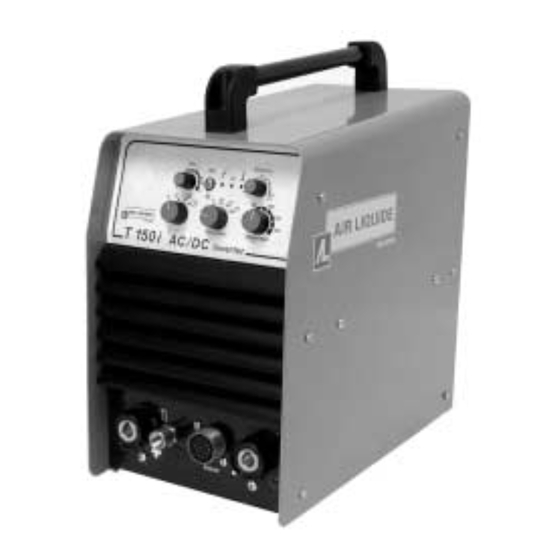
2. SPECIFICATIONS AND DESCRIPTION 2.1 SPECIFICATIONS 2.2 DESCRIPTION The T 150i AC/DC sets a new standard for constant stick, hot start and arc force will ensure ease of current, AC/DC arc welding inverters. This 230-volt operation and increased operator satisfaction. This... -
Page 8: Duty Cycle And Overheating
To correct this situation, wait fifteen minutes for the unit to cool. Reduce amperage or duty cycle before starting to weld again. T 150i AC/DC Duty Cycle Curve STICK % DUTY CYCLE • Exceeding the duty cycle can damage the unit and void the warranty. -
Page 9: Operation
3. OPERATION 3.1 FRONT PANEL CONTROLS BALANCE CONTROL This control operates when the unit is set in the AC welding mode. It is used to adjust the positive side AMPERAGE ADJUSTMENT CONTROL. of the waveform with respect to the negative side This control is used to adjust welding amperage. -
Page 10: Back Panel Controls
For Stick welding using electrodes that operate on DCEN (Direct Current Electrode Negative), connect the electrode cable to this receptacle. For TIG welding, connect the TIG torch cable to this receptacle. 11. REMOTE 14 PIN RECEPTACLE SOCKET (*) SOCKET INFORMATION TRIGGER TRIGGER HIGH-END POTENTIOMETER... -
Page 11: Installation
4. INSTALLATION 4.3 CONNECTION AND PREPARATION OF Before connecting, preparing or using EQUIPMENT FOR STICK ELECTRODE equipment, read Section 1: Safety Precautions. WELDING 4.1 CONNECTING THE EQUIPMENT TO THE Connect all welding accessories carefully to pre- MAIN SUPPLY vent power loss. Carefully follow safety precau- tions described in Section 1. -
Page 12: Connection And Preparation Of Equipment For Gtaw (Tig)
4.4 CONNECTION AND PREPARATION OF EQUIPMENT FOR TIG WELDING Connect all welding accessories carefully to avoid power loss or leakage of dangerous gases. Carefully follow the safety standards described in Section 1. T U R N O F F W E L D E R B E F O R E M A K I N G CONNECTIONS. -
Page 13: Maintenance And Troubleshooting
5. MAINTENANCE AND TROUBLESHOOTING Disconnect power before maintenance. Service more often during severe conditions. 5.1 ROUTINE MAINTENANCE Disconnect the power source from power supply the machine with dry compressed air to remove dirt and dust. before performing any maintenance work. Periodically, remove the side panels and blow out Increase the frequency of cleaning when operating in dirty or dusty conditions. -
Page 14: T 150I Ac/Dc Electrical Diagram
6. T 150i AC/DC ELECTRICAL DIAGRAM... -
Page 15: T 150I Ac/Dc Spare Parts List
7. T 150i AC/DC SPARE PARTS LIST...
Need help?
Do you have a question about the T 150i AC/DC and is the answer not in the manual?
Questions and answers