Table of Contents
Advertisement
Published on LabJack (http://labjack.com)
Home > UE9 User's Guide
UE9 User's Guide
This is the complete user's guide for the UE9, including documentation for the LabJackUD driver.
Includes specifications in Appendix A.
To make a PDF of the whole manual, click "Export all" towards the upper-right of this page. Doing so
converts these pages to a PDF on-the-fly, using the latest content, and can take 20-30 seconds.
Make sure you have a current browser (we mostly test in Firefox and Chrome) and the current version
of Acrobat Reader. If it is not working for you, rather than a normal click of "Export all" do a right-click
and select "Save link as" or similar. Then wait 20-30 seconds and a dialog box will pop up asking
you where to save the PDF. Then you can open it in the real Acrobat Reader, not embedded in a
browser. If you still have problems, try the "Print all" option instead. In addition, an export is attached
below, but will not always be the latest version.
If you are looking at a PDF or hardcopy, realize that the original is an online document at http://labjack.com/support/ue9/users-
guide.
Rather than using a PDF, though, we encourage you to use this web-based documentation. Some advantages:
We can quickly change or update content.
The site search includes the user's guide, forum, and all other resources at labjack.com. When you are looking for
something try using the site search.
For support, try going to the applicable user's guide page and post a comment. When appropriate we can then immediately
add/change content on that page to address the question.
One other trick worth mentioning, is to browse the table of contents to the left. Rather than clicking on all the links to browse, you
can click on the small black triangles to expand without reloading the whole page.
User's Guide
File attachment:
UE9_UG_Export_04282011.pdf
Preface
For the latest version of this and other documents, go to www.labjack.com.
Copyright 2012, LabJack Corporation
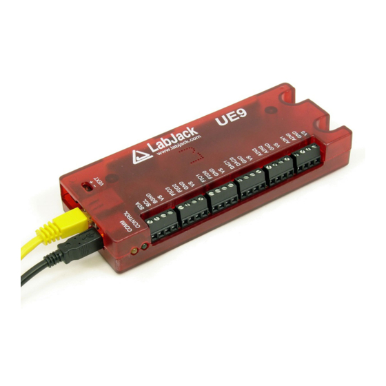
Package Contents:
The normal retail packaged UE9 or UE9-Pro consists of:
UE9 (-Pro) unit itself in red enclosure
USB cable (6 ft / 1.8 m)
Ethernet cable (6 ft / 1.8 m)
Power supply
Screwdriver
UE9 Product Page
1
Advertisement
Table of Contents

Related Manuals for LabJack UE9

Summary of Contents for LabJack UE9
- Page 1 If you still have problems, try the "Print all" option instead. In addition, an export is attached below, but will not always be the latest version. If you are looking at a PDF or hardcopy, realize that the original is an online document at http://labjack.com/support/ue9/users- guide.
-
Page 2: Installation On Windows
Although LabJacks have various redundant protection mechanisms, it is possible, in the case of improper and/or unreasonable use, to damage the LabJack and even the PC to which it is connected. LabJack Corporation will not be liable for any such damage. - Page 3 Run LJControlPanel: From the Windows Start Menu, go to the LabJack group and run LJControlPanel. Click the “Find Devices” button, and an entry should appear for the connected UE9 showing the serial number. Click on the “USB – 1” entry below the serial number to bring up the UE9 configuration panel.
- Page 4 TCP using each address in the list. On some networks this might be preferred over the UDP broadcast search. 1.2 - Self-Upgrade Application (LJSelfUpgrade) Both processors in the UE9 have field upgradeable flash memory. The self-upgrade application shown in Figure 1-4 programs the latest firmware onto either processor.
-
Page 5: Hardware Description
1. Unplug the UE9, wait 5 seconds then reconnect the UE9. Click OK then press program again. 2. If step 1 does not fix the problem unplug the UE9 and watch the Control and Control LEDs while plugging the UE9 back in. - Page 6 The UE9 has a full-speed USB connection compatible with USB version 1.1 or 2.0. This connection can provide communication and power (Vusb), but it is possible that some USB ports will not be able to provide enough power to run the UE9 at all speeds.
- Page 7 The default IP address of the UE9 is 192.168.1.209, which will generally work on a network using the 192.168.1.* subnet (unless another device is already using the .209 address). If the IP address of the UE9 needs to be changed, the easiest way is via USB with the LJControlPanel application.
-
Page 8: Channel Numbers
0.2%. Note that a reading from this channel returns Vs during the execution of the command, and Vs might dip slightly while increasing a command due to the increased current draw of the UE9, thus this reading might be slightly lower than a comparative reading from an external DMM which averages over a longer time. - Page 9 COM. If any of the AIN channel numbers passed to a UE9 function are in the range 16-127 (extended channels), the MIO lines will automatically be set to output and the correct state while sampling that channel. For instance, a channel number of 28 will cause the MIO to be set to b100 and the ADC will sample AIN1.
- Page 10 Voltage (versus ground): The analog inputs on the UE9 measure a voltage with respect to UE9 ground. When measuring parameters other than voltage, or voltages too big or too small for the UE9, some sort of sensor or transducer is required to produce the proper voltage signal.
- Page 11 If little is known about the box ground, a DMM can be used to measure the voltage of box ground compared to LabJack GND. As long as an extreme voltage is not measured, it is generally OK to connect the box ground to LabJack GND, but it is a good idea to put in a 100 Ω...
- Page 12 Linear Technologies (linear.com) is a good choice for dual-supply applications. The LT1490A only draws 40 µA of supply current, thus many of these amps can be powered from the Vm+/Vm- supply on the UE9, and can pass signals in the ±5 volt range. Since the input bias current is only -1 nA, large divider resistors such as R1 = R2 = 470 kΩ...
- Page 13 Another type of 3-wire sensor is the sinking type, where the 4-20 mA current is sourced from the positive supply, sent through the shunt resistor, and then sunk into the signal wire. If sensor ground is connected to UE9 ground, the sinking type of sensor presents a couple of problems, as the voltage across the shunt resistor is differential (neither side is at ground) and at least one side of the resistor has a high common mode voltage (equal to the positive sensor supply).
-
Page 14: Internal Temperature Sensor
There is an accessory available from LabJack called the LJTick-DAC that provides a pair of 14-bit analog outputs with a range of ±10 volts. The LJTick-DAC plugs into any digital I/O block, and thus up to 10 of these can be used per UE9 to add 20 analog outputs. - Page 15 3.3 volts as a high input. Consider the CD74ACT541E from TI (or the inverting CD74ACT540E). All that is needed is a few wires to bring VS, GND, and the signal from the LabJack to the chip. This chip can level shift up to eight 0/3.3 volt signals to 0/5 volt signals and provides high output drive current (+/-24 mA).
- Page 16 For instance, if a 24 volt signal is connected through a 22 kΩ series resistor, about 19 volts will be dropped across the resistor, resulting in a current of about 0.9 mA, which is no problem for the UE9. The series resistor should be 22 kΩ...
- Page 17 2.9.1.3 - Input: Mechanical Switch Closure To detect whether a mechanical switch (dry contact) is open or closed, connect one side of the switch to UE9 ground and the other side to a digital input. The behavior is very similar to the open-collector described above.
- Page 18 0 volts (logic low). Since the mechanical switch does not have any electrical connections, besides to the LabJack, it can safely be connected directly to GND, without using a series resistor or SGND.
- Page 19 I/O, some sort of buffer is used. Some options are a discrete transistor (e.g. 2N2222), a specific chip (e.g. ULN2003), or an op-amp. Note that the UE9 DACs can source enough current to control almost any SSR and even some mechanical relays, and thus can be a convenient way to control 1 or 2 relays.
- Page 20 750 kHz 48 MHz (System) Table 2.10-2. UE9 Timer Clock Options All timers use the same timer clock (which affects modes 0, 1, 2, 3, 4, 7, 12, and 13). The timer clock is determined by dividing the base clock by the clock divisor. The divisor has a range of 0-255, where 0 corresponds to a division of 256. There are 2 choices for the timer base clock.
- Page 21 10 microseconds. The always active UE9 system timer causes an interrupt 11.4 times per second. If this interrupt happens to be in progress when the edge occurs, a delay of about 1 microsecond is possible. If the software watchdog is enabled, the system timer interrupt takes longer to execute and a delay of a few microseconds is possible.
- Page 22 Requires 2 timer channels used in adjacent pairs (0/1, 2/3, or 4/5). Even timers will be quadrature channel A, and odd timers will be quadrature channel B. The UE9 does 4x quadrature counting, and returns the current count as a signed 32-bit integer (2’s complement).
- Page 23 2.10.1.10 - System Timer Low/High Read (Modes 10 & 11) The LabJack UE9 has a free-running internal 64-bit system timer with a frequency of 750 kHz. Timer modes 10 & 11 return the lower or upper 32-bits of this timer. An FIO line is allocated for these modes like normal, even though they are internal readings and do not require any external connections.
- Page 24 ±5.8 volts at no load and ±5.6 volts at 1 mA. Both lines have a 100 ohm source impedance, and are designed to provide 1 mA or less. This is the same voltage supply used internally by the UE9 to bias the analog input amplifier and multiplexers. If this supply is loaded more than 1 mA, the voltage can droop to the point that the maximum analog input range is reduced.
-
Page 25: Operation
LabJack with high voltages/currents. The RB12 relay board connects to the DB15 connector on the LabJack, using the 12 EIO/CIO lines to control up to 12 I/O modules. Output or input types of digital I/O modules can be used. - Page 26 Stream mode is generally best for maximum-throughput applications where latency is not so important. Data is acquired very fast, but to sustain the fast rates it must be buffered and moved from the LabJack to the host in large chunks. For example, a typical stream application might set up the LabJack to acquire a single analog input at 50,000 samples/second.
- Page 27 As samples are collected, they are placed in a 4 Mbit FIFO buffer on the UE9, until retrieved by the host. This 4 Mbit buffer can hold over 180,000 samples.
-
Page 28: External Triggering
One thing to consider when using external triggering is the buffering that takes place within the UE9 and PC. If the external signal is fairly continuous, such as in synchronized streaming, this is not a problem, but if the external trigger is more of a one-time pulse the buffering must be considered to get the data when desired. - Page 29 Windows System directory, along with a support DLL (LabJackUSB.dll). Generally this is c:\Windows\System\ on Windows 98/ME, c:\Windows\System32\ on Windows 2000/XP, and c:\Windows\SysWOW64\ on newer 64-bit Windows. Other files, including the header and Visual C library file, are installed to the LabJack drivers directory which defaults to c:\Program Files\LabJack\drivers\.
- Page 30 = eGet (lngHandle, LJ_ioGET_AIN, 3, &dblValue, 0); In the case of the UE9, the first example using add/go/get handles both the DAC command and AIN read in a single low-level call, while in the second example using ePut/eGet two low-level commands are used. Examples in the following documentation will use both the add/go/get method and the ePut/eGet method, and they are generally interchangeable.
-
Page 31: Function Reference
(or the DLL is unloaded). If OpenLabJack is called repeatedly with the same parameters, thus requesting the same type of connection to the same LabJack, the driver will simply return the same LJ_HANDLE every time. - Page 32 ConnectionType – Enter the constant for the type of connection, USB or Ethernet. pAddress – For USB, pass the local ID or serial number of the desired LabJack. For Ethernet pass the IP address of the desired LabJack. If FirstFound is true, Address is ignored.
- Page 33 *GoError, long *aResultErrors) Parameter Description: Returns: LabJack errorcodes or 0 for no error. Inputs: Handle – Handle returned by OpenLabJack(). NumRequests – This is the number of requests that will be made, and thus the number of results that will be returned. All the arrays must be initialized with at least this many elements.
- Page 34 After using AddRequest() to make an internal list of requests to perform, call GoOne() to actually perform the requests. This function causes all requests on one particular LabJack to be performed. After calling GoOne(), call GetResult() or similar to retrieve any returned data or errors.
- Page 35 Parameter Description: Returns: LabJack errorcodes or 0 for no error. Inputs: Handle – Handle returned by OpenLabJack(). IOType – The type of request. See Section 4.3. Channel – The channel number of the particular IOType. Outputs: pValue – A pointer to the result value.
- Page 36 – Must pass a buffer for the string of at least 256 bytes. Outputs: *pString – A pointer to the string representation of the errorcode. 4.2.14 - GetDriverVersion() Returns the version number of this Windows LabJack driver. Declaration: double _stdcall GetDriverVersion(); Parameter Description: Returns: Driver version.
- Page 37 Sends a reset command to the LabJack hardware. Reset causes the device to go to the reset/power-up configuration. Resetting the LabJack does not invalidate the handle, thus the device does not have to be opened again after a reset, but a Go call is likely to fail for a couple seconds after until the LabJack is ready.
- Page 38 Binary, long Reserved1, long Reserved2) Parameter Description: Returns: LabJack errorcodes or 0 for no error. Inputs: Handle – Handle returned by OpenLabJack(). Channel – The analog output channel to write to. Voltage – The voltage to write to the analog output.
- Page 39 – An array where each element is the value read from that counter if the appropriate element is set in the aReadCounters array. Array size must be equal to the number of timers available on the device. UE9:6, U6:4, U3:2 Array size must be equal to the number of counters available on the device. UE9:2, U6:2, U3:2...
- Page 40 C. 4.3.1 - Open The initial step is to open the LabJack and get a handle that the driver uses for further interaction. The DeviceType for the UE9 is: LJ_dtUE9 There are two choices for ConnectionType for the UE9:...
-
Page 41: Analog Inputs
LJ_ioPUT_DAC The following are IOTypes used to write/read the enable bit for each DAC. Note that although there is an enable bit for each DAC on the UE9, both DACs are enabled or disabled at the same time: LJ_ioPUT_DAC_ENABLE //Applies to both DACs. -
Page 42: Timers & Counters
LJ_ioGET_DIGITAL_BIT_STATE LJ_ioGET_DIGITAL_PORT //Also sets directions to input. x1 is number of bits. LJ_ioGET_DIGITAL_PORT_DIR //x1 is number of bits. LJ_ioGET_DIGITAL_PORT_STATE //x1 is number of bits. LJ_ioPUT_DIGITAL_BIT //Also sets direction to output. LJ_ioPUT_DIGITAL_PORT //Also sets directions to output. x1 is number of bits. DIR is short for direction. - Page 43 With the clock base special channel above, the following constants are passed in the value parameter to select the frequency: LJ_tc750KHZ //Fixed 750 kHz clock base. LJ_tcSYS //System clock: 48 MHz. Following is example pseudocode for configuring various timers and a hardware counter: //First, an add/go/get block to configure the timers and counters.
-
Page 44: Stream Mode
The UD driver retrieves stream data from the UE9 in the background, but if the computer or communication link is too slow for some reason, the driver might not be able to read the data as fast as the UE9 is acquiring it, and thus there will be data left over in the UE9 buffer. - Page 45 The number of samples read per loop iteration will vary, but the time per loop iteration will be pretty consistent. Since the LabJack clock could be faster than the PC clock, it is recommended to request more scans than are expected each time so that the application does not get behind.
- Page 46 LJ_ioRAW_IN When using these IOTypes, channel # specifies the desired communication pipe. For the UE9, 0 is the normal pipe while 1 is the streaming pipe. The number of bytes to write/read is specified in value (1-512), and x1 is a pointer to a byte array for the data.
- Page 47 SPI as slave devices. This serial link is not an alternative to the USB connection. Rather, the host application will write/read data to/from the UE9 over USB, and the UE9 communicates with some other device using the serial protocol. Using this serial protocol is considered an advanced topic.
- Page 48 SDA and SCL (if present) are not used for I²C. This serial link is not an alternative to the USB connection. Rather, the host application will write/read data to/from the UE9 over USB, and the UE9 communicates with some other device using the serial protocol. Using this serial protocol is considered an advanced topic.
-
Page 49: Watchdog Timer
Timeout of the watchdog on the UE9 can be specified to reset either/both processors, update the state of 1 or 2 digital I/O (must be configured as output by user), and update either/both DACs. - Page 50 testing, “config defaults” in LJCP can be used to enable the watchdog all the time, but often it is desirable to enable/disable the watchdog in user software so it is only active while that software is running. Note that some USB hubs do not like to have any USB device repeatedly reset. With such hubs, the operating system will quit reenumerating the device on reset and the computer will have to be rebooted, so avoid excessive resets with hubs that seem to have this problem.
-
Page 51: Error Codes
Warning: Defaults used instead. LJE_DEVICE_NOT_CALIBRATED Warning: Defaults used instead. LJE_NOERROR LJE_INVALID_CHANNEL_NUMBER Channel that does not exists (e.g. DAC2 on a UE9), or data from stream is requested on a channel that is not in the scan list. LJE_INVALID_RAW_INOUT_PARAMETER LJE_UNABLE_TO_START_STREAM LJE_UNABLE_TO_STOP_STREAM LJE_NOTHING_TO_STREAM... -
Page 52: General Protocol
5 - Low-level Function Reference This section describes the low-level functions of the UE9. These are commands sent over Ethernet or USB directly to the processors on the UE9. The Ethernet commands can all be sent using TCP, except for DiscoveryUDP. All commands, except stream related commands, can also be sent using UDP. - Page 53 There is a hardware method to restore parameters to the default values described below (in parentheses). Power up the UE9 with a short from FIO2<=>SCL, then remove the jumper and power cycle the device again. This also returns Control settings to factory...
- Page 54 CommFWVersion WriteMask: See general protocol description in Section 5.1. LocalID: (1) Used by higher-level functions to identify a specific LabJack. PowerLevel: (0) Not implemented. IPAddress: (192.168.1.209) The value returned by this parameter is the current IPAddress. If you write a new IPAddress, it will not take effect until after a reset, so you will not immediately read back the new address.
-
Page 55: Ip Address Filter
5.2.4 - IP Address Filter Sets a list of up to five IP addresses that are the only IP addresses that can connect to the UE9. Any unused Addresses can be set to 0xFFFFFFFF (255.255.255.255). If IP #0 is set to 0xFFFFFFFF than the feature is disabled and any IP address can connect. -
Page 56: Control Functions
There is a hardware method to restore parameters to the default values described below (in parentheses). Power up the UE9 with a short from FIO2<=>SCL, then remove the jumper and power cycle the device again. This also returns Comm (Section 5.2.1) and Watchdog (Section 5.3.13) settings to factory defaults. - Page 57 Command: Byte Checksum8 0xF8 0x06 0x08 Checksum16 (LSB) Checksum16 (MSB) WriteMask Bit 2: Update DAC defaults Bit 1: Update digital defaults Bit 0: Update power level default PowerLevel [0] 0x00: Fixed high, system clock = 48 MHZ 0x01: Fixed low, system clock = 6 MHz FIODir FIOState EIODir...
- Page 58 5.3.3 - Feedback (and FeedbackAlt) A very useful function that writes/reads almost every I/O on the LabJack UE9. Note: Feedback command should not be called while streaming. FeedbackAlt with no analog inputs is allowed.
- Page 59 Feedback Command: Byte Checksum8 0xF8 0x0E 0x00 Checksum16 (LSB) Checksum16 (MSB) FIOMask FIODir FIOState EIOMask EIODir EIOState CIOMask CIODirState Bits 7-4: Direction Bits 3-0: State MIOMask MIODirState Bits 6-4: Direction Bits 2-0: State DAC0 (LSB) DAC0 Bit 7: Enabled Bit 6: Update Bits 3-0: Upper 4 bits output DAC1 (LSB) DAC1...
- Page 60 As a read parameter, it returns the current input state of each line where 0 is low and 1 is high. DAC#: The UE9 has 12-bit analog outputs, so pass an output value between 0 and 4095, plus set bits 6 and 7 of the high byte accordingly.
- Page 61 For digital writes this is just an echo. For an analog input this is the lowest 8 bits of the 24-bit conversion value (generally ignored on the UE9). State/AINM: For a digital bit read, this is a read of the input state. For a digital port read, this is multiple bits returning a read of the input state for each line.
- Page 62 TimerClockBase: The determines the timer base clock which is used by all output mode timers. The choices are a fixed 750 kHz clock source, or the system clock. The UE9 is by default in high power mode which means the system clock is fixed at 48 MHz.
- Page 63 ScanConfig: If you enable the scan pulse output, Counter1 will pulse low just before each scan (master mode). If you enable the external scan trigger, the UE9 scans the table each time it detects a falling edge on Counter1 (slave mode). Valid combinations for bits 6 and 7 are b00, b01, or b10.
- Page 64 Gain Unipolar Bipolar 0x00 0x08 0x01 0x02 0x03 5.3.7 - StreamStart Not supported over UDP. Once the stream settings are configured, this function is called to start the stream. Command: Byte 0xA8 0xA8 Response: Byte Checksum8 0xA9 Errorcode 0x00 5.3.8 - StreamData Not supported over UDP.
- Page 65 Writes 1 block (128 bytes) to the Control non-volatile memory. The Mem area must be erased before writing. The Mem area is arranged in 16 blocks of 128 bytes each. Blocks 0-7 are used by LabJack Corporation to store calibration data, and blocks 8-15...
- Page 66 5.3.12 - EraseMem The UE9 uses flash memory, so you must erase it before writing. The non-volatile Mem area is arranged in 16 blocks of 128 bytes each. Blocks 0-7 are used by LabJack Corporation to store calibration data, and blocks 8-15 are available to the user. The EraseMem function erases 1 kByte at a time (blocks 0-7 or blocks 8-15).
- Page 67 0-22 according to the following: 0-7 => FIO0-FIO7, 8-15 => EIO0-EIO7, 16-19 => CIO0-CIO3, 20-22 => MIO0-MIO2 DAC#: Specifies values for the DACs on watchdog timeout. The UE9 has 12-bit analog outputs, so pass an output value between 0 and 4095, plus set bit 7 of the high byte accordingly. If Bit7 is set on either DAC, then both are enabled. To disable the DACs (set to high-impedance), bit 7 must be 0 for both DACs.
- Page 68 Controls a firmware based watchdog timer. Unattended systems requiring maximum up-time might use this capability to reset the UE9 or the entire system. When any of the options are enabled, an internal timer is enabled which resets on any incoming Control communication.
- Page 69 22 according to the following: 0-7 => FIO0-FIO7, 8-15 => EIO0-EIO7, 16-19 => CIO0-CIO3, 20-22 => MIO0-MIO2 DAC#: Specifies values for the DACs on watchdog timeout. The UE9 has 12-bit analog outputs, so pass an output value between 0 and 4095, plus set bit 7 of the high byte accordingly. If Bit7 is set on either DAC, then both are enabled. To disable the DACs (set to high-impedance), bit 7 must be 0 for both DACs.
- Page 70 5.3.13.4 - WatchDog Clear When the Watchdog is operating in strict mode this is the only function that will reset the Watchdog timer. This function will return an error if the watchdog is not in strict mode or if the key does not match. Command: Byte Meaning...
- Page 71 RS232 device will require a converter chip such as the MAX233, which inverts the logic and shifts the voltage levels. This serial link is not an alternative to the USB connection. Rather, the host application will write/read data to/from the UE9 over USB, and the UE9 communicates with some other device using the serial protocol.
- Page 72 Baud). For example, use a BaudFactor of 65224 to get a baud rate of 9615 bps (compatible with 9600 bps). 5.3.18 - AsynchTX Control command sends bytes to the UE9 UART which will be sent asynchronously on the PIN2 (TX0) pin on the DB37 connector. Command:...
- Page 73 Command: Byte Checksum8 0xF8 0x01 0x16 Checksum16 (LSB) Checksum16 (MSB) 0x00 Flush Response: Byte Checksum8 0xF8 0x11 0x16 Checksum16 (LSB) Checksum16 (MSB) Errorcode NumAsynchBytesInRXBuffer AsynchByte0 AsynchByte31 Flush: If nonzero, the entire 256-byte RX buffer is emptied. If there are more than 32 bytes in the buffer that data is lost. NumAsynchBytesInRXBuffer: Returns the number of bytes in the buffer before this read.
- Page 74 Address: This is the first byte of data sent on the I2C bus. The upper 7 bits are the address of the slave chip and bit 0 is the read/write bit. Note that the read/write bit is controlled automatically by the LabJack, and thus bit 0 is ignored.
- Page 75 Executing this function causes the current or last used values (or the factory defaults) to be stored in flash as the power-up defaults. The UE9 flash has a rated endurance of at least 20000 writes, which is plenty for reasonable operation, but if this function is called in a high-speed loop the flash could eventually be damaged.
- Page 76 Command: Defaults Map Byte Block Number Byte Offset Description Nominal Values Checksum8 Not Used 0x00 0xF8 FIO Directions 0x00 0x01 FIO States 0xFF 0x0E EIO Directions 0x00 Checksum16 (LSB) EIO States 0xFF Checksum16 (MSB) CIO Directions 0x00 0x00 CIO States 0xFF bits[0:6] BlockNum 0-7 MIO Directions...
-
Page 77: Calibration Constants
The majority of the UE9's analog interface functions return or require binary values. Converting between binary and voltages requires the use of calibration constants and formulas. When using ModBus the UE9 will apply calibration automatically, so voltages are sent to and read from the UE9 are formatted as a float. - Page 78 UE9 Calibration Formulas (Analog Out) Writing to the UE9's DAC require that the desired voltage be converted into a binary value. To convert the desired voltage to binary select the Slope and Offset calibration constants for the DAC being used and plug into the following formula.
-
Page 79: Ue9 Labview Native Tcp Example
The Modbus TCP example is useful to people who prefer to use Modbus registers instead of the UD functions. The registers behave as second option for direct communication with the UE9, instead of the low-level functions. A good portion of the UE9 functionality is available through Modbus registers. -
Page 80: Ue9 Pocketpc Native Tcp Example
Check out the Exodriver for the U12/U3/U6/UE9 or LJM for the T7. It is easy to talk to our TCP devices (UE9 and T7) without a driver. You just need an O/S and development environment that supports sockets. In particular, talking Modbus TCP with the T7 over Ethernet or WiFi is a great way to go. -
Page 81: Appendix A - Specifications
USB hosts. (5) This is the maximum current that should be sourced through the UE9 and out of the Vs terminals. The UE9 has internal overcurrent protection that will turn the UE9 off, if the total current draw exceeds ~490 mA. -
Page 82: Appendix B - Noise And Resolution Tables
All “counts” data are aligned as 24-bit values. To equate to counts at a particular resolution (Res) use the formula counts/(2^(24- Res)). For instance, with the UE9 set to 12-bit resolution and the 0-5 volt range, there are 8192 counts of noise when looking at 24- bit values. -
Page 83: Appendix C - Enclosure And Pcb Drawings
CAD drawings of the UE9 enclosure are attached to the bottom of this page. (DWG, DXF, IGES, STEP) The UE9 enclosure base has a pair of slotted holes towards the communication end (left in below drawing), and another pair of... - Page 85 3. OEM 2X8 HEADER, 0.100" PITCH, PIN 1 4. OEM 2X20 HEADER, 0.100" PITCH, PIN 1 5. VEXT, PIN 1 See attached UE9 PCB Dimensions.dxf for CAD drawings. PCB dimensions in inches. File attachment: UE9 PCB Dimensions.pdf UE9 PCB Dimensions.dxf UE9 PCB Dimensions.STEP...
-
Page 86: Ue9 Firmware Revision History
(February 21, 2006) Fixed TCP problem with Mac OSX 10.4 not sending last ack and causing mem leak in sockets. v1.37: (October 20, 2005) Fixed issue exposed by link problems over a wireless connection, that could cause the UE9 to reject new TCP connections.
Need help?
Do you have a question about the UE9 and is the answer not in the manual?
Questions and answers