Advertisement
Owner's Manual & Safety Instructions
Save This Manual
operating, inspection, maintenance and cleaning procedures. Write the product's serial number in the
back of the manual near the assembly diagram (or month and year of purchase if product has no number).
Keep this manual and the receipt in a safe and dry place for future reference.
When unpacking, make sure that the product is intact
and undamaged. If any parts are missing or broken,
please call 1-888-866-5797 as soon as possible.
©
Copyright
2016 by Harbor Freight Tools
No portion of this manual or any artwork contained herein may be reproduced in
any shape or form without the express written consent of Harbor Freight Tools.
Diagrams within this manual may not be drawn proportionally. Due to continuing
improvements, actual product may differ slightly from the product described herein.
Tools required for assembly and service may not be included.
Keep this manual for the safety warnings and precautions, assembly,
Visit our website at: http://www.harborfreight.com
Email our technical support at: productsupport@harborfreight.com
®
. All rights reserved.
Read this material before using this product.
Failure to do so can result in serious injury.
SAVE THIS MANUAL.
REV 16k
Advertisement

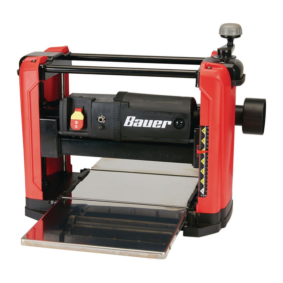
Related Manuals for Bauer 1621e-b


Summary of Contents for Bauer 1621e-b
- Page 1 Owner’s Manual & Safety Instructions Save This Manual Keep this manual for the safety warnings and precautions, assembly, operating, inspection, maintenance and cleaning procedures. Write the product’s serial number in the back of the manual near the assembly diagram (or month and year of purchase if product has no number). Keep this manual and the receipt in a safe and dry place for future reference.
-
Page 2: Table Of Contents
Table of contents Safety ............2 Maintenance ..........11 Specifications ..........5 Parts List and Diagram ......14 Setup ............6 Warranty ............ 16 Operation ............ 8 WARNING SyMBOLS AND DEFINITIONS This is the safety alert symbol. It is used to alert you to potential personal injury hazards. - Page 3 13. DON’T OVERREACH. Table A: REcOMMENDED MINIMUM WIRE GAUGE Keep proper footing and balance at all times. FOR EXTENSION cORDS (120 VOLT) 14. MAINTAIN TOOLS WITH CARE. Keep EXTENSION cORD tools sharp and clean for best and safest NAMEpLATE performance. Follow instructions for LENGTH AMpERES lubricating and changing accessories.
- Page 4 Grounding Instructions TO pREVENT ELEcTRIc SHOcK AND DEATH FROM INcORREcT GROUNDING WIRE cONNEcTION READ AND FOLLOW THESE INSTRUcTIONS: 110-120 VAc Grounded Tools: Tools with Three prong plugs 1. In the event of a malfunction or breakdown, 6. Repair or replace damaged or grounding provides a path of least resistance for worn cord immediately.
-
Page 5: Specifications
12. Stay alert, watch what you are doing and use 18. WARNING: Some dust created by power sanding, common sense when operating a power tool. sawing, grinding, drilling, and other construction Do not use a power tool while you are tired or activities, contains chemicals known to the State under the influence of drugs, alcohol or medication. -
Page 6: Setup
Setup - Before Use: Read the ENTIRE IMpORTANT SAFETy INFORMATION section at the beginning of this manual including all text under subheadings therein before set up or use of this product. TO pREVENT SERIOUS INJURy FROM AccIDENTAL OpERATION: Turn the power Switch of the tool off and unplug the tool from its electrical outlet before performing any procedure in this section. - Page 7 Assembly/Mounting cAUTION! Transport planer using carrying Handles only, do not lift with Rollers. Installing Dust chute Note: Dust Chute may be installed in Dust Wrench either left or right discharge direction. chute 1. Using included Wrench, attach Dust Chute to back of Planer with two Hex Screws. 2.
-
Page 8: Operation
Operating Instructions Read the ENTIRE IMpORTANT SAFETy INFORMATION section at the beginning of this manual including all text under subheadings therein before set up or use of this product. Tool Set Up TO pREVENT SERIOUS INJURy FROM AccIDENTAL OpERATION: Turn the power Switch of the tool off and unplug the tool from its electrical outlet before performing any procedure in this section. - Page 9 Workpiece and Work Area Set Up 1. Designate a work area that is clean and well-lit. 2. Route the power cord along a safe route to reach The work area must not allow access by children the work area without creating a tripping hazard or or pets to prevent distraction and injury.
- Page 10 Replacing Blades 1. Turn Planer off and unplug from its electrical outlet. 2. Using included Wrench, loosen Hex Screws on Dust Chute, then Remove two Hex Screws on Blade Guard. Remove Blade Guard. Blade Guard Screw Screw Wrench Magnets Figure H cAUTION! Blades are very sharp and are double-edged! Wear heavy-duty leather work gloves at all times when handling a blade.
-
Page 11: Maintenance
Maintenance and Servicing procedures not specifically explained in this manual must be performed only by a qualified technician. TO pREVENT SERIOUS INJURy FROM AccIDENTAL OpERATION: Turn the power Switch of the tool off and unplug the tool from its electrical outlet before performing any procedure in this section. - Page 12 Internal Maintenance Rods 1. Using allen wrench (not included), remove Hex Screws on Side Cover. 2. Remove Rubber Handle, Side Cover and Rods. Screw Screw Side cover Rubber Handle Lubrication 1. Elevation Screws and columns 2. Roller chains a. Remove both Side Covers. a.
-
Page 13: Troubleshooting
Troubleshooting Workpiece problem possible causes Likely Solutions Deeper cut at 1. Too little support of long boards. 1. Provide better support for long boards. ends of board 2. Uneven force on cutter head. 2. Level Tables according to Leveling (snipe). Table Extensions on page 8. -
Page 14: Parts List And Diagram
parts List and Diagram parts List part Description part Description Pan Head Screw Base Portable Sheath Bearing Left Cap Spacer Retainer Roller Pan Head Screw Plug Hex Screw 65.1 Spring Washer Right Cap Crank Arm 65.2 Flat Washer Handle Gear Handle Shaft Table Extension Assembly Knob... - Page 15 Assembly Diagram Item 63445 For technical questions, please call 1-888-866-5797. Page 15...
-
Page 16: Warranty
pLEASE READ THE FOLLOWING cAREFULLy THE MANUFACTURER AND/OR DISTRIBUTOR HAS PROVIDED THE PARTS LIST AND ASSEMBLY DIAGRAM IN THIS MANUAL AS A REFERENCE TOOL ONLY. NEITHER THE MANUFACTURER OR DISTRIBUTOR MAKES ANY REPRESENTATION OR WARRANTY OF ANY KIND TO THE BUYER THAT HE OR SHE IS QUALIFIED TO MAKE ANY REPAIRS TO THE PRODUCT, OR THAT HE OR SHE IS QUALIFIED TO REPLACE ANY PARTS OF THE PRODUCT.
Need help?
Do you have a question about the 1621e-b and is the answer not in the manual?
Questions and answers
My cutting head doesn’t move is there a lock I’m over looking
How do I purchase planer motor for 1621e-b 12 1/2 “ planer.
Is there such a thing as a main gear that runs a roller in a planer model 1621E-B?
I need a sprocket for my Bauer planer