
Related Manuals for McIntosh C200


Summary of Contents for McIntosh C200
- Page 1 Owner’s Manual C200 Preamplifier/Controller C200 McIntosh Laboratory, Inc. 2 Chambers Street Binghamton, New York 13903 2699 Phone: 607 723 3512 FAX: 607 724 0549...
-
Page 2: Important Safety Instructions
The lightning flash with arrowhead, The exclamation point within an equi- lateral triangle is intended to alert the within an equilateral triangle, is intended user to the presence of important to alert the user to the presence of uninsulated “dangerous voltage” within operating and maintenance (servic- the product’s enclosure that may be of ing) instructions in the literature ac-... - Page 3 Safety Instructions Thank You Please Take A Moment Care of Equipment: Serial Number: Purchase Date: Dealer Name: Technical Assistance Repair of Equipment: Customer Service ã...
-
Page 4: Operation
Inputs and send signals from the Balanced Outputs. You can also use Balanced and Unbalanced outputs simultaneously, connected to different power amplifiers. 7. A McIntosh Power Controller may be added to the C200 to Operation provide AC Power Switching to components that do not have Power Control Connections. - Page 5 Introduction and Performance Features Introduction · Precision Parts · Ultra Low Distortion Performance Features · Moving Coil and Moving Magnet Phono Input · Dual Chassis · Balanced and Unbalanced Inputs/Outputs · Multichannel Passthru Mode · Precision Tracking Volume Control · Full featured Remote Control ·...
- Page 6 Dimensions " 44.45cm " 6" Front View of the C200C 13.69cm 15.24cm 12 - " 31.12cm 17" 43.18cm " Rear View of the C200C 11.75cm 13 - " 33.65cm " 46.67cm 17" " 43.18cm 1.59cm " 3/16 Side View of the C200C "...
- Page 7 Dimensions " 44.45cm " 6" Front View of the C200P 13.69cm 15.24cm 12 - " 31.12cm 17" 43.18cm " Rear View of the C200P 11.75cm 13 - " 33.65cm " 46.67cm 17" 43.18cm " 3/16 Side View of the C200P "...
-
Page 8: Installation
Installation " 1/16 43.34cm C200C Front Panel " Custom Cabinet Cutout 12.38cm Cutout Opening for Custom Mounting Cabinet Front Panel C200C Side View in Custom Cabinet Cutout Opening for Ventilation Chassis Support Spacers " Shelf 2.54cm 14" " 35.56cm 17/32 C200C Bottom View "... - Page 9 Installation " 1/16 43.34cm C200P Front Panel " Custom Cabinet Cutout 12.38cm Cutout Opening for Custom Mounting Cabinet Front Panel C200P Side View in Custom Cabinet Cutout Opening for Ventilation Chassis Support Spacers " Shelf 2.54cm 14" " 35.56cm 17/32 C200P Bottom View 1.35cm "...
- Page 10 C200C to the C200P fuse size and rating ACCessory POWER CONTROL The EXTernal SENSOR Outputs send a turn-on signal to jack permits the connection McIntosh Source Component(s) of a McIntosh IR sensor for and/or Power Controller when the remote operation C200C is On...
- Page 11 C200P Rear Panel Switches and Connections AUX 1 accepts high level program MAIN Balanced source signals. PH 1 (MC) accepts low OUTPUTS contain level signals from a Moving Coil Phono Listen program Cartridge and PH 1 (MM) accepts sig- signals at all times nals from a Moving Magnet Phono Car- SPKR/AMP 1 and 2 tridge.
- Page 12 How to Connect the C200 Note: There is approximately a one half second delay in the turn on of the second Power Amplifier, so as not to tax the AC Power Line. McIntosh AM/FM Tuner Note: It is important to make sure that the two C200P...
- Page 13 How to Connect the C200 To AC Outlet Tape Deck Processor Turntable McIntosh Power Amplifier McIntosh Power Amplifier (Right Channel) (Left Channel)
- Page 14 How to Connect the C200 with Passthru Mode be mixed. For example, you may connect signal sources to Unbalanced Inputs and send signals out from the Balanced Outputs. You can also use Balanced and Unbalanced outputs simultaneously, connected to different power amplifiers.
- Page 15 How to Connect the C200 with Passthru Mode To AC Outlet Tape Deck Processor Turntable McIntosh Power Amplifier McIntosh Power Amplifier (Right Channel) (Left Channel)
- Page 16 C200P Front Panel Display and Connection HEADPHONE jack accepts dynamic headphones POWER ON indicator...
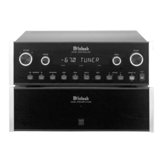
- Page 17 C200C Front Panel Controls, Displays, Push-Buttons, and Switches DISPLAY indicates the Listen and STANDBY/ON push-button LIS PROCESSOR Record Sources, Listening Volume turns the C200 On, or Off push-button turns the Listen Processor Level and Setup Functions (Standby) loop On or Off...
-
Page 18: Display Brightness
How to Operate the Setup Mode Display Brightness Figure 4 Figure 1 Text Display Options Note: The Front Panel Display will indicate DISPLAY 20 the first time, after then it will display what ever Setup Mode was last accessed. Figure 2 Figure 5 Figure 6 Figure 3... -
Page 19: Input Trim Level
Figure 9 Note: If all the Input Sources have been turned Off and the C200 is no longer in the Setup Mode, the Front Panel Display will Indicate NO SOURCE. Two Input Positions on the C200 have a Rear Panel Slide Switch associated with them. -
Page 20: Passthru Mode
Figure 15 Figure 13 Balance Control Rate-of-Change Volume Control Rate-of-Change Figure 16 Figure 17 Passthru Mode Figure 13 Figure 14... -
Page 21: Firmware Version
Setup, con’t Firmware Version Figure 18 Figure 22 Figure 19 Remote Control Selection Note: If the ALT Remote Control Code is selected, the C200 will not respond using the supplied McIntosh Remote Control. Figure 20 Figure 21... -
Page 22: Volume Control
How to Operate the C200 Power On Note: The POWER Switch is only intended to be switched Off when the C200 Controller/Preamplifier is not used for Source Selection extended periods of time, like while away on vacation. During normal operation, the POWER Switch should stay in the On Position. - Page 23 How to Operate the C200 Mono Setup Note: The C200 RECORD OUTPUTS are not affected by the VOLUME or BALANCE controls. To listen to a different program source while recording, turn the LISTEN switch to the desired source. The recording process will not be affected and will continue.
-
Page 24: Remote Control Push-Buttons
Turns power ON or OFF Tunes to the next to a component con- radio station nected via the Data Port Select dB or % Turns the C200 Volume Display ON or OFF Mode Adjusts the volume level up or down... -
Page 25: How To Operate The Remote Control
Disc and Track Optional Remote Control Tuner Functions Note: Non McIntosh Tuners may be controlled with the C200 Remote Control when they are connected together with a McIntosh RCT Translator. Refer to the RCT Owner’s Manual for further information on alternate Remote Control push button functions. -
Page 26: Specifications
Specifications Specifications Frequency Response Overall Dimensions Total Harmonic Distortion Weight Signal To Noise Ratio Maximum Voltage Output Output Impedance Sensitivity Input Impedance Maximum Input Signal Power Requirements Note: Refer to the rear panel of the C200C for the correct voltage. - Page 27 Packing Instructions Packing Instructions...
Need help?
Do you have a question about the C200 and is the answer not in the manual?
Questions and answers