
Related Manuals for Schleuniger EcoCut 3300

Summary of Contents for Schleuniger EcoCut 3300
- Page 1 EcoCut 3300 Automatic Cutting Machine Reference Manual Software Version 1.1x |Edition 4.0 (10-2013)
- Page 2 F +49 (0)21 959 29-105 P +86 (21) 62 52 66 77 info@schleuniger.de F +86 (21) 62 40 86 55 www.schleuniger.com sales@schleuniger.com.cn www.schleuniger.cn © 2013 Schleuniger EN | ID-0000000138-001 Part #: Order #: 2|108 Reference Manual |Edition 4.0 (10-2013) |EcoCut 3300...
-
Page 3: Table Of Contents
........... . . 3|108 Reference Manual |Edition 4.0 (10-2013) |EcoCut 3300... - Page 4 ..............4|108 Reference Manual |Edition 4.0 (10-2013) |EcoCut 3300...
- Page 5 ............5|108 Reference Manual |Edition 4.0 (10-2013) |EcoCut 3300...
- Page 6 ........... . 6|108 Reference Manual |Edition 4.0 (10-2013) |EcoCut 3300...
- Page 7 ........INDEX 7|108 Reference Manual |Edition 4.0 (10-2013) |EcoCut 3300...
- Page 8 Table of contents 8|108 Reference Manual |Edition 4.0 (10-2013) |EcoCut 3300...
-
Page 9: General
1. General GENERAL Thank you for your trust in the Schleuniger technique! You have acquired a high performance Schleuniger product, designed and manufactured in our factory to your needs. Read through this manual with due care and attention. It contains important tips and safety instructions, which allow precise and reliable wire/cable production. -
Page 10: Depository
Important activity direction, program- Referencing of text to picture elements in a ming example. previous figure. Topic: Disposal: Important safety relevant reference. Waste that must be recycled and not be disposed of with household waste. 10|108 Reference Manual |Edition 4.0 (10-2013) |EcoCut 3300... -
Page 11: Legend
Windows® (XP, Vista, 7 or CE) are registered trademarks of Microsoft Corporation in USA and other coun- tries. All other brands or product names are trademarks or registered trademarks of their owners. 11|108 Reference Manual |Edition 4.0 (10-2013) |EcoCut 3300... -
Page 12: Spare Parts
For further information, see chapter "14 Appendix (Page 77)". SPARE PARTS Always order original spare parts from your local Schleuniger distributor. Any modifications in design or function of the spare parts, in terms of ongoing product improvement, are subject to change without prior notification. -
Page 13: Safety
Only use original Schleuniger equipment, especially interface connection cables (electromagnetic ▄ compatibility). The product must always be operated through the Schleuniger emergency stop link unit, if it works ▄ together with peripheral devices in a production line. Only then can a safe interruption of the com- plete production line during an emergency be guaranteed. -
Page 14: Intended Usage Of Product
Caution, risk of injury, property damage! It is designed and manufactured exclusively for the following intended application: The EcoCut 3300 must be used only for cutting of cables, wires and tubes within the given range accord- ing to the technical specifications. -
Page 15: Safety Symbols On The Product
They have the ability to identify all sorts of danger and to avoid it. This includes an adequate knowledge of accident prevention and first aid procedures. Third party Externally called in personnel of the operating company, service technicians and staff from Schleuniger. 15|108 Reference Manual |Edition 4.0 (10-2013) |EcoCut 3300... -
Page 16: Eye Protection
The emergency stop buttons must always be accessible. ▄ Do not remove any safety barriers. ▄ Do not break in the emergency stop link between the machine and the peripheral devices. ▄ 16|108 Reference Manual |Edition 4.0 (10-2013) |EcoCut 3300... -
Page 17: Transport / Packaging / Storage
Before use of the product, remove, if present, any marked transport fixations. For later transportation store the transport fixations. PACKAGING The packaging 3.3.1 Store the packaging for later use on a weatherproof location. Handling packaging material 3.3.2 Recycle the unneeded packaging. 17|108 Reference Manual |Edition 4.0 (10-2013) |EcoCut 3300... -
Page 18: Internal Transportation
STORAGE Store the product under the following conditions: Not outdoor ▄ Observe temperature conditions ▄ Observe climatically conditions ▄ See also chapter "4.2 Technical specifications (Page 19)". 18|108 Reference Manual |Edition 4.0 (10-2013) |EcoCut 3300... -
Page 19: Product Specifications
Length (B) Height (C) TECHNICAL SPECIFICATIONS Description Value Unit Limit values Wire diameter Wire width Conductor cross section Stranded 16 (AWG 6) Solid 6 (AWG 10) Feed speed Pulling force Length resolution 19|108 Reference Manual |Edition 4.0 (10-2013) |EcoCut 3300... -
Page 20: Requirements On The Installation Location
Exit adapter for peripheral devices Synchronized postfeed interface External emergency stop button Pedal REQUIREMENTS ON THE INSTALLATION LOCATION Place on a solid, level work floor. The machine is designed for handling on table height. 20|108 Reference Manual |Edition 4.0 (10-2013) |EcoCut 3300... - Page 21 T3.15 A 230/240 VAC T1.6 A 50/60 Hz 120 VA Made in Switzerland 1 Machine type 4 Serial number 2 Permissible mains voltage 5 Mains frequency 3 Internal fuse protection 6 Power consumption 21|108 Reference Manual |Edition 4.0 (10-2013) |EcoCut 3300...
- Page 22 4. Product specifications 22|108 Reference Manual |Edition 4.0 (10-2013) |EcoCut 3300...
-
Page 23: Product Description
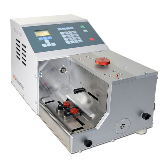
CONCEPT Der EcoCut 3300 is designed to automatically cut all kinds of material including wire, cable, round material such as tubing, flat ribbon and Glass Fiber Optic (GOF) cable. -
Page 24: 23 5.2.1 Operator Panel
5. Product description Operator panel 5.2.1 The operating software of the EcoCut 3300 is controlled via the operator panel. Gap setting wheel 5.2.2 The gap setting wheel is for adjusting the opening of the feed rollers to the processed material. For nor- mal material like stranded wires the gap setting is 0 mm (standard). -
Page 25: Postfeed Interface (Ppi, Option)
For the connection of a PC. Therewith wire programs can be saved and reloaded to/from an external memory in future. This connector is also used for software upgrades. HS/PF (HotStamp/Prefeeder) interface 5.3.3 To this connector a Hot stamp or a PreFeeder can be connected. 25|108 Reference Manual |Edition 4.0 (10-2013) |EcoCut 3300... -
Page 26: Pedal Connector
HotStamp 4140 ▄ HotStamp 4500 ▄ The EcoCut 3300 produces a marking pulse and interrupts the device during the marking time. For a detailed description of this interface, see chapter "14.2.2 For use with a HotStamp (Page 80)". For use with a PreFeeder The interface is optimized for the in chapter "14.2.1 For use with a PreFeeder (Page 79)"... -
Page 27: Safety Marking
Do not touch the wires during operation. Body parts or clothing can be catched and pulled into the ▄ wire entry. Do not grasp or look into the ejection area. The ejected wires may injure your hands and eyes. ▄ Fig. 4: Danger zones front 27|108 Reference Manual |Edition 4.0 (10-2013) |EcoCut 3300... -
Page 28: Danger Zones Rear
Turn off the main switch, block against switching on again and ▄ disconnect the machine from the mains (for hard wired machines, the main switch serves as a mains disconnecter unit). Unplug the machine from the air pressure supply. ▄ 28|108 Reference Manual |Edition 4.0 (10-2013) |EcoCut 3300... -
Page 29: Installation / First Commissioning
Place the machine on an even surface (Schleu- niger rack, table, work bench etc.). 4» Connect the power cord. 5» Connect the optional pedal. 6» Possibly connect the PC to the RS 232 connec- tor. 29|108 Reference Manual |Edition 4.0 (10-2013) |EcoCut 3300... -
Page 30: Setting The Measuring Unit And The Menu Language
6. Installation / first commissioning Setting the measuring unit and the menu language 6.3.2 1» Turn the main switch on the EcoCut 3300 on. [MENU] - Configuration User. 2» --> --> 3» Select the menu language / measuring unit with [@], [ENTER]. -
Page 31: General Handling / Operation
7. General handling / operation GENERAL HANDLING / OPERATION The operation of the EcoCut 3300 is described in this chapter in detail. GENERAL TOPICS FOR THE OPERATION operator personnel! The instructions in this chapter must be carried out by the Before the daily operation a visible check on the machine must be carried out. -
Page 32: Producing A Wire
Load a single wire or multiple wires, see above. 2» Select the desired wire program, see chapter "8.5.2 Load (Page 43)". Press [RUN]. 3» ➥ The wire will be produced according to the selected program. 32|108 Reference Manual |Edition 4.0 (10-2013) |EcoCut 3300... - Page 33 (4) is visible. 6» Loosen both head cap screws (4) of both col- lars and remove them. 7» Insert the new entry wire guides. 33|108 Reference Manual |Edition 4.0 (10-2013) |EcoCut 3300...
-
Page 34: Work To Be Done After Operation
Clean the processing area. ▄ After 1 week: Clean the housing and the processing area. ▄ Additional maintenance work 7.6.2 For further information, see chapter "11 Maintenance / maintenance schedule (Page 59)". 34|108 Reference Manual |Edition 4.0 (10-2013) |EcoCut 3300... -
Page 35: Operation Of The Control Software
Name of the loaded wire or "?" (wire not saved) "8.5 File menu (Page 43)" ▄ An "x" on the right corner indicates, that additional screens for the same level are available. ▄ 35|108 Reference Manual |Edition 4.0 (10-2013) |EcoCut 3300... -
Page 36: Keyboard
Performs a cutting procedure. Load /unload: No function. Start production: Starts the production of the programmed wire. Single wire: Produces a single wire with the programmed, current settings. Stop: Interrupts the production. 36|108 Reference Manual |Edition 4.0 (10-2013) |EcoCut 3300... -
Page 37: General
(x) on the right of the header line, between the same level. In certain screens the function key is used for the exe- cution of special functions. 37|108 Reference Manual |Edition 4.0 (10-2013) |EcoCut 3300... -
Page 38: Menu Structure
8. Operation of the control software Menu structure 8.2.1 The software of the EcoCut 3300 is structured in a main menu with 5 sub menus. Input area 8.2.2 There are two types of input areas, which make up two different screen types: Menu screen ▄... -
Page 39: Entry Fields
[DEL]. To toggle between upper and lower case can be done with [+/-]. MAIN MENU If the [MENU] key is pressed after switching on the machine, the main menu is shown on the display. 39|108 Reference Manual |Edition 4.0 (10-2013) |EcoCut 3300... -
Page 40: Wire Data 1
WIRE SCREENS Wire data 1 8.4.1 After switching on the EcoCut 3300 the user automati- cally accesses the screen „Wire“. The number of wires to produce (Total), the batch (@ batch / @ batch left) with batch size and the wire length is determined here. -
Page 41: Wire Marking
New correction factor = old correction factor x measured value The %-correction can be calculated by the EcoCut 3300. Enter the measured wire length (actual length) and press [+]. The calculated value is adopted to the %-cor- rection field, the measured wire length is reset to 0 and marked with an "x"... -
Page 42: Wire Stacker (Ppi, Option)
The EcoCut 3300 activates the output „Postfeed“ during the entered time. The ejection time depends on the duration of the stacking. Wait (ms) The EcoCut 3300 waits for the entered time, until the WS 500/1000 was moving to its home position. Sub- sequently the production continuous. Cable coiler (PPI, option) 8.4.5... -
Page 43: New
The screen can be left with without loading a ▄ Display of compatibility wire. Display of compatibility Symbol Meaning Saved and current wire data are identically. Saved and current wire data are identically. Total is different. 43|108 Reference Manual |Edition 4.0 (10-2013) |EcoCut 3300... -
Page 44: Save
With the key delete, the currently selected wire on the list is deleted, see chapter "8.5.2.3 Deleting a ▄ wire (Page 44)". The screen can be left with [×] without loading a wire. ▄ 44|108 Reference Manual |Edition 4.0 (10-2013) |EcoCut 3300... -
Page 45: Devices
Additional screens are activated accordingly. Combi on / no Combi With the operation of a wire marker device the wire feeding on the EcoCut 3300 is interrupted through the Combi input until the marking procedure is completed, see chapter "9 Operation using a marking device (Page 53)". - Page 46 Timeout usage This parameter switches the "Timeout-function" on/off. Timeout The EcoCut 3300 monitors, if a marking device is oper- ating or not after startup. If the marking device does not confirm the printing for any case, an error mes- sage will appear. The duration until an error message appears is called „Timeout“...
-
Page 47: User
All hints ▄ DIAGNOSTICS From the main menu the screen „Diagnosis“ can be reached with the key [4]. At the „Diagnosis“ screen all necessary diagnostics are made: Info ▄ Machine ▄ Peripheral ▄ 47|108 Reference Manual |Edition 4.0 (10-2013) |EcoCut 3300... -
Page 48: Info
4-2-3 modification of the "Info 999 wire end switch": 0: indicates a non active cable end switch (in upper ▄ position). 1: indicates an active cable end switch (in lower ▄ position). 48|108 Reference Manual |Edition 4.0 (10-2013) |EcoCut 3300... -
Page 49: Peripheral
1: indicates an active pedal (actuated). ▄ Wire marker Here the functioning of a connected marking device is tested. For this follow the instructions on the screen. 4-3-3 49|108 Reference Manual |Edition 4.0 (10-2013) |EcoCut 3300... -
Page 50: Password Restriction
8. Operation of the control software PPI (option) WARNING Danger if operated by unqualified personnel! The diagnostic on the PPI must only be carried out by Schleuniger personnel or a distributor. Here the functioning of an optional connected PPI is tested. 4-3-4 Preparation: 1»... -
Page 51: User Level Selection
Enter a new password and repeat the entry to confirm the password. In order to save the password, exit the screen with [OK]. Password on/off 8.8.3 This menu item is only shown with activated user level „Supervisor“. 51|108 Reference Manual |Edition 4.0 (10-2013) |EcoCut 3300... -
Page 52: Reset Password
Once the password is deactivated, all entries can be changed. ▄ The standard passwords must be changed and put aside. If a password gets ▄ lost, the passwords can be reset. This is reserved for the user level "Service". 52|108 Reference Manual |Edition 4.0 (10-2013) |EcoCut 3300... -
Page 53: Operation Using A Marking Device
To obtain a print in the middle of the wire, enter half the wire length in the „Right" position. ▄ If the entire typeface has shifted, the distance between marking device and the EcoCut 3300 has to be ▄ measured and reprogrammed. - Page 54 4» Press [CUT], to eject the marked wire. 5» Measure the distance from wire beginning to the right edge of the marking. 6» Enter the distance in the menu "Configuration - HotStamp". 54|108 Reference Manual |Edition 4.0 (10-2013) |EcoCut 3300...
-
Page 55: Diagnostics / Troubleshooting
The instructions in this chapter must be carried out by Behavior in case of an error 10.1.2 We advise the customer in case of a serious fault, to contact the local Schleuniger distributor, see "Page 2“. FAULT INDICATORS 10.2 Errors recognized by the software or the internal electronics show up on the display. - Page 56 Electronics on over temperature. The production is canceled. temporarily interrupted. Switch off the machine and wait for five minutes. Cutting motor could not brake. Motor control unit on error. Switch off and then on again the machine. 56|108 Reference Manual |Edition 4.0 (10-2013) |EcoCut 3300...
-
Page 57: Warnings
Prefeeder blocked! The prefeeder is not switched on or the wire entry area is blocked. Back to factory defaults! This resets all data to the factory setting. All wire programs are deleted. 57|108 Reference Manual |Edition 4.0 (10-2013) |EcoCut 3300... -
Page 58: Actions After Solving Errors
Appears with deletion of wire data. Delete without warning message. Do not delete. ACTIONS AFTER SOLVING ERRORS 10.6 To check the correct functioning of the machine before the series production, a functional check has to be performed. 58|108 Reference Manual |Edition 4.0 (10-2013) |EcoCut 3300... -
Page 59: Maintenance / Maintenance Schedule
If problems occur, which cannot be solved by the help of this manual, the Schleuniger distributor or the technical staff of Schleuniger is ready to assist you. In such situations it is essential to provide a precise description of the matter. -
Page 60: General
Dirt and talcum residues may affect the functioning of the machine. The machine has to be checked and necessarily be cleaned. WARNING Electric current! Before cleaning always switch off the main switch and unplug the product from the mains. Disregarding may lead to serious injury or death. 60|108 Reference Manual |Edition 4.0 (10-2013) |EcoCut 3300... -
Page 61: General Maintenance
WARNING Risk of injury! The blades mounted on this machine have razor sharp edges, which can cause serious injury if not handled properly during the blade change procedure. 61|108 Reference Manual |Edition 4.0 (10-2013) |EcoCut 3300... - Page 62 With this setting the blades can wear down faster. 62|108 Reference Manual |Edition 4.0 (10-2013) |EcoCut 3300...
-
Page 63: Configuring The Machine
If a fault condition occurs on the EcoCut 3300 always proceed first according to chapter "10 Diagnostics / troubleshooting (Page 55)". Not until a detailed labor trying to bring the EcoCut 3300 into operation again, the option of switching the whole machine back to their factory settings may be considered. NOTICE Caution property damage! The function "Factory default"... -
Page 64: Maintenance / Repair Work
Dan- gerous line voltage is present inside the machine and around the area of the mains socket, which can lead to serious injury or death if disregarding. 64|108 Reference Manual |Edition 4.0 (10-2013) |EcoCut 3300... -
Page 65: Opening The Housing
After the maintenance work has been done, swivel the housing to the front. 6» Tighten all screws (9 pcs). 7» Connect the machine to the mains and switch it on. 8» Perform a functional check. 65|108 Reference Manual |Edition 4.0 (10-2013) |EcoCut 3300... -
Page 66: Replacing Blades
Turn out the setting knob of the ejection chute (2). 3» Remove the ejection chute by loosening the four screws (3). 4» Disassemble the inner ejector plate (4) by loosening both screws (5). 66|108 Reference Manual |Edition 4.0 (10-2013) |EcoCut 3300... -
Page 67: Replacing Motors
16» Mount the adjustment handle of the ejection chute (2). 17» Mount the cover. Replacing motors 11.9.4 1» Open the cover of the machine, see chapter "11.9.2 Opening the housing (Page 65)". 67|108 Reference Manual |Edition 4.0 (10-2013) |EcoCut 3300... - Page 68 11» Press motor in the direction of the arrow to tension the belts. Tighten the screws. 12» Put the machine back to its normal position. 13» Connect the motor cables (1) and (2). 14» Close the housing of the machine. 68|108 Reference Manual |Edition 4.0 (10-2013) |EcoCut 3300...
-
Page 69: Replacing Belts
15» Screw on both motors with the screws (1) and (2) slightly. 16» Press motor in the direction of the arrow to tension the belts. Tighten the screws. 17» Close the housing of the machine. 69|108 Reference Manual |Edition 4.0 (10-2013) |EcoCut 3300... -
Page 70: Replacing Feed Rollers
"11.9.5 Replacing belts (Page 69)" 8» Remove the two screws of the gap setting wheel (5) and the two screws of the front plate (6). 9» Mount the lever of the feed rollers (7). 70|108 Reference Manual |Edition 4.0 (10-2013) |EcoCut 3300... - Page 71 23» Remove the screw (15). 24» Disassemble the roller lever assembly (16) from the unit. 25» Loosen the two screws on the holder (17). 26» Disassemble the drive roller. 71|108 Reference Manual |Edition 4.0 (10-2013) |EcoCut 3300...
- Page 72 37» Turn the machine to the side of the wire entry. 38» Screw on the motor loosely with both screws (3). 39» Slide motor in the direction of the arrow to tension the drive belt. Then tighten the screws. 72|108 Reference Manual |Edition 4.0 (10-2013) |EcoCut 3300...
-
Page 73: Exchanging Mains Fuses
Attach the fuse holder to the power supply module. 5» Connect the machine to the mains and switch it on. SPARE PARTS / EXPLODED VIEW DRAWINGS For original Schleuniger spare parts see „Parts Catalog“. 73|108 Reference Manual |Edition 4.0 (10-2013) |EcoCut 3300... - Page 74 12. Spare parts / exploded view drawings 74|108 Reference Manual |Edition 4.0 (10-2013) |EcoCut 3300...
-
Page 75: Decommissioning / Disposal
If equipped with air jet unit, switch off the compressed air supply and remove the hose. DISASSEMBLY / DISPOSAL 13.2 Disassemble the machine appropriately. Dispose of the disassembled parts according to the local legal requirements. Schleuniger machines mainly consist of the following materials: Material Disposal Aluminum Scrap metal... -
Page 76: Reference Manual |Edition 4.0 (10-2013) |Ecocut
13. Decommissioning / disposal 76|108 Reference Manual |Edition 4.0 (10-2013) |EcoCut 3300... -
Page 77: Appendix
14. Appendix APPENDIX SOFTWARE UPGRADE 14.1 Here we describe how the Software of the EcoCut 3300 is updated by means of the Schleuniger Software „Iguana“. What is necessary: EcoCut 3300 ▄ RS-232 wire (02:01 AM, receptacle (female) both sides) ▄... -
Page 78: Upgrade Procedure
Press the key [DATA EXCHANGE] (1). 5» If the EcoCut 3300 is connected to „Igua- na“ the first time, a dialog box appears where the machine serial number can be entered. 6» Enter the machine - serial number (2) without the year. -
Page 79: Connector Hs / Pf
14.2 For use with a PreFeeder 14.2.1 With Schleuniger PreFeeders the appropriate connection cable is delivered with the Prefeeder. As per the following diagram, the D-sub-connector can be self-wired by a qualified technician. 79|108 Reference Manual |Edition 4.0 (10-2013) |EcoCut 3300... -
Page 80: For Use With A Hotstamp
For use with a HotStamp 14.2.2 The Schleuniger HotStamp devices are shipped with their appropriate connection cable. As per the follow- ing diagram, the D-sub-connector can be self-wired by a qualified technician. 80|108 Reference Manual |Edition 4.0 (10-2013) |EcoCut 3300... - Page 81 Fig. 9: Connecting a PreFeeder Input „HSINPUT“, Pin 4 & 5: When operating a wire marker through this input, the wire feeding on the EcoCut 3300 is stopped until the marking process is terminated. Output „HSOUT“, Pin 1 & 2 The wire marker is operated through this output.
-
Page 82: Pre-/Postfeed Interface (Ppi, Option)
14. Appendix PRE-/POSTFEED INTERFACE (PPI, OPTION) 14.3 On the postfeed connector a Schleuniger CableCoiler or WireStacker or a customer specific device may be hooked up, see chapter "14.3.1.1 POSTFEED connector (Page 82)". NOTICE Caution, property damage! Basically the interface is protected against overload, short circuit, electrostatic discharge and electromagnetic interference. - Page 83 RENCA Impulse output for feed synchronization Output TIA/EIA-422 Electrical specifications of the connectors PNP inputs The PNP-inputs are internally protected against electro static discharge. The inputs are galvanically cou- pled to GND. 83|108 Reference Manual |Edition 4.0 (10-2013) |EcoCut 3300...
- Page 84 ≤ 10 µs IN_SRG NPN inputs The NPN inputs are internally protected against electrostatic discharge. The inputs are galvanically cou- pled to +24 V. Input Fig. 12: Principle schematic diagram of the NPN inputs 84|108 Reference Manual |Edition 4.0 (10-2013) |EcoCut 3300...
- Page 85 ) The sum of all the output currents of the PNP outputs must not exceed this value. b ) Switching threshold for the short circuit protection. The thermal protection may trigger early in cer- tain circumstances. 85|108 Reference Manual |Edition 4.0 (10-2013) |EcoCut 3300...
- Page 86 RS422). The signal behavior is based on the signals of an incremental encoder. The signals are provided directly from the motor control circuit in the machine. The impulse frequency is proportional to the feed rate of the EcoCut 3300. The feed direction (forward / backward) can be recognized by means of the signal phasing.
- Page 87 ) Short circuit against +24 V may lead to permanent damaging of the output circuitry. Wire processing machine LENCA / RENCA LENCA / RENCA LENCB / RENCB LENCB / RENCB Fig. 16: Signal sequence, wire transport direction forward 87|108 Reference Manual |Edition 4.0 (10-2013) |EcoCut 3300...
- Page 88 Fig. 17: Signal run, wire transport direction backward Supply outputs Synchronization signals are transmitted differentially according to standard ANSI TIA/EIA-422 (formerly known as RS422). Machine Fig. 18: Principle schematic diagram supply outputs 88|108 Reference Manual |Edition 4.0 (10-2013) |EcoCut 3300...
- Page 89 To avoid ground loops it is recommended that the signal on the peripheral device is galvanically decou- pled. This can be achieved through, e. g. relays or opto couplers (already available in most PLC‘s). In heavy EMV loaded areas, we recommend the use of shielded connections. 89|108 Reference Manual |Edition 4.0 (10-2013) |EcoCut 3300...
- Page 90 Fig. 20: Galvanically decoupled signals For transmission of synchronizing signals, the use of shielded cables is generally recommended. Peripheral device Signal converter Machine Galvanically isolated Shield Short distance Fig. 21: Synchronization signal transmission 90|108 Reference Manual |Edition 4.0 (10-2013) |EcoCut 3300...
-
Page 91: Block Diagram
14. Appendix BLOCK DIAGRAM 14.4 91|108 Reference Manual |Edition 4.0 (10-2013) |EcoCut 3300... - Page 92 Hazard pictograms Signal word No signal word. Hazard statements No known significant effects or critical hazards. Precautionary statements Prevention Not applicable. Response Not applicable. Storage Not applicable. Disposal Not applicable. Version 1/10 92|108 Reference Manual |Edition 4.0 (10-2013) |EcoCut 3300...
- Page 93 Get medical attention if symptoms occur. Protection of first-aiders : No action shall be taken involving any personal risk or without suitable training. Version 2/10 93|108 Reference Manual |Edition 4.0 (10-2013) |EcoCut 3300...
- Page 94 Avoid dispersal of spilt material and runoff and contact with soil, waterways, drains and sewers. Inform the relevant authorities if the product has caused environmental precautions pollution (sewers, waterways, soil or air). 6.3 Methods and materials for containment and cleaning up Version 3/10 94|108 Reference Manual |Edition 4.0 (10-2013) |EcoCut 3300...
- Page 95 Derived effect levels No DELs available. Predicted effect concentrations No PECs available. Version 4/10 95|108 Reference Manual |Edition 4.0 (10-2013) |EcoCut 3300...
- Page 96 Vapour pressure Not available. Density : 0.95 g/cm [20°C] Bulk Density : Not available. Solubility(ies) Insoluble in the following materials: cold water. Partition coefficient: n- Not available. octanol/water Version 5/10 96|108 Reference Manual |Edition 4.0 (10-2013) |EcoCut 3300...
- Page 97 Carcinogenicity Conclusion/Summary : Not available. Reproductive toxicity Conclusion/Summary : Not available. Teratogenicity Conclusion/Summary : Not available. Specific target organ toxicity (single exposure) Not available. Specific target organ toxicity (repeated exposure) Version 6/10 97|108 Reference Manual |Edition 4.0 (10-2013) |EcoCut 3300...
- Page 98 Acute LC50 1000 to 5000 mg/l Fish 96 hours Chronic NOEC >5000 mg/l Fish 96 hours Conclusion/Summary : Not available. 12.2 Persistence and degradability Conclusion/Summary : Not available. 12.3 Bioaccumulative potential Not available. Version 7/10 98|108 Reference Manual |Edition 4.0 (10-2013) |EcoCut 3300...
- Page 99 Not regulated. 14.2 UN proper shipping name 14.3 Transport hazard class(es) 14.4 Packing group 14.5 Environmental hazards 14.6 Special Not available. Not available. Not available. precautions for user Additional information Version 8/10 99|108 Reference Manual |Edition 4.0 (10-2013) |EcoCut 3300...
- Page 100 Full text of abbreviated H H412 Harmful to aquatic life with long lasting effects. statements Full text of classifications Aquatic Chronic 3, H412 AQUATIC TOXICITY (CHRONIC) - Category 3 [CLP/GHS] Version 9/10 100|108 Reference Manual |Edition 4.0 (10-2013) |EcoCut 3300...
- Page 101 The data provided are intended to describe the product in relation to the required safety measures; they are neither an assurance of characteristics nor a guarantee of the product's suitability for particular applications and do not justify any contractual legal relationships. Version 10/10 101|108 Reference Manual |Edition 4.0 (10-2013) |EcoCut 3300...
- Page 102 14. Appendix 102|108 Reference Manual |Edition 4.0 (10-2013) |EcoCut 3300...
- Page 103 ..................103|108 Reference Manual |Edition 4.0 (10-2013) |EcoCut 3300...
- Page 104 ..................104|108 Reference Manual |Edition 4.0 (10-2013) |EcoCut 3300...
-
Page 105: Index
Marking time 26 Emergency stop link 16 Measures 11, 19 Entry keys 35 Measuring unit 30, 47 Entry screen 38 Menu level 10 Errors 59 Menu screen 38 Motor switched off 57 105|108 Reference Manual |Edition 4.0 (10-2013) |EcoCut 3300... - Page 106 Wire end switch 48 Regular inspection 55 Wire entry guide 23 RS 232 25 Wire feeding 81 Wire marker 81 Wire type 59 Safety barrier 16 Wire/cable guide 60 Safety cover 16 106|108 Reference Manual |Edition 4.0 (10-2013) |EcoCut 3300...
Need help?
Do you have a question about the EcoCut 3300 and is the answer not in the manual?
Questions and answers