Table of Contents
Advertisement
Quick Links
Mounting instruction for
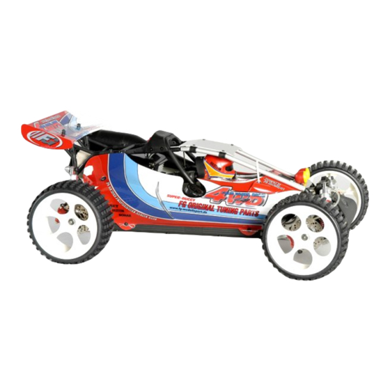
Competition 4WD Off-Road 1:6 Baja Buggy
Item No 66000, 66001
We congratulate you on buying this FG Competition model. Please check the contents of
the construction set, respectively of the bags. The individual bags had been thoroughly
packed by us and their weight and content had been checked. When purchasing the indivi-
dual bags, please check their weight and their closure by staples which must not have
been removed or opened and closed several times. It is possible that the weight of an indi-
vidual bag deviates by 5 grams. In case of claims due to missing parts, you always need to
present the label indicating the weight at your specialized dealer. By checking the weight of
the bag, you may exclude that larger parts or several parts are missing.
Weight of the individual bags/boxes:
Item No 66000, 66001
Bag A
= 1 part
Bag B
= 0.771 kg
Bag C
= 0.931 kg
Bag D
= 1.085 kg,
Bag E
= 0.407 kg
Bag F
= 0.900 kg
Bag G
= 0.191 kg
Bag H
= 0.383 kg
Bag I1
= 0.490 kg, only for 66000
Bag I2
= 0.499 kg, only for 66001
Bag J
= 0.117 kg
Bag K
= 0.343 kg
Bag L
= 0.343 kg
Bag M
= 0.285 kg
Bag N1 = 0.027 kg, only for 66000
Bag N2 = 0.038 kg, only for 66001
Bag O
= 0.299 kg
Bag P
= 0.239 kg
Bag Q
= 0.604 kg
Bag R
= 0.397 kg
The RCS accumulators and battery charger are not included in the
delivery volume.
Please thoroughly keep this construction instruction for spare parts' orders!
Are you interested in receiving 4WD news?
For example information about meetings,
races, technical hints. Just send us an email
with your name and email address to
marketing@fg-modellsport.de. You will receive
the 4WD news automatically when available.
FG Modellsport-Vertriebs-GmbH
Spanningerstr. 2
73650 Winterbach-Germany
Phone: +49 7181 9677-0
Fax: +49 7181 9677-20
info@fg-modellsport.de
www.fg-modellsport.de
E.66000-66001-271008
Advertisement
Table of Contents

Related Manuals for FG Modellsport 66000


Summary of Contents for FG Modellsport 66000
- Page 1 = 0.343 kg Bag M = 0.285 kg races, technical hints. Just send us an email Bag N1 = 0.027 kg, only for 66000 with your name and email address to Bag N2 = 0.038 kg, only for 66001 Bag O = 0.299 kg...
- Page 2 The handling with fuels requires circumspective and careful hand- Comments regarding the construction manual: ling. Imperatively observe the security advices. Before starting the assembly please see through this construction manual. This way you will get an overview of the whole execution. -Refuel only if the engine is switched off! Please check by means of the parts or bag list if the construction kit is -Take off the body.
- Page 3 All metric screws need to be secured with thread lock fluid. Position 1 Diff. gearwheel B Ball diff. Parts are in driving axle bag B Ball bearing 15x28x7 Diff. gearwheel A Shim ring 8x20x0.1 Shim ring Bronze 5x17x0.1 bush Needle Steel gearwheel bearing f.
- Page 4 1. Push the front differential gear, deflection roller 16mm, toothed belt Position 3 wheel 12 teeth in the left alloy front axle housing as described in Parts are in Left position 3. front axle bag C housing 2. Put the toothed belt on the front differential gear, deflection roller 16mm and the toothed belt wheel with 12 teeth as described in posi- tion 3.
- Page 5 1. Push the bearing shaft for the stretching pulley housing centrically in Screw Position 7 the 3 ball bearings 10x19x7. M4x14 Parts are in 2. Push the plastic bearing seat with inbound collar in the left and right bag B Toothed belt stretching pulley housing as described in position 7.
- Page 6 Position 9 Parts are in bag D Stabilizer Alloy connection brace Screw M4x20 Disk Ø4.3 Rear axle cover Screw M5x25 Taper disk Hexagon nut M8 right-handed thread Stop nut Adjusting screw Taper disk r/l 32mm Stop nut Screw Disk Ø4.3 Alloy ball- M3x16 and- socket...
- Page 7 1. Mount the rear alloy shock mount to the left and right alloy rear axle Position 11 mount using the M4x20 pan-head screws. Parts are in 2. Push the stabilizer in the rear alloy shock mount and fasten it using bag D Rear alloy shock mount...
- Page 8 1. Push the guide bushes with collar in the rear Position 14 upper alloy wishbones. Parts are in 2. Screw the hexagon nuts with M10 left-handed thread bag D on the rear wishbone thread rods M10/M8 and screw it in the rear upper alloy wishbones, then screw the hexa- gon nuts with M8 right-handed thread and alloy ball-and-socket joints on the rear wishbone thread rods M10/M8.
- Page 9 1. Insert 2 red silicone O-rings each in the alloy shock absorber hou- Internal Position 16 Internal silicone sing as described in position 17. silicone Parts are in tube Ø4 tube Ø5 2. Insert the black O-rings in adjustable rings and screw the adjustable bag E rings on the alloy shock absorber housing.
- Page 10 Screw Position 19 M4x14 Guide for Parts are in stabilizer bag F Guide bush with collar Front lower Front lower wishbone pin alloy wishbone Screw Guide for M4x14 stabilizer Front stabilizer Ball- type Headless Screw nipple M3x6 M5x20 Screw Plastic brace for M4x12 stabilizer Position 20...
- Page 11 1. Push the guide bushes in the front upper alloy Position 22 wishbones. Parts are in 2. Screw the hexagon nuts M10 with left-handed bag F thread on the front wishbone thread rods M10/M8 and screw it in the front upper alloy wishbones, then screw the hexagon nuts M8 with right-handed thre- ad and alloy ball-and-socket joints on the front wish- bone thread rods M10/M8.
- Page 12 1. Mount the shock mount to the reinforcing plate for Stop nut Screw Position 24 the front axle using M4x16 countersunk screws, M4x16 Disk Parts are in Ø4.3 disks Ø4.3 and M4 stop nuts. bag G Screw M4x10 2. Mount the plastic fixing plate with brake guide rail and alloy distances between the brake guide rail and Reinforcing plate Disk...
- Page 13 1. Remove the recessed head screw from the cover of the engine hou- Position 27 sing and cut off the front part of the cover. Parts are in Motor 2. Mount the long and short steel fixing plate to the large alloy engine bag H mount using M4x14 pan-head screws, then mount the alloy engine mount to the coupling flange using a M6x10 pan-head screw.
- Page 14 Position 29 Parts are in Filter cover bag J Screw 4,2x13 Basic Air filter body Motor adapter O-ring for air filter adapter Screw 4,2x16 Foam filter Gearwheel Manifold cover gear Alloy engine Screw mount large M4x10 Disk Silencer Ø4.3 gasket Screw M5x16 Position 30...
- Page 15 Before you start mounting of the remote control components, ple- ase also thoroughly read the enclosed RC manual and deal with the transmitter, receiver and the servos. Charge the receiver and transmitter batteries to full charging level and check if they are working properly.
- Page 16 For the receiver/servo current supply, we recom- Position 35 Item No mend to use the FG Mini-Racing pack item No Parts are in 06547/02 06543/01 due to the constricted space conditions. bag L Additionally, there is also required the FG receiver cable 06547/02.
- Page 17 1. Mount the servo saver spring to the alloy servo saver A, then push the flange sleeve for the alloy servo saver in the alloy servo saver A. Position 37 Servo saver 2. Push the guide bush 7x10x14 in the alloy servo saver B, until both Parts are in axle bag L...
- Page 18 Position 41 Parts are in Manifold bag M,O Exhaust hose Screw 4.2x25 Hose clamp Alloy rear shock mount 3-unit tuning pipe Screw Roll 4.2x22 cage Spoiler mount Headless Plastic brace short M5x25 Plastic brace Throttle rods long Screw Screw Spark plug M4x14 4.2x22 Rear body...
- Page 19 1. Press the exhaust hose with the hose clamps on the 3-unit tuning Position 44 Plastic com- pipe, then push it with the free end on the manifold. Parts are in ponent for 2. Screw M5x25 headless pins halfway through in the spoiler mounts the bags M,O 3-unit tuning stiffening...
- Page 20 The position 46-52 shows the Competition 4WD Off-Road 1:6 Baja Buggy item No 66001 with a mechanical brake system. In order to mount the tuning disk brake, please Position 46 Front right disk brake refer to the descriptions in the enclosed Parts are in manual.
- Page 21 Alloy bow- Bowden den cable cable holder long Rear left disk brake Position 50 Rear right disk Parts are in brake Brake disk bag R Brake shaft Screw 3x10 Stop Position 49 Guiding plate Parts are in Competition Stud bolt bag R brake lining Bowden cable...
- Page 22 The position 53-59 shows the Competition 4WD 1:6 Baja Buggy Item No 66000 with the hydraulic FG-Magura brake system. All metric screws need to be secured with thread lock fluid. Position 53 1. Mount 1 angle connection and 1 valve each for each main brake Parts are in cylinder as described in position 54 and 58.
- Page 23 Position 56 Parts are in bag Q 5. Then install the servo rods with pressure spring and collets as des- cribed in position 54 and 58. Left side in direction of motion for the rear brake, right side for the front brake. The servo rods needs to be Brake disk bent off towards the main brake cylinder according to the mounting height and size of the servo.
- Page 24 Plastic component Position 60 Drill with diameter for stiffening brace Parts are in of 2.5mm. bag P Plastic fixing plate Screw M4x8 Side guard Alloy cover Screw Body M4x8 Plastic brace for clamp cover Body clamp Alloyplate front Screw 2.9x9.5 Screw 2.9x9.5 Alloy brace long...
- Page 26 Exploded diagram for FG Baja Buggy Competition 4WD/ 1:6 Item No 66000, 66001 66291/3 66292/3 66292/2 66291/2 6738/3 7088 6734/3 6484/1 6481/6 6481/5 Rear spoiler 06421/05 6484/5 Decal 66155 66303 6481/3 6481/4 rear 66305 front 7091/2 6481/1 6092 7093 Body Baja-Buggy 4WD...
- Page 27 6912/13 6912/16 6926/16 6402/1 66218/1 7384 7119 6291/3 7332 6464/4 6451/3 6451/4 6465/1 6292/2 6294/1 6291/3 6912/13 6930/5 6920/14 6038 6738/5 6485/1 6930/5 6723/16 6928/3 6925/10 66217 8345 6020 6930/5 6734/4 6726/40 6925/30 66211 6734/4 66246 6927/10 7318 7315 6036/5 6738/3 6037/1 7316...
Need help?
Do you have a question about the 66000 and is the answer not in the manual?
Questions and answers