Table of Contents
Advertisement
Advertisement
Table of Contents

Subscribe to Our Youtube Channel
Related Manuals for L.T. Rich Products Z-Spray

Summary of Contents for L.T. Rich Products Z-Spray
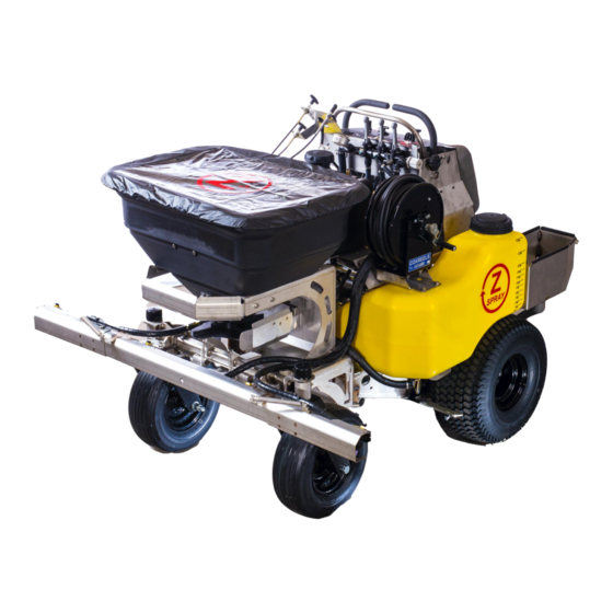
- Page 1 OWNERS MANUAL Z-Spray (60 Gallon Z-Max / 30 Gallon Intermediate/Junior)
-
Page 3: Table Of Contents
TABLE OF CONTENTS SECTION 1 TO THE OWNER PAGE Read this manual entirely BEFORE operating the Z-Spray………………………..…..1 Product / Warranty Registration…………….…………………………………..……...1 L T Rich Products Warranty……………………………………………………………1 Component Manufactures’ Warranties…………………………………………..……..2 Conditions Which Void Warranty……………………………………………….……..2 Warranty Exceptions……………………………………………………………..……..2 SECTION 2 SAFETY INFORMATION PAGE About this manual………………………………………………………………...….2-3... - Page 4 12 months. Any exceptions to this will be explicitly stated in an individual warrant agreement in the operator’s manual of that piece of equipment. Not having this registration card in our database will VOID any warranty filed* Fax to: 765-680-0047 or email to sbell@z-spray.com...
-
Page 5: Read This Manual Entirely Before Operating The Z-Spray
TO THE OWNER Read this manual entirely BEFORE operating the Z-Spray The information presented herein will prepare you to operate the L.T. Rich Z-Spray in a safe and knowledgeable manner. Operating the Z-Spray in a proper manner will provide a safer working environment, create more efficient results and promote higher quality. -
Page 6: Component Manufactures' Warranties
Z-Spray. The designed and tested safety of the Z-Spray is dependent upon its operations within the parameters and limitations explained in this manual. Be familiar with and follow all safety rules in this manual as well all safety rules for any related equipment. -
Page 7: Safety Guards And Covers
Never operate the Z-Spray without all covers, shields, and safety devices installed and secured. Never permit any person other than the operator to ride or board the Z-Spray at any time. NEVER ALLOW RIDERS!!! Use extreme care and maintain minimum ground speed when transporting on a hillside or over rough ground, and when operating close to ditches, fences, or water. -
Page 8: Storage Safety Rules
**use fuel stabilizer if machine will sit for more than 30 days** Never store the Z-Spray in any area accessible by children. Never store the Z-Spray with fuel in the tank inside a building where fumes could reach an open flame or spark. -
Page 9: Hydraulic System Maintenance
Oil Recommendations: Briggs & Stratton recommends the use of certified oils for best performance. Other high-quality detergent oil are acceptable if classified for service SF, SG, SH, SJ or higher. Do not use special additives. Outdoor temperatures determine the proper oil viscosity for the engine. Use the chart to select the best viscosity for the outdoor temperature range expected. -
Page 10: Traction System Maintenance
(depending on your water source, not draining the water out of the system and storing the Z-Spray dry can create algae build up). -
Page 11: Spreader System Maintenance
Attachment Maintenance The Z-Spray can be equipped with a few of the L T Rich Products attachments. These available attachments include an 7 gallon auxiliary tank, 30 gallon specialty tank, Isolated Tank or a 1 gallon Foam Marking Kit. -
Page 12: Overview
This attachment is used mostly for your NON-TURF friendly products such as Round Up and other total kill products, but can also be used for selective products. ~ Foam Marking Kit (part # 80907-60 or 80930-Foam) – This attachment allows a unit to mark the turf and make the operator aware of where the product was just applied. -
Page 13: Operation
~Spreader – The Z-Spray units are equipped with a 220 lb. or 120 lb. spreader. The hydraulic hopper motor with the spreader control rate knob allows variable spread widths from 3 to 25 feet. -
Page 14: Spray/Spreader System Page
Using the spreader system, there are 3 cables to operate the hopper door (far left cable), the diffuser (middle cable) and the deflector shield (lower right cable). By pulling on the far left hopper door cable, this will open the door and allow product to fall on the spinner. Adjustments as to how wide the door opens are made on the front on the hopper with the Hopper Rate Dial (Ref # 37 on page 17). -
Page 15: Spray Calibration/Tip Chart/Liquid Quantities
(Hose reel Chrome Valve in open position) Spray Calibration/Tip Chart/Liquid Quantities The Z-Spray liquid system comes standard with lavender colored Air Injected tips which will apply liquid material @ .34 (1/3) gallons per 1,000 sq. ft. @ 5 mph and 40 psi. Each tip has a 5 psi shut-off screen to prevent drip. -
Page 16: Spreader Calibration/Layout
Your machine is capable of using tips from ¼ to 1 gallon in size. See chart for your desired drop rate. The following are some general guidelines for sprayer calibration (Note: this chart only applies if using Air Injected tips. Using other tips will require different calculations). Please refer to the spray chart provided for complete calibration (spray charts are now located on the backside of the knee pad for quick in the field reference). - Page 17 (Hopper, Diffuser and Deflector Cables) (Hydraulic hopper motor) (Hopper Rate Dial) (Diffuser shown on underside of opening) Your machine is equipped with a 220 lb. or 120 lb. Spyker model spreader. The hydraulic spreader motor with the spreader motor control has the ability to vary spread widths from 3 to 25 feet.
-
Page 18: Part Numbers / Pictorial
SECTION 6 PARTS Part Number / Pictorial Wheel Parts (front and rear) Part # Description Front 16” Wheel Assembly 80019-A 80019-B Front Wheel Spacers 80309 Front Wheel Cone Bearings 80311 Front Wheel Bearing Cup (for replacement only) 80021 Rear Wheel Assembly for Max & Inter. (not pictured) 80020 Rear Wheel Assembly for Junior (not pictured) 80310... - Page 19 Hydraulic Parts/Idler Bracket Parts Part # Description 80003-Premium Idler Pulley 82020-A Idler Pulley Bracket Weldment 80304 Idler Pulley Bracket Bushings 80112 Idler Spring 80413-B44 Drive Belt (B44) HHESC5-12221 Idler Bracket Bolt FW-SAE-12 Idler Bracket Washer NNC-12 Idler Bracket Nylon Nut 80459-REVBB Tandem Pumps TL-TBBA-FBBB-6XHL 80402-15L...
- Page 20 Spot Spray Gun Part # Description 60040 1 ea Spot Spray Gun 60041 1 ea Spot Spray Tip ¼” MPT X 3/8” Barb 60029 1 ea Page 16...
- Page 21 120 lb & 220 lb Hopper Parts Page 17...
- Page 22 Page 18...
- Page 23 Z-Max/Intermediate/Junior Manifold Assembly Page 19...
- Page 24 Z-Max/Intermediate/Junior Liquid Valve Assembly Page 20...
- Page 25 Intermediate/Junior Boom Assembly Page 21...
- Page 26 Z-Max Boom Assembly Page 22...
-
Page 27: Parts List
Parts List 30675 JOY STICK GRIP 30676 BRAKE HANDLE GRIP 60009 1/4" CHROME VALVE\n90FMB14 60010 DIRECTO VALVE AA6B 60017 3/4'MPT X 3/4'FPT 90 ST EL\n3SE34 60020 3/4' MPT CLOSE NIPPLE\n3M34 60026 3/4'MPT X 1/2' HB 90\n3EL3412 60029 1/4' MPT TO 3/8' BARB \n3A 1438 60040 SPOT SPRAY GUN 60041... - Page 28 30712 STRAINER CAP DECAL 80302 CASTER BEARING SEAL\nSL-122 70023-E 12" 220 NEW HOPPER SHAFT 60106 COX HOSE REEL 80411-15 15mm Hydro Pulley New Style 86006 220 Hopper Hose 6.875 ZMAX/INT 60027 1/2'MPT X 1/2' HB 90\n3EL12 80112 BOOM SPRING/BELT TENSION 30678 SPEED BAR KNOB 80064...
- Page 29 30677-Sprayer 30706 SERIAL NUMBER DECAL 80461-HOSE 11" ENGINE OIL DRAIN HOSE HZ200BLK-08-18 1/2" X 18" BOOM HOSE 80313 MTE HOPPER MOTOR CAP LTR60GALHYDDN 18" HYDRO DRAIN HOSE 60130-LEFT 30 GALLON ZMAX TANK LEFT 60130-RIGHT 30 GALLON ZMAX TANK RIGHT 60130-15L 15 GALLON INTERMEDIATE/JUNIOR TANK LEFT 60130-15R 15 GALLON INTERMEDIATE/JUNIOR TANK RIGHT...
- Page 30 80527 EXHAUST CLAMP\nU125 ZINC 80421 3/8' 90 DEG HYDRO PUMP FITTING(6)\n6801-06-06-4 80205-2014+ 2014+ Ignition Harness GCP3JCFXJCFX90080808- 42" 1/2 JICX JIC 90 HZ200BLK-08x500 GOODYEAR HORIZON 1/2' 200 WP BLACK RLS 30404 60 Gal. Footplate Vibration Isolator LTBC-33R 33" RED BATTERY CABLE 90001 100B3X1/8 TRIM-LOK EDGING 80413-B44...
-
Page 31: Troubleshooting
SECTION 7 TROUBLE SHOOTING Troubleshooting Engine: Not starting. There are a few reasons as to why your engine fails to start. If the engine does not turn over, then the battery could be dead, bad connection to the battery wires, key switch may be bad, 30 AMP fuse on the wiring harness (orange wire) may be blown or the starter solenoid may be bad (you will hear the starter solenoid trying to click on, but nothing is happening). - Page 32 Granular: There are numerous potential challenges that can happen on the granular side due to the amount of use this portion of the unit sees. If product is not spreading evenly or consistently, then look for a few things with your hopper impeller or hopper diffuser.
- Page 33 Charging Issues: 20 Amp Regulated Alternator The 20 amp regulated alternator system provides AC current through two output leads to the regulator-rectifier. The regulator-rectifier converts the AC current to DC, and regulates current to the battery. The charging rate will vary with engine RPM and temperature.
- Page 34 DC Output Charging Wire Test A simple test can be used to test the DC output charging wire circuit. If a wiring problem exists it can be corrected before testing regulator-rectifier. Leave stator wire harness disconnected from regulator-rectifier. Equipment key switch must be in OFF position.
- Page 35 Wiring Harness Page 31...
-
Page 36: Maintenance Chart
Maintenance Chart Daily Weekly Bi-Weekly Monthly Yearly Hours SERVICE ACTION(S) Front Caster Wheels (grease) Front Caster Yokes (grease) Front Tire Pressure (22 PSI) Front Tire Bearing “preload” Rear Tire Pressure (18 PSI) Rear Rim Nut Torque (75lbs) Rear Hub Castle Nut (check cotter pin) Frame to base hardware Idler Pulley Arm...
Need help?
Do you have a question about the Z-Spray and is the answer not in the manual?
Questions and answers
My propeller speed is turning real slow and won’t increase speed when I turn the knob. The knob wasn’t turning at first and I stayed WD 40 on the cable. The knob was not at first turning but eventually did, but the speed didn’t increase. Did I break something?
Message is above.
A slow propeller speed that does not increase when adjusting the knob on an L.T. Rich Products Z-Spray could be caused by air in the hydraulic system, a loose impeller, or issues with the hydraulic hopper motor.
This answer is automatically generated