
Related Manuals for Gree CONSO9HP230V1AF


Summary of Contents for Gree CONSO9HP230V1AF
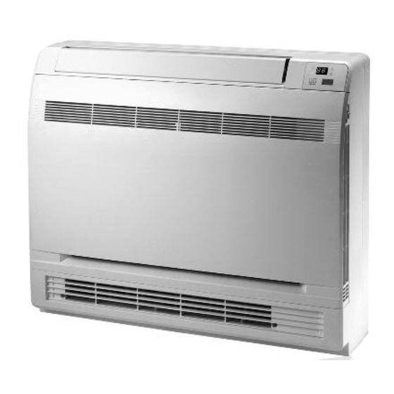
- Page 1 MINI-FLOOR CONSOLE INSTALLATION MANUAL Models: CONSO9HP230V1AF CONS12HP230V1AF CONS18HP230V1AF...
-
Page 2: Table Of Contents
Thank you for choosing a Multi21 Mini Floor Console Ductless Heat Pump System for your customer. Please read this installation manual carefully before installing and starting up the Floor Console Ductless System. Take a moment to fill out the product and installation form on the back cover. -
Page 3: Safety Precautions
SAFETY PRECAUTIONS Please read the following before installation. This is the safety alert symbol. It is used to alert you to potential personal injury hazards. Obey all safety messages that follow this symbol to avoid possible injury or death. This mark indicates procedures which, if improperly performed, W RNING might lead to the death or serious injury of the user. -
Page 4: Nomenclature
Example: CONS18HP230V1AF CONS 18 HP 230V 1 NOMENCLATURE Product Type Series Designation S - System O - Outdoor units CONS - Floor Console H - Indoor High Wall D - Indoor Duct C - Indoor Cassette F - Indoor Floor/Ceiling Cooling Capacity 9 - 9,000 BTUH 12 - 12,000 BTUH... -
Page 5: Suggested Tools
SUGGESTED TOOLS • Standard Wrench • Adjustable/Crescent Wrench • Torque Wrench • Hex Keys or Allen Wrenches • Drill & Drill Bits • Hole Saw • Pipe Cutter • Screw drivers (Phillips & Flat blade) • Manifold and Gauges • Level •... -
Page 6: System Parts
SYSTEM PARTS Indoor Unit Part Name 1. Front Cabinet 2. Remote Controller 3. Front Panel 4. Service Cover 5. Liquid Pipe 6. Gas Pipe 7. Drain Pipe Outdoor Unit 5 6 7 C UTION The refrigerant pipe, drain pipe and electrical wiring for this unit should be installed by a qualified HVAC professional only. -
Page 7: Installation Site Instructions
INSTALLATION SITE INSTRUCTIONS Indoor Unit W RNING The unit must be installed in a location which can withstand four times the weight of the unit. Inadequate support may result in serious property damage and injuries. Select a site that allows for the following: Ensure the installation complies with the installation minimum dimensions and meets the •... -
Page 8: Indoor Unit Installation
INDOOR UNIT INSTALLATION Indoor Unit Dimensions INDOOR UNIT DIMENSIONS Inches (mm) 27.6 (700) 8.5 (215) 23.6 (600) Preparing Indoor Unit for Installation Begin the mini-floor console indoor unit installation by removing the front panel and cabinet section to gain access to the unit mounting holes. 1. - Page 9 INDOOR UNIT INSTALLATION Preparing Indoor Unit for Installation Remove the front cabinet from the unit casing. Refer to figure below. 1. Locate and remove 4 mounting screws. 2. Disengage 3 locking tab on top and 2 on the bottom of front cabinet and gently separate from unit casing.
-
Page 10: Indoor Unit Installation
INDOOR UNIT INSTALLATION Laying Out Indoor Location 1. Determine the mounting location on the wall for the indoor unit. Follow the selection criteria in the previous section. 2. Locate the factory supplied installation template included in carton and attach to the wall. Verify the installation template is level right to left. -
Page 11: Piping Installation
PIPING INSTALLATION Drill Hole in Wall 1. Carefully remove indoor unit from wall mounting hooks. 2. Cut the wall hole with a 5° to 10° downward slant to the outdoors. See Wall Hole Size table below. Indoor Outdoor Wall Hole Sleeve Unit Size Wall Hole Size Seal Hole... - Page 12 PIPING INSTALLATION Refrigerant Piping Piping Preparation 1. Do not open service valves or remove protective caps on pipes until instructed by this manual. 2. Keep tubing free of dirt, sand, moisture and contaminants. 3. Insulate each refrigerant pipe and condensate hose with minimum 3/8” (10 mm) wall thermal pipe insulation.
- Page 13 PIPING INSTALLATION Indoor Unit Pipe Connections (con’t) 6. Tighten both flare nuts using a standard wrench and a torque wrench as shown below. Torque wrench Holding spanner 7. Carefully tighten flare nuts to correct torque level referring to the Torque Table below. Tightening Torque Pipe Diameter Nut Size...
-
Page 14: Piping Installation
PIPING INSTALLATION Indoor Condensate Drain Piping W RNING Observe all local sanitary codes when installing condensate drains. The drain piping should be as short as possible with a constant downward slope. It is recommended to install the condensate drain system with hard polyvinyl chloride (PVC) pipe and matching connectors. -
Page 15: Power & Wiring
POWER AND WIRING INSTALLATION W RNING 1. Before obtaining access to wire terminals, all electrical supply circuits must be disconnected, locked out and tagged. 2. Always use an independent (dedicated) circuit and provide an independent (dedicated) circuit breaker to supply power to the system. 3. - Page 16 POWER AND WIRING INSTALLATION Outdoor Electrical Wiring For Outdoor Unit wire connections, see installation instructions shipped with the outdoor unit. Electrical Connections to Floor Console W RNING Disconnect all electrical power to indoor and outdoor units including disconnects, fuses and circuit breakers. Lockout and tag all disconnect switches. 1.
-
Page 17: Power & Wiring
POWER AND WIRING INSTALLATION Indoor Disconnect Switch (Optional) Local codes may require a disconnect switch within sight of the indoor unit. Use a DFS Disconnect Switch Accessory Kit (Part No: DFS-SWITCH-A) to break interconnecting wires going to the N(1), 2, 3, terminals on the indoor unit, as shown in the wiring diagram below: Disconnect Switch Indoor Unit Outdoor Unit... -
Page 18: Testing And Inspection
TESTING AND INSPECTION Overview of Display Panel 1. Power Indicator: Power indicator will be on after electrical power is turned on, while it will be off after disconnecting power. 2. COOL Indicator: COOL indicator will be on after COOL mode is activated while it will be off after 1. -
Page 19: Troubleshooting
TROUBLESHOOTING PROBLEM CAUSE/SOLUTION System does not restart. Cause: The system has a built-in three-minute delay to prevent short and/or rapid cycling of the compressor. Solution: Wait three minutes for the protection delay to expire. Cause: Typically unpleasant odors are the result of mold or mildew forming on the coil surfaces Indoor unit emits unpleasant odor or the air filter. -
Page 20: Diagnostic Codes
DIAGNOSTIC CODES Troubleshooting The unit has onboard diagnostics. The outdoor unit will provide status indicators. The indoor wall unit and remote controller will display error codes. The following is a summary of the codes with explanation: Indoor Unit Outdoor Unit Indicators Malfunction Name Possible Causes &... - Page 21 DIAGNOSTIC CODES Outdoor Unit Indicators Indoor Unit Malfunction Name Possible Causes Display Yellow High Temperature 6 flashes 1) Incorrect refrigerant charge level Resistant Protection and 1 sec Off 2) Refrigerant metering device malfunction 3) Compressor malfunction Cold Air Protection 1) Indoor coil has not reach minimum heating temperature 2) Indoor ambient is abnormally cold 3) Indoor control board malfunction EEPROM Memory Malfunction...
- Page 22 DIAGNOSTIC CODES Outdoor Unit Indicators Indoor Unit Malfunction Name Possible Causes Display Yellow Indoor Coil Freeze Protection - 4 flashes 1) Indoor coil has not reach minimum heating temperature Frequency Decrease/Limit Mode and 1 sec Off 2) Indoor ambient is abnormally cold 3) Indoor control board malfunction Pump Down or Gathering 17 flashes...
-
Page 23: Diagnostic Codes
DIAGNOSTIC CODES Outdoor Unit Indicators Indoor Unit Malfunction Name Possible Causes Display Yellow Incompatible Indoor and 16 flashes Indoor and outdoor units are not compatible Outdoor Units and 1 sec Off Defrosting Status note 1 16 flashes and 1 sec Off Compressor Phase Current 1) IPM module malfunction Protection... -
Page 24: Installation Record
UNIT INFORMATION Outdoor Unit: Model No. Serial No. Indoor Unit: Model No. Serial No. INSTALLATION INFORMATION Date Installed: DEALERSHIP/INSTALLER INFORMATION Company Name: Address: Phone Number: Technician Name: Gree Electric Appliances, Inc ©2016 Cat No: Gree_FloorConsole_Installation_093016...
Need help?
Do you have a question about the CONSO9HP230V1AF and is the answer not in the manual?
Questions and answers