Table of Contents
Advertisement
Quick Links
Advertisement
Table of Contents

Related Manuals for Onwa KCOMBO-7

Summary of Contents for Onwa KCOMBO-7
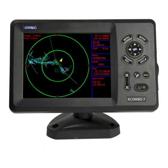
- Page 1 KCOMBO-7 OPERATOR'S MANUAL GPS CHART PLOTTER WITH FISHFINDER...
- Page 2 Continued use of the equipment can cause fire or electrical shock.Contact Connection of an incorrect power ONWA agent for service. supply can cause fire or equipment damage. Use the proper fuse. Use the proper fuse.
-
Page 3: Table Of Contents
CONTENTS FOREWORD MAIN PERFORMANCE AND SPECIFICATIONS CONFIGERATION 1 OPERATION OVERVIEW Keypad instruction 1.2 Turning ON and OFF Power 1.3 Adjusting Brilliance and DIM Display Modes PLOTTER DISPLAY OVERVIEW Choosing the Display Range Moving the Cursor 2.3 Panning the PLOTTER Display 2.4 Centering Own Ship's Position 2.5 Coordinates 2.6 Map... - Page 4 4 WAYPOINT/MOB 4.1 Entering Waypoints 4.2 Entering the MOB Mark 4.3 Displaying Waypoint Name 4.4 Operation on the Waypoint Editing 4.5 Erasing Waypoints 5 ROUTES 5.1 Creating Routes 5.2 Editing Routes 5.3 Erasing Routes DESTINATION 6.1 Setting Destination by Cursor 6.2 Setting Destination by Waypoint (WPT) 6.3 Setting Route as Destination 6.4 Setting Track Data as Destination...
- Page 5 8.4 Editing Drawing Marks 8.5 Editing Drawing Lines 8.6 Editing Drawing Place Name 8.7 Erasing Drawing Marks 8.8 Erasing Drawing Lines 8.9 Erasing Drawing Place Name 9 OTHER SETTING 9.1 Map Scale 9.2 Unit of Measurement 9.3 Bearing Reference 9.4 Magnetic Variation 9.5 Deviation 9.6 Time 9.7 TTG/ETA speed...
- Page 6 11 ECHO SOUNDER OVERVIEW 11.1 Sonar mode 11.2 Gain 11.3 Range 11.4 TVG 11.5 Pic. Advance 11.6 Split ratio 11.7 Sonar Menu 11.8 Alarm 11.9 System Menu 11.10 Data Field 12 INSTALLATION 13 INTERCONNECTION DIAGRAW 14 DISPLAY SIZE 15 SHORTCUTS 16 DATA IN/OUT DESCRIPTION 17 MENU TREE 18 ABBREVIATIONS...
-
Page 7: Foreword
FOREWORD The KCOMBO ONWA GPS PLOTTER aid are specially designed for the vessel traffic management, ONWA is a professional brand of the domestic and foreign navigation products. The products are designed to be all-sealed and waterproof, can be rapid position-fixing and resistant to poor environment. The software is powerful by using the advanced ARM9 processors can be capable to display faster, and the design for operation is professional and reasonable, can be easy to use. -
Page 8: Main Performance And Specifications
Position format Degree of minutes and UTM Basemap Built-in Onwa K-Chart External Map SD Cards slot for C-Map MAX and ONWA K-Chart User data storage Internal backup of user settings, or external SD-card Plot Interval 5s to 60min 0.01nm to 10nm Automatic way Plotting scales 0.001nm to 1000nm... - Page 9 Power Supply 10.5 to 35VDC, current drain<1.0A at 12V Physical Size: 243mm(H)X155mm(W)X82mm(D) 0.6kg Weight: Display: 7-inches ColorTFT day-view LCD 800 600 pixels Input & Output Port: one opto-isolated input Port one RS232 Output Port Waterproofing: Display unit: IPX5 Temperature range: Display unit: -15 to +55 Antenna unit: -25...
-
Page 10: Equipment List
- 600W Bronze NMM40-50/200 - 600W Plastic NBM40-50/200 - 600W Airmar Bronze Transducer w/Temp seosor B45 Dual Frequency Transom Mount Transducer - 600W Onwa Transducer w/Temp seosor KTD-520_TM - 600W Airmar transducer w/Temp seosor P58 3) Temperature seosor Onwa Thru-Hull temperature seosor KTS-10K_TH... - Page 11 HD Fishfinder Characteristics Echo Color 16 colors (including background color) according to echo intensity. The background color is selectable from blue, light blue, white and black. Meters 5/10/20/40/80/150/200/300/600/1000 Basic Range Feet 15/30/60/120/200/400/600/1000/2000/3000 Fathoms 3/5/10/20/40/80/100/150/300/600 Range Shift 80 meters, 200 feet, 100fathoms Zoom Range Times 2,3,4,6 5/10meters,10/20feet, 2/5fathoms...
-
Page 12: Configeration
CONFIGERATION KA-07 (Optional) 10M or 15M Transducer (Optional) Display Unit... -
Page 13: Operation Overview
1. OPERATION OVERVIEW 1.1 Keypad instruction Plotter function: Moving the cursor upward or to change the setting. Sounder function: Moving the VRM upward. Plotter function: Moving the cursor to the right. Sounder function: Long Press - Activates feeding rate selection for picture advancement Short Press - Setting the depth range (setting upper range limit). -
Page 14: Turning On And Off Power
1.2 Turning ON and OFF Power Turning on the power Press the key. The unit beeps and displays the " ONWA " logo. After a few seconds, it starts up with the last used display mode. Turning off the power... -
Page 15: Display Modes
1.4 Display Modes Your unit has eleven display modes: PLOTTER SCREEN, NAVIGATOR SCREEN WIND SCREEN, POSITION SCREEN, SATELLITE SCREEN , HIGHWAY SCREEN, AIS SCREEN , SOUNDER SCREEN and PLOTTER + SOUNDER SCREEN. Press the [MODE] key to choose a display mode. Each time the key is pressed, the display mode changes in the sequence shown below. -
Page 16: Plotter Display Overview
2. PLOTTER DISPLAY OVERVIEW 2.1 Choosing the Zoom Display Range You may press to Zoom In and to Zoom Out as desired on the PLOTTER display. 2.2 Moving the Cursor Press the cursor pad to move the cursor. The cursor moves in the direction of the pressed arrow. -
Page 17: Panning The Plotter Display
2.3 Panning the PLOTTER Display Using the cursor, pan left, right, up or down on your desired area. Place the cursor at the edge of the screen to start panning. The display shifts in the direction opposite to cursor pad operation. 2.4 Centering Own Ship's Position Press the [ESC]... -
Page 18: Map
2.6 Map MENU 1. Press [ ] key in PLOTTER screen. 2. Choose and then press [ ] key to select. 3. Choose the layer ON or OFF as desired and then press [ " " " " ] key to finish. (K-Chart) (C-MAP) Perspective View... -
Page 19: Heading Line
4. Choose the layer "ON" as desired and then press [ ] key to finish. 5. Choose the layer "OFF" as desired and then press [ ] key to finish. 2.8 Heading Line 1. Press [MENU] key in PLOTTER screen. 2. -
Page 20: Cursor
4. Heading Line option: "COG Time Line" selection The length of heading line will vary according to the SOG to show the estimated point of destination after the set period. Example, if you set the COG Time Line to 10 minutes then the length of the heading line will point to the position that your boat will reach after 10 minutes. -
Page 21: Ship Shape/Color
2.10 Ship shape/color 1. Press [MENU] key in PLOTTER screen. 2. Choose Ship shape/color and then press [ENT] key to select. Press [ ] key and then press [ENT] 2.11 Range Circle 1. Press [MENU] key in PLOTTER screen. 2. Choose Range Circle and then press [ENT]... -
Page 22: Drawing
2.12 Drawing 1. Press [MENU] key in PLOTTER screen. 2. Choose Drawing and then press [ENT] key to select. 3. Choose "Mark" "Line" or "Place name" as desired and then press [ ] key to finish. 4. User can change the size of User Marks. -
Page 23: Palette
5. User can change the size of Drawing Lines. 2.13 Palette 1. Press [ MENU ] key in PLOTTER screen. 2. Choose Palette and then press [ ] key to select. 3. Choose "Normal ", "Daylight , "Night" " "NOAA" as desired and then press ] key to finish. -
Page 24: Map Direction
2.14 Map Direction 1. Press [MENU] key in PLOTTER screen. 2. Choose Map Direction and then press [ENT] key to select. 3. Choose Normal , " " " North Up , " " WPT Up or " "COURSE Up as desired and then "... -
Page 25: Track
3. TRACK 3.1 Changing Track Plotting Interval, Stop Plotting When the track memory becomes full, the oldest track is erased to make room for the latest. 1. Press the [MENU] key twice to enter main menu. 2. Choose Track record and then press key to select. -
Page 26: Displaying The Track
3.2 Displaying the Track 1. Press [MENU] key in PLOTTER screen. 2. Choose Track and then press key to select. 3. Choose the color and if you want to turn it ON or OFF . " " " " 4. Press [ MENU ] key to finish. -
Page 27: Erasing Track
3.4 Erasing Track 1. Press [MENU] key twice to enter main menu. 2. Choose Erase and then press key to select. 3. Choose Current track Saved track 4. If Saved track is chosen, press key to choose the color that you want to erase or choose if you want to erase all tracks and then press [ENT]... -
Page 28: Waypoint/Mob
4. WAYPOINT/MOB 4.1 Entering Waypoints Waypoints can be entered on the PLOTTER display in three ways: by cursor position, at own ship's position, and from the waypoint edit. Entering a waypoint with the cursor 1. Use the cursor pad to place the cursor on the location desired for a waypoint. [ENT] 2. - Page 29 Entering a waypoint from the waypoint list 1. Press the [MENU] key twice to enter main menu. 2. Choose Edit and then press key to select. 3. Choose Waypoint and then press [ ] key. The following window will appear 4.
-
Page 30: Entering The Mob Mark
4.2 Entering the MOB Mark Only one MOB mark may be entered. Each time the MOB mark is entered, the previous MOB mark and its position data are over-written. [MOB] 1. Long press the key on any display mode. The following display appears. 2. -
Page 31: Operation On The Waypoint Editing
4. User can change the size of Waypoint Marks 4.4 Operation on the Waypoint Editing Waypoint position, waypoint name, mark shape, mark color and comment can be edited from the Waypoint Edit. 1. Press the [ MENU ] key twice to enter main menu. 2. -
Page 32: Erasing Waypoints
4.5 Erasing Waypoints 1. Press the [MENU] key twice to main menu. 2. Choose Edit and then press key to select. 3. Choose Waypoint and then press the [ENT] key. The following window will appear. 4. Select a waypoint and press [ENT] key. -
Page 33: Routes
5. ROUTES 5.1 Creating Routes 1. Press [MENU] key twice to enter main menu. 2. Choose Edit and then press key to select. 3. Choose Route and then press [ENT] key. The following window will appear. 4. Choose NEW and then press [ "... - Page 34 5. Use [ ] or [ ] to enter the route name and then press [ ] key to finish. The following will appear. 6. Choose the location (e.g. 01) and then press [ ] key. A new window will open which will let you choose a waypoint. 7.
-
Page 35: Editing Routes
5.2 Editing Routes Replacing waypoints in a route 1. Press the [MENU] key twice to enter main menu. 2. Choose Edit and then press key to select. 3. Choose Route and then press [ENT] key to select. 4. Choose the route to edit and then press [ENT] key. -
Page 36: Erasing Routes
Permanently deleting a waypoint from a route 1. Press the [MENU] key twice to enter main menu. 2. Choose Edit and then press the key to select. 3. Choose Route and then press [ENT] key to select. 4. Choose the route desired and then press [ENT] key to select. - Page 37 4. Select a route then press [ENT] key. 5. The confirm window will appear. Choose "ERASE " and then press [ENT] key. 6. Choose " " and then press [ ] key to finish. Erase All Routes 1. Press the [MENU] key twice to enter main menu.
-
Page 38: Destination
6. DESTINATION 6.1 Setting Destination by Cursor 1. Press key to display the FUNCTION window. 2. Choose Goto cursor and then press [ENT] key to select. 3. The cursor appears with ? . " " 4. Use the cursor pad to place the cursor on the location desired for destination. 5. -
Page 39: Setting Destination By Waypoint (Wpt)
6.2 Setting Destination by Waypoint (WPT) FUNCTION 1. Press the key to display the window. 2. Choose Goto WPT and then press [ ] key to select. 3. The WAYPOINT list appears. 4. Choose a waypoint and then press [ ] key to finish. - Page 40 3. The ROUTE list appears. 4. Choose a route and then press [ ] key. The following window appears. 5. Choose Forward or Reverse in order to traverse the waypoints in the route, and " " " " then press [ ] key to finish.
-
Page 41: Setting Track Data As Destination
6.4 Setting Track Data as Destination Track Data can be used for navigation. 1. Press the key to display the FUNCTION window. Goto track [ENT] 2. Choose and then press the key to select. 3. The SAVED TRACK window will appear. 4. -
Page 42: Canceling Destination
Once a Goto track has been activated, the track will divide it into segments. Up to 200 temporary waypoints are created (named T1,T2, T3, etc. and END) to mark the most significant features of the track, duplicating your exact path as closely as possible. -
Page 43: Distance
6.6 Distance Measure the distance of several points and save it as a route. 1. Press key in PLOTTER screen to display FUNCTION window. Distance [ENT] 2. Select " " and press key to activate the distance measurement function. Note: a) LON/LAT is the position of the cursor (point C) b) BRG is the bearing of cursor to the last point (point B) Fig.3... - Page 44 6. Move the cursor to the next point (C). Now the BRG and LEG displays the Bearing and Distance from point B to point C. DIST displays the total distance from point A to point B. 7. Press [ ] key, now DIST = distance of point AB + distance of point BC is shown, while BRG and LEG turns to 0.
-
Page 45: Alarm
7. ALARM There are six alarm conditions which generates both audio and visual alarms: Arrival alarm Anchor drag alarm XTE (Cross-Track Error) alarm Speed alarm Voltage alarm Timer alarm When the alarm setting is violated, the buzzer sounds and the name of the offending alarm and the alarm icon appears on the display. -
Page 46: Arrival Alarm
3. Choose Anchor and then press [ ] key. The alarm options appear. 4. Press [ ] key to select the alarm value and then press [ ] key to setup the value. 5. Choose ON and then press [ "... -
Page 47: Xte (Cross-Track Error) Alarm
7.3 XTE (Cross-Track Error) Alarm XTE (Cross-Track Error) Alarm warns you when own ship is off its intended course. [MENU] 1. Press key twice to enter main menu. Alarm ALARM 2. Choose and then press key to display menu. 3. Choose and then press [ENT] key. -
Page 48: Voltage Alarm
7.5 Voltage Alarm Voltage Alarm warns you when the input voltage in the unit is higher than the set value. MENU 1. Press [ ] key to enter main menu. 2. Choose Alarm and then press [ ] key to display ALARM menu. 3. -
Page 49: Buzzer Type Selection
7.7 Buzzer Type Selection The buzzer sounds whenever an alarm setting is violated. 1. Press the [MENU] key twice to enter main menu. 2. Choose Alarm and then press key to select. 3. Choose Buzzer and then press key to select. 4. -
Page 50: Drawing
8. DRAWING 8.1 Drawing Marks 1. Press [ ] key to display the FUNCTION window. 2. Choose Drawing and then press [ ] key to select. 3. Choose Mark and then press [ ] key. The cursor appears with "+?" on the PLOTTER screen. 4. -
Page 51: Drawing Lines
8.2 Drawing Lines 1. Press [ ] key to display the FUNCTION window. 2. Choose Drawing and then press [ ] key to select. 3. Choose Line and then press [ ] key. The cursor appears with "+?" on the PLOTTER screen. -
Page 52: Editing Drawing Marks
8.4 Editing Drawing Marks 1. Press [MENU] key twice to enter main menu. 2. Choose Edit and then press key to select. Drawing marks [ENT] 3. Choose and then press key. The following window appears. 4. Select a mark then press [ ] key to edit. -
Page 53: Editing Drawing Lines
8.5 Editing Drawing Lines 1. Press [ MENU ] key twice to enter main menu. 2. Choose Edit and then press [ ] key to select. 3. Choose Drawing lines and then press [ ] key. The following window appears. 4. -
Page 54: Editing Drawing Place Name
8.6 Editing Drawing Place Name 1. Press [ MENU ] key twice to enter main menu. 2. Choose Edit and then press [ ] key to select. 3. Choose Drawing placename and then press [ ] key. The following window appears. 4. -
Page 55: Erasing Drawing Marks
8.7 Erasing Drawing Marks 1. Press [MENU] key twice to enter main menu. 2. Choose Edit and then press key to select. Drawing marks [ENT] 3. Choose and the press Key. 4. Choose the mark that you want to clear, and then press [ENT] key. -
Page 56: Erasing Drawing Lines
8.8 Erasing Drawing Lines 1. Press [MENU] key twice to enter main menu. 2. Choose Edit and then press key to select. Drawing lines [ENT] 3. Choose and the press key to select. 4. Choose the line that you want to erase, and then press [ENT] key. -
Page 57: Erasing Drawing Place Name
8.9 Erasing Drawing Place Name 1. Press [MENU] key twice to enter main menu. 2. Choose Edit and then press key to select. 3. Choose Drawing placename and then press [ENT] key to select. 4. Choose the place name that you want to erase, and then press [ENT] key. -
Page 58: Other Setting
9. OTHER SETTING 9.1 Map Scale You can change the map scale display format. 1. Press [MENU] key twice to enter main menu. 2. Choose Setup and then press key to select. 3. Choose Map scale and then press [ ] key to select. -
Page 59: Bearing Reference
Depth Unit 1. Press [MENU] key twice to enter main menu. 2. Choose Setup and then press key to select. 3. Choose Depth unit and then press [ENT] key to select. 4. Choose "f eet , " "f athom or "... -
Page 60: Magnetic Variation
9.4 Magnetic Variation The location of the magnetic North Pole is different from the geographical North Pole. This causes a difference between the true and magnetic north direction. This difference is called magnetic variation, and varies with respect to the observation point on earth. -
Page 61: Deviation
9.5 Deviation You can input the deviation of the ship or map manually to correct the position error from GPS error or map error. 1. Press [ MENU ] key twice to enter main menu. 2. Choose Setup and then press [ ] key to select. -
Page 62: Ttg/Eta Speed
9.7 TTG/ETA speed To calculate time-to-go and estimated time of arrival, enter your speed as below. 1. Press the [MENU] key twice to enter main menu. 2. Choose Setup and then press key to select. 3. Choose TTG/ETA speed and then press [ENT] key select. -
Page 63: Gps Setting
4. Choose and then press [ ] key to finish. The following message appears 9.10 GPS setting 9.10.1 Choosing GPS output data The unit s default is using an internal GPS module for position fixing. On the other hand, you can use external GPS data for position fixing. 1. - Page 64 9.10.2 Datum setting You can choose 6 types of data output at the same time. 1. Press [MENU] on the SATELLITE screen. 2. Choose Datum and press [ENT] key to select. 3. Choose your desired datum and press [ ] key to confirm. 9.10.3 Smoothing You can setup position smoothing, speed smoothing and course smoothing.
-
Page 65: Nmea Data Display
9.11 NMEA data display 1. Press [ MENU ] key twice to enter main menu. 2. Choose Setup and then press [ ] key to select. NMEA 3. Choose data display and then press [ ] key. 4. NMEA data display is used during the installation to check whether the NMEA input and output data to and from other equipment onboard is normal. -
Page 66: The Ais Funtion
10. THE AIS FUNCTION 10.1 Vessels list 1. Press [MENU] on the screen. 2. Choose AIS detail list and then press [ ] key. The AIS SHIP LIST window will appear. 10.2 The collision alarm 1. Press [ MENU ] on the AIS screen. 2. -
Page 67: Own Ship's Information
10.3 Own ship's information There are two ways to display Own Ship Info " " 1. Enter the "Vessels list" , and press the [MENU] key, and then select the " Ship Info " to check all the information of your own ship. 2. -
Page 68: View Ais Vessels' Information On Chart Screen
10.5 View AIS vessels' information on chart screen There are two ways to view AIS vessels' information: one is to move the cursor to select AIS vessel on the charts screen, and press the [ ] key. The other is to select the AIS vessel from the AIS vessels list, and press the ] key. -
Page 69: Emergency Alarm
10.7 Emergency alarm The information of the emergency alarm received is displayed on the bottom right corner. The emergency alarm is always available and can not be deleted, if the emergency alarm information is not read, after exiting the alarm menu, the "emergency alarm"... -
Page 70: Ais Vessel
10.9 AIS Vessel 1. User can define the AIS vessel display as either " Fill " " Line " Fill Line... -
Page 71: Echo Sounder Overview
11. HD FISHFINDER OVERVIEW 11.1 Sonar mode [MENU] SOUNDER 1. Press key in screen. 2. Choose Sonar mode and then press [ENT] key or press and hold [MODE] key in the SOUNDER screen. The following window will appear. Function MODE Provides the high frequency (200KHz)normal picture on the full screen. - Page 72 200KHz, 50KHz (high frequency, low frequency) mode The sounder uses ultrasonic pulses to detect bottom conditions. The lower the frequency of the pulse the wider the detection area. Therefore, the 50KHz frequency is useful for general detection and judging bottom conditions, while the 200KHz frequency is useful for detailed observation of fish schools.
-
Page 73: Gain
11.2 Gain 1. Press [MENU] key in SOUNDER screen. 2. Choose Gain and then press [ENT] key, or press [ENT] key in the SOUNDER screen to adjust gain manually. The following window will appear. 3. Choose Manual, Fishing or Cruising as desired and then press the [ENT] key, or press and hold [ENT]... -
Page 74: Tvg
11.4 TVG 1. Press [MENU] key in SOUNDER screen. 2. Choose and then press [ENT] key. The following window will appear. " " " Manual " [ENT] 3. Choose as desired then press key. The TVG compensates for propagation loss of sound, so that the echoes from the same fish school size are displayed in the same color. -
Page 75: Pic. Advance
11.5 Picture advance The picture advance speed determines how quickly the vertical scan lines run across the screen. 1. Press [MENU] key in SOUNDER screen. 2. Choose Pic. advance and then press [ENT] key or press and hold key in SOUNDER screen. -
Page 76: Sonar Menu
11.7 Sonar Menu 1. Press [MENU] key in SOUNDER screen. 2. Choose Sonar menu and then press [ENT] key. The following window will appear. 11.7.1 A-Scope 1. Press [MENU] key in SOUNDER screen. 2. Choose Sonar menu and then press [ENT] key to select. - Page 77 11.7.2 Zoom modes 1. Press [MENU] key in SOUNDER screen. 2. Choose Sonar menu and then press [ENT] key to select. 3. Choose Zoom mode and then press [ENT] key. The following window will appear. 4. Choose "Marker Zoom" "Bottom lock" "Bottom zoom"...
- Page 78 BOTTOM LOCK This display provides a compressed normal picture on the top 2/3 of the screen and a 5 or 10 meter (10 or 20 feet) wide layer in contact with the bottom is expanded onto the bottom 1/3 of the screen. This mode is useful for bottom discrimination. Note that the seabed should be steadily and distinctly plotted in red or reddish-brown.
- Page 79 11.7.3 Noise limiter Light-blue dots may appear over most of the screen. This is mainly due to unclean water or noise. This noise can be suppressed by adjusting Clutter on the menu. 1. Press [MENU] key in SOUNDER screen. 2. Choose Sonar menu and then press [ENT]...
- Page 80 11.7.5 Signal level 1. Press [MENU] key in SOUNDER screen. 2. Choose Sonar menu and then press [ENT] key to select. 3. Choose Signal level and then press [ENT] key. The following window will appear. 4. Press the [ ] or [ ] key to select the signal level and press [ ] key to finish.
-
Page 81: Alarm
11.8 Alarm 1. Press [MENU] key in SOUNDER screen. 2. Choose ALARM and then press [ENT] key. The following window will appear. 3. Press [] or [] key to select an alarm. 4. Press [ ] key to select "OFF", "ON", "IN"... -
Page 82: System Menu
11.9 System Menu [MENU] SOUNDER 1. Press key in screen. 2. Choose System menu and then press [ENT] key. The following window will appear. RANGE 1- 10: Activates or deactivates specific range scales. Default ranges are 5, 10, 20, 40, 80, 150, 200, 300, 600, and 1000 (meters). Setting area is 2m to 800m. Note: Ranges must be set in numerical order. -
Page 83: Data Field
11.10 Data field 1. Press [MENU] key in SOUNDER screen. 2. Choose Data field and then press [ENT] key. The following window will appear. 3. Data field setup The Data Field will appear on the right-side of the screen. The black area is the data area of which may be changed. -
Page 84: Installation
12. INSTALLATION Control/Display Unit Mounting Bracket Notice: The unit should be mounted on a flat, solid surface for maximum stability. Be sure to fix the mounting bracket with screws. Otherwise, the display unit may fall down by the boat s pitching and rolling to the lead to the fire or the injury. (1) The mounting bracket should be fixed with 6mm screws. -
Page 85: Interconnection Diagraw
13. INTERCONNECTION DIAGRAM DATA INPUT/OUTPUT NMEA0183 IN+ (Orange) GPS ANTENNA NMEA0183 IN (Yellow) Power +(Red) ONWA Ignition_On (Brown) NMEA0183 OUT+ <RS-232> (White) Engineer Port (Blue) Built-in GPS antenna DC5V OUT (Green) Power (Black)/Shield TRANSDUCER SONAR+ SPEED/TEMP.GND SPEED+ TEMP. SONAR- SONAR GND... -
Page 86: Display Size
14. DISPLAY SIZE... -
Page 87: Shortcuts
15. SHORTCUTS Shortcuts in Plotter screen 1) Press and hold [ MODE ] to change the track color. 2) Press and hold [ ] to turn track record on and off. 3) Press and hold [ ] to activate the User Mark drawing function. Shortcuts in Fishfinder (Sounder) screen 1) Press and hold [ MODE... -
Page 88: Data In/Out Description
16. DATA IN/OUT DESCRIPTION NMEA0183 IN+ NMEA Input & AIS input from external equipment NMEA0183 IN Power + Ignition_On (Brown) Ignition Ignition Switch POWER-/GND 10.5~35VDC NMEA0183 OUT+(RS-232) NMEA 0183 output to external equipment Engineer Port DC5V OUT DC 5V OUT 150 mA... -
Page 89: Menu Tree
17. MENU TREE MAIN TRACK TIME: 5S/ TRACK RECORD MODE ( TIME/DISTANCE/AUTO/OFF) MENU RECORD 10S 30S/1min/ 5min/10min/ SAVED TRACK(... 30min/60min SAVE CURRENT TRACK(SAVE/EXIT) DISTANCE: SET UP MAP SCALE (MILES/RATIO) SPEED UNIT(NM,KT /KM,KMH/SM,KPH) DEPTH UNIT(FEET /FATHOM/METER) BRG REF.( TRUE/MAGNETIC) MAG REF. ( AUTO /MANUAL) DEVIATION( LAT: +00.000, LON: + 00.000) TIME(24H/+00) TTG/ETA SPEED(AUTO/MANUAL) - Page 90 MAIN ALARM ANCHOR MODE: (ON/OFF) MENU CONTINUE DISTANCE: 0.50 ARRIVAL MODE: (ON/OFF) DISTANCE: 0.50 MODE: (ON/OFF) DISTANCE: 0.50 SPEED MODE: (HI/LO/OFF) SPEED: 20.0 MODE: (ON/OFF ) VOLTAGE VOLT: 8.50 TIMER MODE: (ON/OFF ) TIME : 050 BUZZER MODE: (SHORT/LONG/CONST) WARNING MESSAGE EDIT WAYPOINT(WAYPOINT EDIT MENU ) ROUTE(ROUTE EDIT MENU )
- Page 91 FUNCTION GOTO CURSOR( G OTO CURSOR FUNCTION ) GOTO WPT(GOTO WPT FUNCTION ) GOTO ROUTE(GOTO ROUTE FUNCTION ) GOTO TRACK(GOTO TRACK FUNCTION ) STOP GOTO(TURN OFF GOTO) DRAWING(MARK,NAME,LINE ) TIDE TABLE (TIDE TABLE FUNTION) SEARCH(SEARCH FUNCTION ) CALENDAR PLOTTER NAVIGATOR WIND POSITION HIGHWAY...
- Page 92 MENU TRACK COLOR 1 (ON/OFF) COORDIMATE (N/E/UTM) PLOTTER COLOR 2 (ON/OFF) PLACE NAME ( ON/OFF) COLOR 3 (ON/OFF) NAME TAGS ( ON/OFF) COLOR 4 (ON/OFF) NAV AIDS/LIGHTS (ON/OFF) COLOR 5 (ON/OFF) ATTENTION AREA (ON /OFF) COLOR 6 (ON/OFF) TIDES/CURRENTS ( O N/OFF) COLOR 7 (ON/OFF) SEABED TYPE (ON/OFF) COLOR 8 (ON/OFF)
- Page 93 POSITION MENU -POS DATA FIELD HDOP BEARING RANGE TIME VOLTAGE DESTI N ATION DATE LUNAR DATE NORTH UP / WPT UP/BOW UP MENU-NAV POSITION HDOP SETUP DATA FIELD BEARING RANGE TIME VOLTAGE DESTINATION DATE LUNAR DATE...
- Page 94 MENU -AIS ACTIVATION RING (05.00NM) CPA LIMIT (05.00NM ) TCPA LIMIT (10MIN) CPA/ TCPA ALARM (ON/OFF ) STATUS AIS SHIP LIST MENU -SAT INPUT(INTER NAL/EXTERNAL) OUTPUT( OFF/NO GGA,GLL,RMC BUAD RATE(4800/9600/19200/38400) DATUM(WGS84 /LISTING) GPS SBAS(OFF/ON) POS SMOOTH ( 0 10) SOG SMOOTH( 0 60) COG SMOOTH( 0 05) DATA FIELD SETUP...
-
Page 95: Abbreviations
18. ABBREVIATIONS Abbreviations Word Escape Enter Satellite-based augmentation system SBAS Position Speed Over Ground Course Over Ground Apparent Wind Speed Apparent Wind Angle True Wind Speed True Wind Angle True Wind Direction Velocity Made Good Information INFO Latitude Longtitude Total Time to Go Estimate Time of Arrival Cross Track Error Horizontal Dilution of Precision... -
Page 96: Glossary
19. GLOSSARY (AIS) Regional Assignment Channel Assignment Message Acknowledgement (AIS) Channel management information source messages AFSK Auto frequency-shift keying (AIS) Alarm Message A to N Aid to Navigation Automatic Identification System BIIT Built In Integrity Testing Bayonet fitting type Therefore connector Course over Ground Carriage Return Carrier Sense... - Page 97 MMSI Maritime Mobile Service ldentity Maximum Permissible Exposure NMEA National Marine Electronics Association Personal Computer Presentation Interface Radio Frequency RTCM Radio Technical Commission for Maritime Services Commission Receive or Receiver Radio Frequency Interference Specific Absorption Rate SELV Separated Extra Low Voltage Short Message System Speed over Ground Safety Related Message...
Need help?
Do you have a question about the KCOMBO-7 and is the answer not in the manual?
Questions and answers