
Subscribe to Our Youtube Channel
Related Manuals for Ventrac KA160

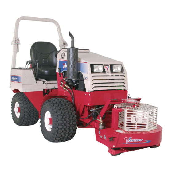
Summary of Contents for Ventrac KA160
- Page 1 Operator’s Manual & Parts Drawings Power Blower Model KA160 Revised 01/18/17 Original Operator’s Manual 09.10016 Rev. 05...
- Page 2 To the Owner Contact Information and Product Identification If you need to contact an authorized Ventrac dealer for information on servicing your product, always provide the product model and serial numbers. Please fill in the following information for future reference. See the picture(s) below to find the location of the identification numbers.
-
Page 3: Table Of Contents
Operating On Slopes ..........................9 Roadway Safety .............................9 Truck Or Trailer Transport ........................9 Maintenance ............................10 Fuel Safety ............................10 Hydraulic Safety ........................... 11 KA160 Safety Procedures ........................12 OPERATIONAL CONTROLS PAGE 13 Hydraulic Rotational Control ........................13 Blower Deflector ...........................13 Weight Transfer ............................13 GENERAL OPERATION PAGE 14 Daily Inspection ............................14... -
Page 4: Introduction
Ventrac dealer for a replacement. When using a Ventrac attachment, be sure to read and follow the safety and operating instructions of both the power unit and the attachment being used to ensure the safest operation possible. -
Page 5: Using Your Manual
Manual Glossary Power Unit A Ventrac tractor or other Ventrac engine powered device that may be operated by itself or with an attachment or accessory. Attachment A piece of Ventrac equipment that requires a Power Unit for operation. -
Page 6: Safety
SAFETY Safety Decals The following safety decals must be maintained on your KA160 power blower. Keep all safety decals legible. Remove all grease, dirt, and debris from safety decals and instructional labels. If any decals are faded, illegible, or missing, contact your dealer promptly for replacements. -
Page 7: General Safety Procedures
SAFETY General Safety Procedures for Ventrac Power Units, Attachments, & Accessories Training Required • The owner of this machine is solely responsible for properly training the operators. • The owner/operator is solely responsible for the operation of this machine and prevention of accidents or injuries occurring to him/her- self, other people, or property. -
Page 8: Preventing Accidents
SAFETY General Safety Procedures for Ventrac Power Units, Attachments, & Accessories Operation Safety (continued) • If equipped with a high/low range feature, never shift between high and low range while on a slope. Always move the machine to level ground and engage the parking brake before shifting range. -
Page 9: Operating On Slopes
SAFETY General Safety Procedures for Ventrac Power Units, Attachments, & Accessories Operating On Slopes • Slopes can cause loss-of-control and tip-over accidents, which can result in severe injury or death. Be familiar with the emergency parking brake, along with the power unit controls and their functions. -
Page 10: Maintenance
• If the power unit, attachment, or accessory requires repairs or adjustments not instructed in the operator’s manual, the power unit, attachment, or accessory must be taken to an authorized Ventrac dealer for service. • Never perform maintenance on the power unit and/or attachment if someone is sitting in the operator’s seat. -
Page 11: Hydraulic Safety
SAFETY General Safety Procedures for Ventrac Power Units, Attachments, & Accessories Fuel Safety (continued) • Do not overfill fuel tank. Only fill to bottom of fuel neck, do not fill fuel neck full. Overfilling of fuel tank could result in engine flooding, fuel leakage from the tank, and/or damage to the emissions control system. -
Page 12: Ka160 Safety Procedures
SAFETY KA160 Safety Procedures • Remove any loose objects from the work area. The power blower produces strong wind speeds and could blow loose objects at high velocity, causing damage or injury to other objects, buildings, vehicles, people, or animals. -
Page 13: Operational Controls
OPERATIONAL CONTROLS Hydraulic Rotational Control The KA160 power blower (Serial # 1097 -) is equipped with hydraulic rotational control of the blower discharge. The discharge direction is con- trolled using the secondary SDLA control lever* of the power unit. The KA160 power blower (Serial # 1001-1096) is equipped with a manual rotation lock lever. -
Page 14: General Operation
GENERAL OPERATION Daily Inspection pulley of the power unit. 6. Disconnect the hydraulic quick couplers from the power unit and store the hose ends in the top frame holes on the power blower. 7. Disengage the front hitch locking lever*. Always set the parking brake, shut off power unit engine, remove the ignition key, and ensure 8. -
Page 15: Service
Attention If any component requires replacement, use only original Ventrac replacement parts. Cleaning and General Maintenance Remove the plug (A) from the gearbox to check the For best results, and to maintain the finish of the oil level. -
Page 16: Gearbox Drive Belt Replacement
SERVICE Gearbox Drive Belt Replacement 4. Remove the old rotation belt. 5. Install the new rotation belt and engage the rota- 1. Detach the power blower from the power unit. tion belt tensioning spring. 2. Remove the belt shield from the gearbox. 6. -
Page 17: Specifications
SPECIFICATIONS Dimensions Overall Height ........20 inches (51 cm) Overall Length . -
Page 18: Parts
PARTS ILLUSTRATED DRAWING Main Frame Use only original Ventrac Illustrated Parts - 18 replacement parts. - Page 19 10 ..40.0278 ....SHAFT, PIVOT, BELT IDLER KA160 ..
-
Page 20: Fan Housing
PARTS ILLUSTRATED DRAWING Fan Housing Use only original Ventrac Illustrated Parts - 20 replacement parts. - Page 21 36 ..85.K0408 ....KEY, 1/4 X 1 ............. . 1 *as required. Use only original Ventrac Illustrated Parts - 21...
-
Page 22: Hydraulic Rotational Control
PARTS ILLUSTRATED DRAWING Hydraulic Rotational Control Hydraulic rotational control is a standard feature beginning with serial # AA1097. Use only original Ventrac Illustrated Parts - 22 replacement parts. - Page 23 13 ..05.0116 ....WASHER, .544ID X .817 X.14 RED ......... . . 1 Use only original Ventrac Illustrated Parts - 23 replacement parts.
-
Page 24: Warranty
V.P.I. V.P.I.’s responsibility in respect to claims is limited to making the required repairs or replacements, and no claim of breach of warranty shall be cause for cancellation or rescission of the contract of sale of any Ventrac equipment. - Page 25 (ii) loss, cost, or expense relating to transportation or delivery of turf equipment from the location of owner or location where used by owner to or from any authorized Ventrac dealer; (iii) travel time, overtime, after hours time or other extraordinary repair charges or charge relating to repairs or replace- ments outside of normal business hours at the place of business of an authorized Ventrac dealer;...
Need help?
Do you have a question about the KA160 and is the answer not in the manual?
Questions and answers