
Related Manuals for Iso-Tech IPS1820D

Summary of Contents for Iso-Tech IPS1820D
-
Page 1: Dc Power Supply
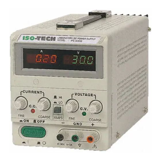
DC POWER SUPPLY (Switching mode) ISO-TECH IPS1820D RS Stock No. 357-0760 ISO-TECH IPS3610D RS Stock No. 357-0776 ISO-TECH IPS606D RS Stock No. 357-0782 82IP-3610DMB... -
Page 2: Safety Terms And Symbols
SAFETY TERMS AND SYMBOLS These terms may appear in this manual or on the product: WARNING. Warning statements identify condition or practices that could result in injury or loss of life. CAUTION. Caution statements identify conditions or practice that could result in damage to this product or other property. - Page 3 FOR UNITED KINGDOM ONLY As the colours of the wires in main leads may not correspond with the colours marking NOTE identified in your plug/appliance, proceed as follows: This lead/appliance must only be wired by competent persons The wire which is coloured Green & Yellow must be connected to the Earth terminal marked WARNING with the letter E or by the earth symbol or coloured Green or Green &...
- Page 4 Statement of Compliance IPS-1820D, IPS-3610D, IPS-606D are herewith confirmed to comply with the requirements set out in the Council Directive on the Approximation of the Law of Member States relating to Electromagnetic Compatibility (89/336/EEC,92/31/EEC,93/68/EEC) and Low Voltage Equipment Directive(73/23/EEC). For the evaluation regarding the Electromagnetic Compatibility and Low Voltage Equipment Directive, the following standards were applied: EN 61326-1: Electrical equipment for measurement, control and laboratory use—EMC requirements (1997+A1:1998 )
-
Page 5: Table Of Contents
CONTENTS SECTION PAGE INTRODUCTION…………………………………………………………………………….……………………… SPECIFICATIONS…………………………………………………………………………………………………… 2-1 General…………………………………………………………………………………….……………………. 2-2 Constant Voltage Operation…………………………………………………………………………………… 2-3 Constant Current Operation…………………………………………………………………………………... 2-4 Indicator Meter…………………………………………………………………………………………………. 2-5 Insulation………………………………………………………………………………………………………... PRECAUTIONS BEFORE OPERATION………………………………………………………………………….. 3-1 Unpacking the Switching Power Supply……………………………………………………………………… 3-2 Checking the line voltage………………………………………………………………………………………. 3-3 Environment……………………………………………………………………………………………………. 3-4 Equipment installation and operation………………………………………………………………………… THEORY OF OPERATION…………………………………………………………………………………………... -
Page 6: Introduction
1. INTRODUCTION This series of switched mode power supplies have removed the inconvenience of big volumes and heavyweight associated with traditional power supplies. The output voltage and current are controlled by two variable resistors with coarse and fine regulation for simple and precise adjustment. -
Page 7: Specifications
2.SPECIFICATION 2-1. General Mains supply : 115V/230V±15% 50/60Hz(Switch selectable). Rating, dimension and weight : See Table 2-1. Table 2-1 MAX. RATING INPUT RATING FUSE STYLE & RATING WEIGHT Model Voltage Current Watts 115V 230V IPS-1820D T 10A 250V T 6.3A 250V IPS-3610D T 10A 250V T 6.3A 250V... -
Page 8: Constant Voltage Operation
2-2.Constant Voltage Operation (1) Output Voltage ranges from 0 to rated voltage with continuous adjustment. (2) Voltage regulation line regulation≦5mV. load regulation≦5mV. (3) Recovery time≦500µs(50% Load change, minimum load 0.5A). (4) Ripple & Noise≦5mVrms, 100mVp-p (tested by 20MHz oscilloscope.) (5) Temperature coefficient≦100ppm/℃. 2-3.Constant Current Operation (1) Output current ranges from 0 to rated current with continuous adjustment. -
Page 9: Precautions Before Operation
3. PRECAUTIONS BEFORE OPERATION 3.1 Unpacking the Switched ModePower Supply The instrument has been fully inspected and tested before shipping from the factory. Upon receiving the instrument, please unpack and inspect it to check if there is any damages caused during transportation. If any sign of damage is found, notify the bearer and/or the dealer immediately. -
Page 10: Environment
3.3 Environment The normal ambient temperature range of this instrument is from 0° to 40°C (32° to 104°F). Operation of the instrument above this temperature range may cause damage to the circuits. Do not use the instrument in a place where strong magnetic or electric fields exist as they may disturb the measurement. -
Page 11: Theory Of Operation
4.THEORY OF OPERATION Block Configuration of IPS- System The IPS-Series comprise a Bridge rectifier, a Pulse Width Modulation, a Driver Circuit, a Driver Transformer, a Rectifier Circuit, a Voltage Control Circuit, a Current Shunt, an Output Filter, a Voltage/Current Adjusting Circuit, a Buffer Circuit, an Error Amplifier, an Opto-Isolator, and an Auxiliary Switching Supply and etc. - Page 12 Description of Circuit Theory 1) +10V Voltage reference circuit: Start up the circuits of R306 and D302 to ensure the output voltage of OPA U301, PIN 1 is in positive status when power is on. At this moment, the output voltage of PIN 1 will pass through R307 to maintain the voltage of both ends of ZENER DIODE ZD301(6.2V) to 6.2V.
- Page 13 Figure 1: Block Diagram...
-
Page 14: Panel Controls And Indicators
5.PANEL CONTROLS AND INDICATORS 5-1.Front panel(Fig. 4-1) CV Indicator Lights when the power is on and in constant voltage operation. CC Indicator Lights when in constant current operation. Voltage coarse For the coarse adjustment of the output voltage. Voltage fine For the fine adjustment of the output voltage. - Page 15 Fig. 4-1 Front Panel...
- Page 16 Fig. 4-2 Rear Panel...
-
Page 17: Operation Instructions
6.OPERATION INSTRUCTIONS 6-1.Precaution (1)AC input AC input should be within the range of line voltage±15% 50/60Hz. WARNING: To avoid electrical shock, the power cord protective grounding conductor must be connected to ground. (2)Installation Avoid using the power supply in a place where ambient temperature exceeds 40℃. The heat sink located at rear of the power supply must have sufficient space for radiation. -
Page 18: Constant Voltage/Constant Current Characteristic
6-3.Constant Voltage / Constant Current Crossover Characteristic The working characteristic of this series is called a constant voltage/constant current automatic crossover type. This permits continuous transition from constant current to constant voltage modes in response to the load change. The intersection of constant voltage and constant current modes is called the crossover point. -
Page 19: Operation Mode
Similarly, crossover from the constant current to the constant voltage mode automatically occurs from a decrease in load, a good example of this would be seen when charging a 12 volt battery. Initially, the open circuit voltage of the power supply may be preset for 13.8 volts. A low battery will place a heavy load on the supply and it will operate in the constant current mode, which may be adjusted for a 1 amp charging rate. -
Page 20: Maintenance
7. MAINTENANCE WARNING The following instructions are used by qualified personnel only. To avoid electrical shock, do not perform any servicing other than the operating instructions of the manual unless you are qualified to do so. 7-1.Fuse Replacement If the fuse blown, the CV or CC indicators will not light and the power supply will not operate. The fuse should not normally blow unless a problem has developed in the unit. -
Page 21: Adjustment
7-3.Internal adjustments The unit was accurately adjusted at the factory before shipment. So, readjustment is suggested only when the accuracy of circuit is affected by the repair, or when you have the reason to believe that the unit is out of accuracy. The recommended calibration device is a multimeter with an accuracy of ±0.1% dcv or better. -
Page 23: Cleaning
7-4 Cleaning To clean the power supply, use a soft cloth dampened in a solution of mild detergent and water. Do not spray cleaner directly onto the instrument, since it may leak into the cabinet and cause damage. Do not use chemicals containing benzine, benzene, toluene, xylene, acetone, or similar solvents.
Need help?
Do you have a question about the IPS1820D and is the answer not in the manual?
Questions and answers