Table of Contents
Advertisement
Advertisement
Table of Contents

Related Manuals for Iso-Tech IPS 3303D

Summary of Contents for Iso-Tech IPS 3303D
-
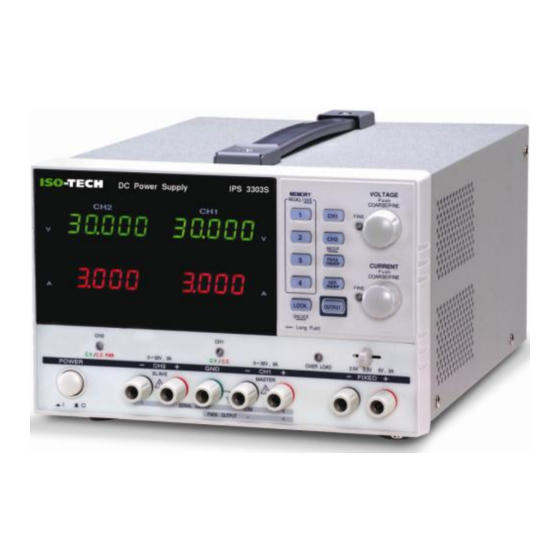
Page 1: Dc Power Supply
Instruction Manual IPS X303 Series DC Power Supply EN FR... -
Page 3: Table Of Contents
Table of Contents Table of Contents SAFETY INSTRUCTIONS ............5 OVERVIEW ................9 Introduction ............. 9 Series Lineup / Main Features ........ 11 Principle of Operation ..........12 CV/CC Crossover Characteristics ......14 FRONT AND REAR PANELS ............15 Front Panel Overview ..........15 Rear Panel Overview .......... - Page 4 IPS X303 Series Instruction Manual Command Syntax ........... 40 Error Messages ............. 41 Command List ............42 Command Details ........... 43 APPENDIX ................48 Fuse Replacement ..........48 SPECIFICATIONS ..............49 FAQ ..................52 INDEX ..................53...
-
Page 5: Safety Instructions
SAFETY INSTRUCTIONS SAFETY INSTRUCTIONS This chapter contains important safety instructions that you must follow when operating the IPS X303 series and when keeping it in storage. Read the following before any operation to insure your safety and to keep the best condition for the IPS X303 series. Safety Symbols These safety symbols may appear in this manual or on the IPS X303 series. - Page 6 IPS X303 Series Instruction Manual Safety Guidelines General Do not place any heavy object on the IPS X303 series. Guidelines Avoid severe impacts or rough handling that leads to damaging the IPS X303 series. CAUTION Do not discharge static electricity to the IPS X303 series. ...
- Page 7 SAFETY INSTRUCTIONS Operation Location: Indoor, no direct sunlight, dust free, almost non-conductive Environment pollution (note below) Relative Humidity: < 80% Altitude: < 2,000m Temperature: 0 to 40°C (Pollution Degree) EN 61010-1:2001 specifies the pollution degrees and their requirements as follows.
- Page 8 IPS X303 Series Instruction Manual Power cord for the United Kingdom When using the IPS X303 series in the United Kingdom, make sure the power cord meets the following safety instructions. NOTE: This lead/appliance must only be wired by competent persons WARNING: THIS APPLIANCE MUST BE EARTHED IMPORTANT: The wires in this lead are coloured in accordance with the following code: Green/ Yellow:...
-
Page 9: Overview
OVERVIEW OVERVIEW This chapter describes the IPS X303 series in a nutshell, including its main features and front / rear panel introduction. After going through the overview, follow the Setup chapter (page 20) to properly power up and set operation environment. Introduction Overview The IPS X303 regulated DC power supply series, are light weight,... - Page 10 IPS X303 Series Instruction Manual Constant Voltage/ Each output channel is completely transistorized and well-regulated, and Constant Current works in constant voltage (CV) or constant current (CC) mode. Even at the maximum output current, a fully rated, continuously adjustable output voltage is provided.
-
Page 11: Series Lineup / Main Features
OVERVIEW Series Lineup / Main Features Series Lineup Model V Meter A Meter USB Tracking Error ≤ 0.5% + 50mV of Master IPS 3303D 3 digit 3 digit ≤ 0.5% + 10mV of Master IPS 2303S 5 digit 4 digit ≤... -
Page 12: Principle Of Operation
IPS X303 Series Instruction Manual Principle of Operation Overview The power supply consists of the following. AC input circuit Transformer Bias power supply including rectifier, filter, pre-regulator and reference voltage source Main regulator circuit including the main rectifier and filter, series regulator, current comparator, voltage comparator, reference voltage amplifier, remote device and relay control circuit The block diagram below shows the circuit arrangement. - Page 13 OVERVIEW Current Limiter U104 acts as a current limiter. When the current is over predetermined rating, U104 is activated and decreases the current. U208 provides a reference voltage. U206 is the inverter amplifier. U103 is a comparator amplifier which compares reference voltage and feedback voltage, and then delivers to Q102, which then calibrates the output voltage.
-
Page 14: Cv/Cc Crossover Characteristics
IPS X303 Series Instruction Manual CV/CC Crossover Characteristics Background The IPS X303 series automatically switches between constant voltage mode (CV) and constant current mode (CC), according to load condition. CV mode When the current level is smaller than the output setting, the IPS X303 series operates in Constant Voltage mode. -
Page 15: Front And Rear Panels
CH4 CV/CC CH2 CV/CC/PAR CH1 CV/CC CH3 CV/CC Switch Indicator Indicator Indicator Indicator Display Displays output current of each channel. Volt Meter IPS 4303S: CH1/CH3 and CH2/CH4 IPS 2303S/3303S: CH1 and CH2 IPS X303S (5 digits) IPS 3303D (3 digits) - Page 16 IPS X303 Series Instruction Manual Amp Meter Displays output current of each channel. IPS 4303S: CH1/CH3 and CH2/CH4 IPS 2303S/3303S: CH1 and CH2 IPS X303S (4 digits) IPS 3303D (3 digits) Control Panel MEMORY RECALL / SAVE Memory Keys Saves or recalls panel settings. Four settings, 1 to 4, are available.
- Page 17 FRONT AND REAR PANELS Output Key Turns the output on or off. OUTPUT VOLTAGE Voltage Knobs Adjusts the output voltage level for the selected Push COARSE/FINE channel. Pressing the knob switches coarse and FINE fine level setting. CURRENT Current Knobs Adjusts the output current level for the selected Push COARSE/FINE...
- Page 18 IPS X303 Series Instruction Manual 30V , 3A Indicates CH2 Constant Voltage, Constant SLAVE CV/CC/PAR Current, or Tracking Parallel operation mode. C.V. C.C. PAR. Indicator CH2 Output Outputs CH2 voltage and current. SERIES 5V , 3A CH3 Overload Indicates CH3 Constant Voltage or Constant 10V , 1A Indicator Current state for the IPS 4303S.
-
Page 19: Rear Panel Overview
FRONT AND REAR PANELS Rear Panel Overview Power Cord / USB Connector Cooling Fan AC Selector Fuse Socket WARNING TO AVOID ELECTRIC SHOCK THE POWER CORD PROTECTIVE GROUNDING CONDUCTOR MUST BE CONNECTED TO GROUND. FOR CONTINUED FIRE PROTECTION. REPLACE FUSE ONLY WITH 250V FUSE OF THE SPECIFIED TYPE AND RATING. -
Page 20: Setup
IPS X303 Series Instruction Manual SETUP This chapter describes how to properly power up and configure the IPS X303 series before operation. Power Up Select AC voltage Before powering up the power supply, select the AC input voltage from the rear panel. Connect AC power Connect the AC power cord to the rear panel socket. -
Page 21: Load Cable Connection
SETUP Load Cable Connection GTL-104A 1. Turn the terminal counter-clockwise and loosen the screw. 2. Insert the cable terminal. 3. Turn the terminal clockwise and tighten the screw. GTL-105A Insert the plug into the socket. GTL-203A, 204A Insert the plug into the terminal. Wire type When using load cables other than the attached, make sure they have enough current capacity for minimizing cable loss and load line... -
Page 22: Output On/Off
IPS X303 Series Instruction Manual Output On/Off Panel operation Pressing the Output key turns on all channel OUTPUT OUTPUT outputs. The key LED also turns on. Pressing the Output key again turns the output and the key LED off. Automatic output Any of the following actions during output on automatically turns it off. -
Page 23: Switch Between Channels
SETUP Switch between channels Panel operation Switching between channels only applies to IPS 4303S. Press the CH1/3 key to toggle between CH1 and CH1/3 CH3. The active channel will be shown on the channel indicator. Press the CH2/4 key to toggle between CH2 and CH2/4 CH4. -
Page 24: Operation
IPS X303 Series Instruction Manual OPERATION CH1/CH2 Independent Mode Background / CH1 and CH2 outputs work independent of each other. Connection CH4 CH2 GND LOAD LOAD Output rating 0 to 30V / 0 to 3A for each channel Panel operation 1. - Page 25 OPERATION Note: this diagram shows non-European terminals. 3. Set the CH1 output voltage and current. Press (For CH1) the CH1 key (LED turns on) and then use the CH1/3 CH1/3 Voltage and Current knob. By default, the Voltage and Current knob work VOLTAGE CURRENT Push...
-
Page 26: Ch3 Independent Mode
IPS X303 Series Instruction Manual CH3 Independent Mode Background / For the IPS 3303S the CH3 rating is fixed at 2.5V/3.3V/5V, 3A. CH3 for Connection the IPS 4303S is variable: 0~5V,0~3A / 5.001~10V,0~1A . CH4 CH2 GND LOAD IPS 3303S:2.5V/3.3V/5V,3A (fixed) Output rating IPS 4303S:0~5V,0~3A / 5.001~10V,0~1A No Tracking... - Page 27 OPERATION 2.5V 3.3V , 3A 2. IPS 3303S: Select the output voltage, 2.5V/3.3V/5V using the CH3 voltage selector key. IPS 4303S: Press the CH1/3 key to switch to CH3 (The CH3 indicator will light). Use the CH1/3 voltage and current knobs to set the voltage and current.
-
Page 28: Ch4 Independent Mode
IPS X303 Series Instruction Manual CH4 Independent Mode Background / The IPS 4303S has a rating of 5V/1A max. Connection CH4 CH2 GND LOAD Output rating 5V/1A max No Tracking CH4 does not have tracking series/parallel mode. The CH4 output is not affected by CH1 and CH2 modes. -
Page 29: Ch1/Ch2 Tracking Series Mode
OPERATION CV → CC When the output value exceeds the set value, the C.V. C.C. C.V./C.C. indicator turns red. This indicates that CH3 has switched from constant voltage to constant current. C.V. C.C. CH1/CH2 Tracking Series Mode Background Tracking series operation doubles the Voltage capacity of the IPS X303 series by internally connecting CH1 (Master) and CH2 (Slave) in series and combining the output to a single channel. - Page 30 IPS X303 Series Instruction Manual 2. Connect the load to the front panel terminals, CH1+ & CH2− (Single supply). Note: this diagram shows non-European terminals. 3. Press the CH2 key (LED turns on) and then CH2/4 CH2/4 use the Current knob to set the CH2 output BEEP BEEP current to the maximum level (3.0A).
- Page 31 OPERATION C.V. C.C. PAR. C.V. C.C. Voltage level Double the reading on the CH1 Voltage meter. In the above case, the actual output is 20.0 x 2 = 40.0V. Current level CH1 meter reading shows the output Current. In the above case, 2.000A.
- Page 32 IPS X303 Series Instruction Manual 2. Connect the load to the front panel terminals, CH1+ & CH2−. Use the CH1 (−) terminal as the common line connection. Note: this diagram shows non-European terminals. 3. Press the CH1 key (LED turns on) and use the CH2/4 CH2/4 Voltage knob to set the master &...
- Page 33 OPERATION C.V. C.C. PAR. C.V. C.C. Master (CH1) CH1 meter reading shows the output voltage. In the voltage level above case, 20.0V. Master (CH1) CH1 meter reading shows the output current. In the current level above case, 2.000A. 7. Press the CH2 key (LED turns on) and use the CH2/4 CH2/4 Current knob to set the slave output current.
-
Page 34: Ch1/Ch2 Tracking Parallel Mode
IPS X303 Series Instruction Manual CH1/CH2 Tracking Parallel Mode Background / Tracking parallel operation doubles the current capacity of the IPS X303 Connection series by internally connecting CH1 and CH2 in parallel and combining the output to a single channel. CH1 controls the combined output. CH4 CH2 GND LOAD Output rating... - Page 35 OPERATION C.V. C.C. PAR. 4. The CH2 C.V./C.C. PAR. indicator turns red, indicating tracking parallel (PARA) mode. C.V. C.C. PAR. 5. Press the CH1 key (LED turns on) and then CH1/3 CH1/3 use the Voltage and Current knob to set the VOLTAGE CURRENT Push...
-
Page 36: Save/Recall Setup
IPS X303 Series Instruction Manual SAVE/RECALL SETUP Save Setup Background The front panel settings can be stored into one of the four internal memories. Contents The following list shows the setup contents. Independent / tracking series / tracking parallel mode ... -
Page 37: Recall Setup
SAVE/RECALL SETUP Recall Setup Background The front panel settings can be recalled from one of the four internal memories. Contents The following list shows the setup contents. Independent / tracking series / tracking parallel mode CH1/CH2 knob selection ... -
Page 38: Remote Control
IPS X303 Series Instruction Manual REMOTE CONTROL Remote Control Setup Background The IPS 3303D and IPS X303S are capable of being remotely controlled via the USB connection. Interface USB slave port, rear panel COM setting Set up the COM port inside the PC according to the following list. -
Page 39: Remote Connection Step
REMOTE CONTROL Remote Connection Step Entering the 1. Connect the USB cable to the slave port. remote control 2. The connection will be automatically established, and the front panel shows “USB…YES” message. mode 3. The power supply also automatically enters the lock state (the Lock key will become activated). -
Page 40: Command Syntax
IPS X303 Series Instruction Manual Command Syntax ISET<X>:<NR2>NL Command format 1: command header 2: output channel 3: separator 4: parameter 5: terminator(line feed) Output channel 1 (CH1) or 2 (CH2) Parameter Type Description Example <Boolean> Boolean logic 0 (off), 1 (on) <NR1>... -
Page 41: Error Messages
REMOTE CONTROL Error Messages The following error messages might appear when the IPS 3303D or X303S cannot accept the command. Message contents Descriptions Program mnemonic too The command length must be 15 characters or less. long Invalid character Invalid characters, such as symbols, are entered. Example: VOUT# Missing parameter The parameter is missing from the command. -
Page 42: Command List
Selects the operation mode. BEEP<BOOLEAN> Turn on or off the beep. OUT<BOOLEAN> Turn on or off the output. STATUS? Returns the IPS 3303D or IPS X303S status. *IDN? Returns the IPS 3303D or IPS X303S identification. RCL<NR1> Recalls a panel setting. SAV<NR1>... -
Page 43: Command Details
Minimum 10ms Example VSET1:20.345 Sets the CH1 voltage to 20.345V (for IPS X303S) VSET1:20.3 Sets the CH1 voltage to 20.3V (for IPS 3303D) VSET<X>? Description Returns the output voltage setting. 1: CH1, 2: CH2, (IPS 4303S: 3: CH3, 4: CH4) - Page 44 IPS X303 Series Instruction Manual IOUT<X>? Description Returns the actual output current. 1: CH1, 2: CH2, (IPS 4303S: 3: CH3, 4: CH4) Response time Minimum 10ms Example IOUT1? Returns the CH1 output current VOUT<X>? Description Returns the actual output voltage. 1: CH1, 2: CH2, (IPS 4303S: 3: CH3, 4: CH4) Response time Minimum 10ms...
- Page 45 REMOTE CONTROL STATUS? Description Returns the IPS 3303D or IPS X303S status. Response time Minimum 10ms Contents 8 bits in the following format Item Description 0=CC mode, 1=CV mode 0=CC mode, 1=CV mode 2, 3 Tracking 01=Independent, 11=Tracking series, 10=Tracking...
- Page 46 IPS X303 Series Instruction Manual BAUD<NR1> Description Sets the baud rate to 57600bps or 115200bps. <NR1> 0: 115200bps, 1: 57600bps Response time Minimum 10ms Example BAUD0 Sets the baud rate to 115200bps. LOCAL Description Exits remote mode and sets the instrument to local mode. Response time Minimum 10ms ERR?
- Page 47 REMOTE CONTROL HELP? Description Shows the command list. Response time Minimum 50ms Return parameters ISET<x>:<NR2> Sets the value of current. VSET<x>:<NR2> Sets the value of voltage. ISET<x>? Return the value of current. VSET<x>? Return the value of voltage. IOUT<x>? Returns actual output current, VOUT<x>? Returns actual output voltage.
-
Page 48: Appendix
IPS X303 Series Instruction Manual APPENDIX Fuse Replacement Steps 1. Take off the power cord and remove the fuse socket using a minus driver. 2. Replace the fuse in the holder. Rating 100V/120V:T6.3A/250V 220V/230V:T3.15A/250V... -
Page 49: Specifications
≤ 0.1% + 10mV of Master (0~30V) (No Load, with Tracking Operation Tracking Error load add load regulation≤100mV)) (IPS X303S) ≤ 0.5%+50mV of Master (IPS 3303D) Line: ≤ 0.01% + 3mV Parallel Load: ≤ 0.01% + 3mV (rating current ≤ 3A) Regulation Load: ≤... - Page 50 IPS 3303D 32V full scale, 3 digits 0.5" LED display IPS X303S 32V full scale, 5 digits 0.4" LED display Program Accuracy IPS 3303D Voltage: ± (0.5% of reading + 2digits) Current: ± (0.5% of reading + 2digits) IPS X303S Voltage: ±...
- Page 51 SPECIFICATIONS Options USB cable GTL-246 USB 2.0, A-B type...
-
Page 52: Faq
IPS X303 Series Instruction Manual Q1. I pressed the panel lock key but the output still turns on/off. A1. The output key is not affected by the panel lock key operation, for ensuring safety. Q2. The CH3 overload indicator turned on – is this an error? A2. -
Page 53: Index
INDEX INDEX automatic out off ........22 list of features ........11 banana plug ..........21 operation theory ........ 12 technology overview ......9 Baud rate load connection ......... 21 Remote control ......... 46 Local beep setting Remote control ......... 46 contents .......... - Page 54 IPS X303 Series Instruction Manual UK power cord ..........8 contact ..........52 status, instrument ........45 USB interface ..........38 Switch channels ........23 warning symbol ........... 5 wire, load ............ 21 tracking mode operation theory ........9...
- Page 55 INDEX Limited Warranty This meter is warranted to the original purchaser against defects in material and workmanship for 3 years from the date of purchase. During this warranty period, RS Components will, at its option, replace or repair the defective unit, subject to verification of the defect or malfunction.
- Page 56 IPS X303 Series Instruction Manual Africa Iso-Tech 1 & 2 Indianapolis Street Kyalami Business Park Kyalami, Midrand, South Africa Asia Iso-Tech 460 Alexandra Road, #15-01A PSA Building Singapore 119963 Europe Iso-Tech PO Box 99 Corby Northamptonshire NN17 9RS United Kingdom...
Need help?
Do you have a question about the IPS 3303D and is the answer not in the manual?
Questions and answers