Advertisement
Advertisement

Related Manuals for Adly Motor ATV-600

Summary of Contents for Adly Motor ATV-600
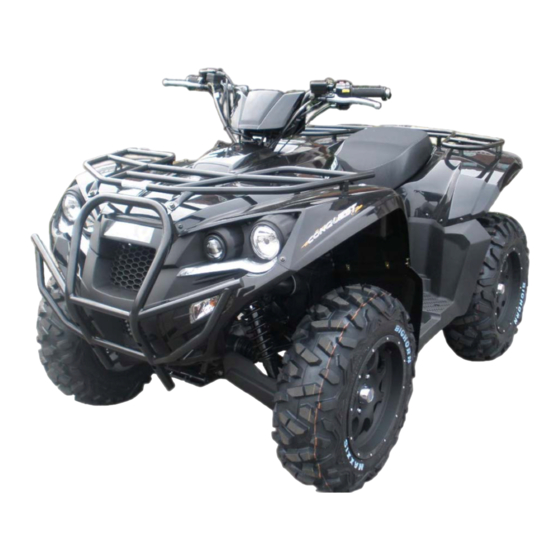
- Page 1 ATV-600 OWNER’S MANUAL...
- Page 2 It is our sincere wish that you enjoy operating the ATV-600 and receive fun from it. Should you have any problems, please feel free to contact our local dealer in your area.
-
Page 3: Table Of Contents
CONTENTS Page Foreword --------------------------------------------------------------------------------------------------------- 1 Operation Warning --------------------------------------------------------------------------------------------- 2 Safety Information ---------------------------------------------------------------------------------------------- 3 Specifications ---------------------------------------------------------------------------------------------------- 5 Periodical Check and Services ------------------------------------------------------------------------------ 7 Pre Operating Inspection -------------------------------------------------------------------------------------10 Operation -------------------------------------------------------------------------------------------------------- 13 Inspection and Maintenance -------------------------------------------------------------------------------- 29 Correct Way of Driving --------------------------------------------------------------------------------------- 47 Abnormalities and Trouble Shooting ---------------------------------------------------------------------- 49 VIN number and Identification ------------------------------------------------------------------------------ 50 Pre-Delivery Inspection ---------------------------------------------------------------------------------------51... -
Page 4: Operation Warning
OPERATION WARNING THIS VEHICLE IS NOT A TOY AND CAN BE HAZARDOUS TO OPERATE. NEVER OPERATE THIS VEHICLE WITHOUT PROPER INSTRUCTION. THIS VEHICLE IS NOT FOR YOUTH UNDER 16 YEARS OLD. ALWAYS WEAR A HELMET. AND PROTECTIVE CLOTHING. READ THIS OWNER’S MANUAL CAREFULLY. IT’S DANGEROUS TO DRIVE ON AN UNCLEAR ROAD CONDITION. -
Page 5: Safety Information
SAFETY INFORMATION Don’t allow your child to ride. Read all warning sticks on vehicle and follow the instruction. Keep a safe distance between your vehicle and other vehicles. Take a training course if you are a beginner. This vehicle is designed to be operated only on level, off road surfaces, free of obstacles. This vehicle is not equip with differential gears, do not make turns within high speed. - Page 6 SAFETY INFORMATION Clothing Actual weather condition should help you decide how to dress. However, it is important that the operator always protective clothing and apparel, including an approved helmet, eye protection, boots, gloves, long sleeved shift and pants. This type of clothing will provide you protection from some of the minor hazards you may encountered.
-
Page 7: Specifications
SPECIFICATIONS MODEL ATV-600 OVERALL LENGTH 2150 mm OVERALL WIDTH 1280 mm OVERALL HEIGHT 1250 mm WHEEL BASE 1320 mm NET WEIGHT 332 kg DISPLACEMENT 565 cc TYPE 4-stroke, 4V electroplated ceramic cylinder FUEL Unleaded (octane 90 or higher) COMPRESSION RATIO 10.2:1... - Page 8 SPECIFICATIONS 150cc (SAE 80 or SAE 90) FRONT DIFF. GEAR OIL 250cc (SAE 80 or SAE 90) REAR GEAR OIL H3 12V 55W x 2 / H7 12V 55W x 2 FRONT LIGHT BULB(HIGH / LOW) LED 12V 0.5W x 2 FRONT POSITION LIGHT BRAKE LIGHT BULB(TAIL LIGHT) 12V 5W / 21W x 2...
-
Page 9: Periodical Check And Services
PERIODICAL CHECK & SERVICES Maintenance Every Every Every Every 300km 4000km Remarks kilometer 500km 1000km 2000km Maintenance 1 Month 3 Month 6 Month 1 Year Check Item Interval Air cleaner element(Remark) Fuel filter Oil filter Replacement for every 1,000KM or 3 months Engine oil change Replacement for every 1,000KM or 3 months Tire and pressure... - Page 10 PERIODICAL CHECK & SERVICES Maintenance Every Every Every Every 300km 4000km Remarks kilometer 500km 1000km 2000km Maintenance 1 Month 3 Month 6 Month 1 Year Check Item Interval Throttle operation Engine bolt tightening CVT driving device(belt) CVT driving device(roller) Engine Drive Shaft Light/electrical equipment / multi-meters Fuel lines...
- Page 11 Remark: 1. Clean or replace the air cleaner element more often when the ATV in operated on dusty roads or in the heavily-polluted environment. 2. Maintenance should be performed more often when the ATV is operated in high speed and after the ATV has accumulated a higher mileage. 3.
-
Page 12: Pre Operating Inspection
PRE OPERATING INSPECTION Inspect your vehicle before you ride it. It only takes a few minutes to check and may save your life. Check the tires condition and pressure. Check the nuts, bolts and other fasteners. Check the drive chain condition and slack. Check the engine stop switch for good function. - Page 13 PRE OPERATING INSPECTION Check and Refueling Insert the key and turn to “OPEN” position for opening the fuel cap. After refueling, close the cap with key-on then turn the key to “LOCK” position. The key can be removed in “LOCK” position. Pull out the key and check fuel cap to make sure it’s locked.
- Page 14 PRE OPERATING INSPECTION Tire pressure : CAUTIONS Recommended tire pressure: 5 psi (35 kpa) Max. pressure : 3.8~5 psi (0.27~0.35 kgf/cm Min. pressure : 3.8~5 psi (0.25~0.35kgf/cm Maximum weight capacity : 560kg Do not over inflate the tire pressure as indicated on the tire. Check if there is any gravel in the tread grooves or any nail puncture.
-
Page 15: Operation
OPERATION Main Switch STEERING LOCK To turn off the engine. Press the key in OFF position and turn The key can be extracted. the key to left in order to lock the steering handle. To operate this function, the handle needs to turn to the left end. - Page 16 OPERATION Electric Starter Grip the brake lever then push the starter switch to cranks engine Use chock function when the weather is cold or difficult to start at beginning. : CAUTIONS Starter Switch When cranks the engine: Do not push down again the starter button as the engine is running.
- Page 17 OPERATION Recoil Starter The recoil starter is to start the engine when the battery power is low. Recoil Grasp the starter grip firmly, the pull it Puller out slowly approximately 4 in(100mm). Pull the grip up briskly and fully. ...
- Page 18 OPERATION Signal light switch Right signal light flashing indicates turning to the right. Left signal light flashing indicates turning to the left. Push switch to turn off lights. CAUTIONS: Always turn on signal lights before turning. Signal Switch Horn Button Turn on main switch and press down the horn button, the horn will sound.
- Page 19 OPERATION Electrical starter button This is a starting motor button for engine starting With the main switch “on”, press this button while holding the front or rear brake lever will start the engine. Headlight Switch Low beam -- For normal condition. High beam -- For farther lighting.
- Page 20 OPERATION Instrument Panel Temp. Warning RPM Warning Turn Indicator 2WD/4WD /LOCK Indication Engine Temp. Oil Warning High Beam Ind. Low Fuel Warning BAT. Power Low Fuel meter Speed Gear position Info. Display Disp. Selection...
- Page 21 OPERATION Steering Handle Lock The steering handle lock is located on the main switch. Turn the steering fully to the left. Insert the key into the main switch. Push the key then turn counter -clockwise to lock the steering. ...
- Page 22 OPERATION Gearshift Lever Parking (P) Low (L) Use to hold the vehicle in place when Use the position to get more power when parked or while starting the engine. climbing, dragging extra load, and for Whenever parking the ATV, apply the better acceleration.
- Page 23 OPERATION WARNING Improperly reverse operation could cause you to hit an obstacle or person behind you, resulting in serious injury. Make sure there are no obstacles or people behind you before selecting reverse gear. When it is safe to proceed, go slowly. ...
- Page 24 OPERATION Power supply There are 2 power supply sockets on the vehicle. One is attached to the right side of the body. Second socket is located inside of the storage box. You can use the accessory socket to power a warning light, spotlight, radio, or cell phone…...
- Page 25 OPERATION Front / Rear Brake Use front (right hand) and rear (left hand) wheel brakes simultaneously or foot brake when braking. Avoid unnecessary sudden braking as this may load to the wheels locking the ATV going out of control. ...
- Page 26 OPERATION Parking and Parking Brake Look for lever parking area. Make sure the ground surface is firm. After bringing your ATV to a stop, hold the brakes while you shift into PARK. Turn the ignition switch OFF. The parking brake lever is located on RELEASE LOCK the steering right hand.
- Page 27 OPERATION Engine Start-up & Cautions Check oil and fuel prior to start-up. 1. Set the gear to parking and throttle lever at the “close” state. 2. Use key to turn “Main Switch” on. 3. Pull break lever and push electric starter button. :...
- Page 28 OPERATION Fuel Meter The fuel meter is located on the right side of the instrument panel. When the tank is full, the level light bars are shows at top. During the fuel consuming, light bars decrease from top then down to bottom. It is recommend to added fuel when fuel meter symbol start to flash.
- Page 29 OPERATION Fuel Valve The fuel valve is located on the right side of the vehicle. With the valve turned to the ON position, fuel is supplied normally. When the main fuel supply runs out, it will be necessary to turn the valve to the RESERVE position.
- Page 30 OPERATION 2WD/4WD Select Switch The 2WD/4WD select switch is located above the throttle lever. 2WD is for normal driving condition. Press the 2WD/4WD select switch to use 4WD mode. The vehicle is equipped front differential. Slide the switch to “LOCK” position will lock the front differential.
-
Page 31: Inspection And Maintenance
INSPECTION AND MAINTENANCE Engine oil inspection and change Inspection Uses main parking brake to stand the ATV on the level ground, then run the engine for the 3~5 minutes and stop. Remove the dipstick and wipes the oil to count then inserts it to the engine again. (Do not rotate it.) Remove the dipstick and check whether oil level is in between the upper and... - Page 32 INSPECTION AND MAINTENANCE OIL CHANGE Change engine oil after the first 300km or first month, and change the engine oil every 1,000km or 3 months which comes first, clean oil filter after the first 300km or first month, and clean oil filter every 1,000km or 3 months. ...
- Page 33 INSPECTION AND MAINTENANCE Transmission Oil Inspection and Change Inspection: When ATV is stopped in the level ground, stop the engine and wait 3~5minutes. Check the transmission gear oil quantity by release the bolt and check from the hole. Front Diff. check bolt Front Diff.
- Page 34 INSPECTION AND MAINTENANCE Differential gear oil drain bolt Rear gear oil drain bolt The front differential oil drain bolt is located underneath the gear box. The rear gear box drain hole is located on the left side of the gear box. Differential gear oil infusion Final gear oil infusion ※...
- Page 35 INSPECTION AND MAINTENANCE Oil Filter Oil filter Remove the oil filter cartridge with an oil filter wrench. Apply a thin coat of engine oil to the o-ring of the new oil filter cartridge. Install the new oil filter cartridge with an oil filter wrench, and then tighten it to the specified torque with a torque wrench.
- Page 36 INSPECTION AND MAINTENANCE Checking the Spark Plug Remove the cap of spark plug. (remove the spark plug using the spark plug wrench in the tool kit.) Check the electrode if it is dirty or fouled by carbon deposits. Remove the carbon deposits on the electrode with steel wire, and clean the spark plug with gasoline, then, wipe dry with a rag.
- Page 37 INSPECTION AND MAINTENANCE Inspection of fuel level Uses main parking places stand ATV in the level ground, turn the main switch to “ON” position, check the speedometer fuel level. Fuel gauge may be defective or electric circuit disconnected. If the fuel meter does not move, please ride slowly to an authorized service station to have your ATV checked.
- Page 38 INSPECTION AND MAINTENANCE Battery This battery is located underneath the seat. Remove and Check Make sure the ignition switch OFF. Remove the seat. Remove the fix plate on the battery. Disconnect the negative (-) terminal lead from the battery first, then disconnect the positive (+) terminal lead.
- Page 39 INSPECTION AND MAINTENANCE Installation 1. Install the battery in reverse order of removal. 2. Check all bolts and other fasteners are secured. NOTICE: Keep the ATV battery clean. If the battery’s posts are corroded and/or are covered with white powder clean them with water.
- Page 40 INSPECTION AND MAINTENANCE Coolant Maintaining the coolant will allow the cooling system to work properly and prevent freezing, overheating, and corrosion. Coolant system inspection 1. Stops ATV in the level place. 2. Check reserved tank from viewing window to see if coolant lever is between the upper limit and lower limit mark.
- Page 41 INSPECTION AND MAINTENANCE Replenishment of coolant Always keep radiator cap tightly closed. 1. Support vehicle on a level ground. 2. Remove the maintenance cover. Open reserved tank cap, refill coolant until reaches the limits. If coolant level becomes too low and occurs too often, it may indicate there is something wrong with the coolant system.
- Page 42 INSPECTION AND MAINTENANCE A reference table for anti-freeze concentration percentages under different temperatures 1. Radiator anti-freezer shall use ASTM or SAE approved type. (ADLY radiator agent) 2. Proper anti-freeze percentages for different frozen temperatures are as follows. anti-freeze percentages Frozen temperature Remark 50% concentration is used for all ATV before delivery to...
-
Page 43: Idle Speed Adjustment
INSPECTION AND MAINTENANCE Seat Removal Pull the seat release knob located underneath the left hand side of rear cover. Then lift the seat and pull to rear. Idle Speed Adjustment The screw to adjust engine idle speed is under the seat in front of the air cleaner box. - Page 44 INSPECTION AND MAINTENANCE Air Cleaner Element 5xRetainer clips Disassembly: 1. Remove the seat, 5 retainer clips on air cleaner cover, and then remove filter element. 2. Take the element out and clean it. (Refer to maintenance schedule.) Assembly: Assembly the air cleaner in reverse order of disassemble. Before put the filter element, please add about 10g SAE30 oil on the element to keep the ability of filtering.
- Page 45 INSPECTION AND MAINTENANCE Parking Brake Adjustment Look for lever parking area. Turn the ignition switch OFF. If the parking brake does not functioning will, adjust the nuts in 2 locations. Adjust nut on the parking lever base. Adjust nut on the parking brake caliper. If it is necessary to start the engine when your ATV is stopped on a grade in gear, rock the vehicle back and froth to allow shifting...
- Page 46 INSPECTION AND MAINTENANCE Brake Fluid Check Stop the ATV in the level ground, then check the brake fluid level. The brake fluid reservoir is location on L/R brake master cylinder assembly and foot brake. (Replenishment of brake fluid) 1. Loosen the screws and remove the master cylinder cover. 2.
- Page 47 INSPECTION AND MAINTENANCE Fuse Fuse box is under the seat. Remove the seat and you can see the fuse box is on the right side. Turn off ignition switch, and check fuses if they are intact. Replace the blown fuse with a new one having the same specified amperage rating (30A or 15A or 10A).
- Page 48 INSPECTION AND MAINTENANCE Tool kit This tool bag is in the front storage box. The tools in the kit set are sufficient to perform routine maintenance and simple repairs. The tools kit includes the following items. ※ Standard / Phillips screwdriver ※...
-
Page 49: Correct Way Of Driving
CORRECT WAY OF DRIVING Start of Driving Turn on the key switch and start-up the engine. Release the parking brake. Hold the brake while change the gear into the desired position. Press the throttle lever slowly to control your speed. Acceleration is to increase the speed. - Page 50 CORRECT WAY OF DRIVING Stop of the Vehicle Approaching to the parking point: Release the throttle lever and apply both front and rear wheel brakes while the vehicle is stopped. Complete stop: Stop the engine by turn off the main switch. Do not park on uneven ground to avoid tipping over.
-
Page 51: Abnormalities And Trouble Shooting
ABNORMALITIES AND TROUBLE SHOOTING If the engine fails to start or engine fails to keep running. Check the gas tank is fuel are available and sufficient. Whether the procedure for engine start up is correct. Try to diagnose these malfunctions yourself first. Contact the local dealer as soon as possible for checking on any abnormality of your vehicle. - Page 52 VIN NUMBER AND IDENTICIFICATION Please record the VIN and engine number for further reference. The frame number (VIN) is stamped on the front The engine number is engraved on middle top of right side of frame. right crankcase. FRAME NO. RFL ENGINE NO.
-
Page 53: Pre-Delivery Inspection
P.D.I. (Pre-Delivery Inspection) 1. Record the frame and engine number into the owner’s manual. 2. Check that all tires have correct pressure specified in the owner’s manual. 3. Engine oil ( 4 stroke, SAE10W/40 or Grade SAE40 ) is enough. ... -
Page 54: Maintenance And Service Record
MAINTENANCE AND SERVICE RECORD P.D.I. 500 KM 1,000 KM NOTES:________________ NOTES:________________ NOTES : ________________ _______________________ _______________________ _______________________ _______________________ _______________________ _______________________ _______________________ _______________________ _______________________ _________________________ _________________________ _________________________ DEALER: DEALER: DEALER: _________________________ _________________________ _________________________ DATE: DATE: DATE: 2,000 KM 3,000 KM 4,000 KM NOTES:________________ NOTES:________________ NOTES : ________________... - Page 55 MAINTENANCE AND SERVICE RECORD 5,000 KM 6,000 KM 7,000 KM NOTES:________________ NOTES:________________ NOTES : ________________ _______________________ _______________________ _______________________ _______________________ _______________________ _______________________ _______________________ _______________________ _______________________ _________________________ _________________________ _________________________ DEALER: DEALER: DEALER: _________________________ _________________________ _________________________ DATE: DATE: DATE: 8,000 KM 9,000 KM 10,000 KM NOTES:________________ NOTES:________________...
- Page 56 MAINTENANCE AND SERVICE RECORD 11,000 KM 12,000 KM 13,000 KM NOTES:________________ NOTES:________________ NOTES : ________________ _______________________ _______________________ _______________________ _______________________ _______________________ _______________________ _______________________ _______________________ _______________________ _________________________ _________________________ _________________________ DEALER: DEALER: DEALER: _________________________ _________________________ _________________________ DATE: DATE: DATE: 14,000 KM 15,000 KM 16,000 KM NOTES:________________ NOTES:________________...
-
Page 57: Abnormalities Service Record
ABNORMALITIES SERVICE RECORD ODOMETER : KM ODOMETER : KM ODOMETER : NOTES:________________ NOTES:________________ NOTES : ________________ _______________________ _______________________ _______________________ _______________________ _______________________ _______________________ _______________________ _______________________ _______________________ _________________________ _________________________ _________________________ DEALER: DEALER: DEALER: _________________________ _________________________ _________________________ DATE: DATE: DATE: ODOMETER : KM ODOMETER : KM ODOMETER : NOTES:________________ NOTES:________________... - Page 58 ABNORMALITIES SERVICE RECORD ODOMETER : KM ODOMETER : KM ODOMETER : NOTES:________________ NOTES:________________ NOTES : ________________ _______________________ _______________________ _______________________ _______________________ _______________________ _______________________ _______________________ _______________________ _______________________ _________________________ _________________________ _________________________ DEALER: DEALER: DEALER: _________________________ _________________________ _________________________ DATE: DATE: DATE: ODOMETER : KM ODOMETER : KM ODOMETER : NOTES:________________ NOTES:________________...
- Page 59 This page is officially blank...
Need help?
Do you have a question about the ATV-600 and is the answer not in the manual?
Questions and answers
Mi sa aprins o pipetă de ulei in bord ce înseamnă și **** o sting?
If the oil warning light is blinking on an Adly ATV-600, it indicates a potential issue related to the engine oil. Even if the oil and filter have been changed and the oil level is correct, a blinking oil light may suggest the maintenance interval needs to be reset properly or there may be an issue with the oil pressure sensor or system.
This answer is automatically generated