Table of Contents
Advertisement
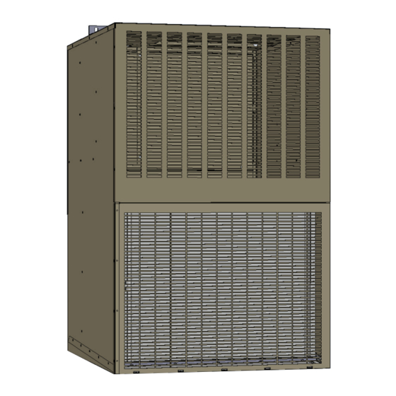
Thru-the-Wall Packaged Heating & Cooling Units
Installation
Guide
Comfort Pack
Universal Series
This unit should
be installed in an
OUTSIDE WALL FOR
THRU-THE-WALL
INSTALLATION ONLY!
Please read the entire installation guide before starting the installation.
A Division of National Refrigeration & Air Conditioning Products, Inc.
539 Dunksferry Road • Bensalem, PA 19020 • (215) 244-1400 • 1-800-523-7138 • Fax: (215) 639-1674
80%
THERMAL
EFFICIENCY
National Comfort Products
NATIONAL
COMFORT
PRODUCTS
HEATING & A/C EQUIPMENT
CPG
U-Models
Gas
Heating
Electric
Cooling
®
®
Advertisement
Table of Contents

Related Manuals for National Comfort Product CPG41238-U Series

Summary of Contents for National Comfort Product CPG41238-U Series
- Page 1 NATIONAL ® COMFORT PRODUCTS HEATING & A/C EQUIPMENT Thru-the-Wall Packaged Heating & Cooling Units Installation Guide Comfort Pack Universal Series This unit should be installed in an OUTSIDE WALL FOR THRU-THE-WALL INSTALLATION ONLY! U-Models Heating Electric THERMAL EFFICIENCY Cooling Please read the entire installation guide before starting the installation. National Comfort Products ®...
-
Page 2: Table Of Contents
Table of Contents Safety First ............page 3-4 Start up ......... . page 20-21 Before You Start ........... -
Page 3: Safety First
Installation Guide for Comfort Pack (CPG) Units Safety First! HAZARD INTENSITY LEVELS WARNING 1. DANGER: FAILURE TO COMPLY WITH WILL RESULT IN SEVERE THE UNIT MUST BE PERMANENTLY GROUNDED. FAILURE TO DO SO CAN PERSONAL INJURY OR DEATH AND/ OR PROPERTY DAMAGE. CAUSE ELECTRICAL SHOCK RESULTING IN SEVERE PERSONAL INJURY OR DEATH. -
Page 4: Before You Start
Installation Guide for Comfort Pack (CPG) Units Safety First! WARNING WARNING THESE INSTRUCTIONS ARE INTENDED AS AN AID TO QUALIFIED, If any of the original wire as supplied with the furnace must be replaced, LICENSED SERVICE PERSONNEL PROPER INSTALLATION, it must be replaced with wiring material having a temperature rating of at ADJUSTMENT OPERATION THIS... - Page 5 Installation Guide for Comfort Pack (CPG) Units THE CHASSIS BASE AND EVAPORATOR DRAIN PAN, NOT CAUTION BY USING REFRIGERANT PIPING OR THE OUTDOOR FAN MOUNT. THE BOTTOM OF THE CHASSIS IS NOT SMOOTH AND WILL DAMAGE FLOORS IF SLID. installation this appliance must...
-
Page 6: Installation
Installation Guide for Comfort Pack (CPG) Units Be sure that the electrical service provided to the building can enough to allow for return air provisions to the unit. To reduce handle the load imposed by the unit. the possible transmission of sound and vibration, a resilient material such as rubber or cork should be installed between the IMPORTANT —... -
Page 7: Clearances
Installation Guide for Comfort Pack (CPG) Units Clearances Secondary Drain Trap Install Instructions: 1. The trap and 3” piece of clear flexible 1/2” ID tubing are For proper unit performance and maximum operating life please maintain the following minimum installation clearances. shipped loose to prevent damage. -
Page 8: Unit Location Considerations
Installation Guide for Comfort Pack (CPG) Units Unit Location Considerations 6. If the unit is mounted behind a decorative grille, one or both of the following items must be done to eliminate recirculation of air to the unit: n thru-the-wall installation, due to the various types of wall construction, it is not possible to provide detailed instructions. -
Page 9: Vent Termination Clearances
Installation Guide for Comfort Pack (CPG) Units Vent Termination Clearances for Direct Vented Installations in the USA For other gas venting information see page 7. Balcony - with perpendicular side wall Inside Corner Detail Combustible & Noncombustible X = 24” (610 mm) Z = 20”... -
Page 10: Electrical
Installation Guide for Comfort Pack (CPG) Units Electrical a. Line Voltage Connections b. Connect the single phase power supply to unit fuse All wiring must be installed in accordance with applicable blower terminal L1 and L2 codes. c. Connect ground wire to lug The unit is factory wired for 230/1/60 power. -
Page 11: Electrical
Installation Guide for Comfort Pack (CPG) Units High Voltage Power Supply Install a separate disconnect WARNING switch at the location of the through the wall unit. LIVE ELECTRICAL COMPONENTS! During installation, testing, servicing and troubleshooting of this product, it may be necessary to work with live electrical components. - Page 12 Installation Guide for Comfort Pack (CPG) Units DSI Control Identification FAN OUTPUT- FAN OUTPUT- INDUCER FAN INPUT COOLING HEATING RELAY NEUTRALS SPARK IGNITOR OUTPUT 24VAC, 60Hz., .5A MAX. MOLEX TO ANSI Z21.20 AUTOMATIC HEAT COMPONENTS VOLTAGE COMMON EXTENDED FAN TIME VOLTAGE DIP SWITCH SECONDARY...
-
Page 13: Dimensions
Installation Guide for Comfort Pack (CPG) Units Comfort Pack Dimension Drawing Note: Unit must be mounted a minimum of 8” above finished floor. 20 1/8" 31 7/16" 28" 1 3/32" 7 11/16" 3 3/4" 15 13/16" 11 1/16" Patch Plate Junction Box 26 9/32"... -
Page 14: Gas Furnace Specifications
Installation Guide for Comfort Pack (CPG) Units Gas Furnace Specifications Sequence of Operations (Gas Heat) Gas Heat – The cabinet includes a gas furnace with integral 1. Call for Heat – The thermostat sends a call for heat therefore flue duct, direct spark ignition, safety controls, and operating energizing the “white”... -
Page 15: Abnormal Functions
Installation Guide for Comfort Pack (CPG) Units Abnormal Functions Installation Codes • Interrupted Thermostat Call for Heat – If the thermostat These units must be installed in accordance with local demand for heat is removed before the flame is recognized, the building codes. - Page 16 Installation Guide for Comfort Pack (CPG) Units Instructions for Changing Pressure Switch NOTE: THIS ADJUSTMENT CAN ONLY 1. Open the burner/control compartment access panel. Locate BE DONE AFTER THE HEATER IS IN the pressure switch. OPERATION. IT IS INCLUDED IN THE STARTUP PROCEDURES 2.
-
Page 17: Gas Piping, Venting & Pressures
Installation Guide for Comfort Pack (CPG) Units Clearances Pressure Testing Supply Piping Clearance to combustibles is defined as the minimum distance Test Pressures Above 1/2 PSI: Disconnect the heat manual valve from a heater to a surface or object that is necessary to ensure from the gas supply line that is to be tested. - Page 18 Installation Guide for Comfort Pack (CPG) Units Valve Outlet Gas Pressure Setting WARNING Measuring valve outlet gas pressure cannot be done until the heater is in operation. Normally adjustments should not be necessary to the factory preset regulator (also, see paragraph on ALL COMPONENTS OF A GAS SUPPLY high altitude operation).
-
Page 19: Ignition System
Installation Guide for Comfort Pack (CPG) Units adjustment is necessary, set pressure to correct settings the gas valve, the venter motor goes through a 45-second post- by turning the regulator screw IN (clockwise) to increase purge and the fan motor remains energized for an additional pressure. -
Page 20: Start Up
Installation Guide for Comfort Pack (CPG) Units Flame Rollout Switch 6. Verify that the return air duct connection is physically sound, sealed to the unit cabinet and terminates outside of the space containing the furnace. All units are equipped with a temperature activated manually reset 7. -
Page 21: Special Notes For Extremely Cold Weather Areas
Installation Guide for Comfort Pack (CPG) Units 7. Turn on the electric power to the heater. 8. Set the thermostat to the desired setting. WHAT TO DO IF YOU SMELL GAS... • Thermostat calls for heat, energizes venter motor. • Venter pressure switch closes, firing the unit. •... -
Page 22: Gas Control Valve
Installation Guide for Comfort Pack (CPG) Units Figure 4: Gas Control should be taken to prevent possible vent system ice blockage that could result in safety shutdown of the burners: 1. Adjust to the highest achievable temperature rise within the rise and static pressure ranges specified on the rating plate. - Page 23 Installation Guide for Comfort Pack (CPG) Units unit and take it to a work area. Spare chassis are recommended WARNING so that extensive servicing can be performed outside the living space. This will prevent introducing dirt or doing damage in the living area, and could help to eliminate significant disruption of the air conditioning and heating functions in the living areas.
- Page 24 Installation Guide for Comfort Pack (CPG) Units Inspect the Heat Exchanger • Check the vent system for soundness. Replace any parts that do not appear sound. • Check the wiring for any damaged wire. Replace damaged Remove the heat furnace baffle panel (see page 28). Remove any wiring.
- Page 25 Installation Guide for Comfort Pack (CPG) Units Figure 6B Inspect and Clean the Burner Secondary Air Shield Assembly With the burner assembly removed, shine a flashlight on the w/ End Cap Removed burner ribbons. Look for carbon buildup, scale, dust, lint, and/ Upper Burner Brackets or anything that might restrict flow through the spaces between the burner ribbons.
-
Page 26: Gas Valve
Installation Guide for Comfort Pack (CPG) Units Figure 7 1. Turn off the gas and disconnect the electric power. 2. Open the burner/control compartment access panel. 3. Disconnect the three venter motor wires at their terminal block connections. 4. Holding the motor, remove the three screws that attach the venter motor mounting plate to the venter housing. -
Page 27: Slide Out Furnace Instructions
Installation Guide for Comfort Pack (CPG) Units Pressure Switch Do not attempt to repair the DSI integrated control module; the only field replaceable component is the fuse. If it is determined that the pressure switch needs replacing, use only the factory-authorized replacement part that is designed for CONTROL this heater. - Page 28 Installation Guide for Comfort Pack (CPG) Units 2. Remove the patch plate 3. Remove (2) right side screws and remove the front furnace baffle. Gas Line Front Furnace Baffle Power Cord Gas Line Power Cord Pull Forward 4. Unplug (2) molex plugs before sliding out the heat exchanger/ furnace assembly.
-
Page 29: Equipment Specifications
Installation Guide for Comfort Pack (CPG) Units CPG - ELECTRICAL DATA INDOOR MINIMUM MAXIMUM OUTDOOR TOTAL MODEL VOLTAGE COMPRESSOR BLOWER CIRCUIT OVERCURRENT FAN MOTOR AMPS MOTOR AMPACITY PROTECTOR CPG41238-U*** 208-230/60/1 26.0 10.3 12.8 CPG41838-U*** 208-230/60/1 44.0 13.1 16.3 CPG41851-U*** 208-230/60/1 44.0 13.1 16.3... -
Page 30: Air Flow
Installation Guide for Comfort Pack (CPG) Units Check Your Temperature Rise AS CLOSE AS POSSIBLE TO THE EVAPORATOR COIL BEHIND THE FILTER DOOR *Example shown has a ducted return The temperature rise should be as follows 38MBTU = 52.5°F Nominal (45°F to 60°F) 51MBTU = 55°F Nominal (45°F to 65°F) 64MBTU = 67°F Nominal (60°F to 80°F) In order to calculate CFM use the formula... - Page 31 Installation Guide for Comfort Pack (CPG) Units Comfort Pack Gas CFM and Temperature Rise 38,000 BTU Input UNIT SIZE COLOR SPEED .1" w.c. ∆T .2" w.c. ∆T .3" w.c. ∆T .4" w.c. ∆T .5" w.c. ∆T 36.1 36.6 37.0 38.8 41.4 Yellow 39.4...
- Page 32 Installation Guide for Comfort Pack (CPG) Units COMFORT PACK - CFM (w/ Dry Coil) UNIT SIZE COLOR SPEED 0.1” w.c. 0.2” w.c. 0.3” w.c. 0.4” w.c. 0.5” w.c. Yellow CPG412 Blue Black Orange Yellow CPG418 Blue Black Orange Yellow CPG424 Blue Black Orange...
-
Page 33: Wiring Diagram
Installation Guide for Comfort Pack (CPG) Units... - Page 34 Installation Guide for Comfort Pack (CPG) Units...
- Page 35 Installation Guide for Comfort Pack (CPG) Units DSI INTEGRATED CONTROL MODULE CONTROL GREEN LED STATUS STEADY ON Normal operation, no call for heat FAST FLASH Normal operation, call for heat 1 FLASH In lockout from failed ignition or flame loss 2 FLASH Pressure switch does not close within 30 seconds 3 FLASH...
- Page 36 Installation Guide for Comfort Pack (CPG) Units TROUBLE SHOOTING TROUBLSHOOTING PROBLEM PROBABLE CAUSE REMEDY No power to unit Turn power, check supply fuses or circuit breaker Venter motor will not start No 24 volt power to integrated circuit board. Turn up thermostat; check control transformer output Integrated circuit board fuse blown.
-
Page 37: Replacement Parts Guide
Installation Guide for Comfort Pack (CPG) Units Replacement Parts Guide To assure accurancy in providing the correct parts, please provide the unit model designation and serial number with the parts order. The model designation breakdown is shown below: PARTS CABINET ITEM DESCRIPTION PART NO. - Page 38 Installation Guide for Comfort Pack (CPG) Units Replacement Parts Guide (Continued) CHASSIS CHASSIS ITEM DESCRIPTION PART NO. MODEL ITEM DESCRIPTION PART NO. MODEL Air Divider 14256109D CP41.0-U1.0 Outdoor Coil Mount 14256113 Base 14256642 Indoor Coil Cover 14256117 Indoor Coil 14208305 Indoor Coil Drain Pan 14256173 Outdoor Coil...
- Page 39 Installation Guide for Comfort Pack (CPG) Units IMPORTANT!!! BEFORE REMOVING A WARRANTY COMPRESSOR, PLEASE FILL OUT THE FOLLOWING AND CALL (800) 523-7138. REMOVAL OF COMPRESSOR WITHOUT FACTORY VERIFICATION CAN LEAD TO WARRANTY CREDIT BEING DENIED Incoming Voltage to Compressor at Contactor is:__________Volts Compressor Starting AMP Draw:__________ Ω...
- Page 40 Installation Guide for Comfort Pack (CPG) Units NATIONAL ® COMFORT PRODUCTS HEATING & A/C EQUIPMENT A Division of National Refrigeration & Air Conditioning Products, Inc. 539 Dunksferry Road | Bensalem, PA 19020 | 215-244-1400 | 1-800-523-7138 | Fax: 215-639-1674 COMFORT PACK LIMITED WARRANTY 1.
- Page 41 Installation Guide for Comfort Pack (CPG) Units The term “consequential damages” shall include, but not be limited to, loss of anticipated profits, business interruption, loss of use, revenue, reputation and data, costs incurred, including without limitation, for capital, fuel, power and loss or damage to capital or equipment.
-
Page 42: Warranty
Installation Guide for Comfort Pack (CPG) Units ENGINEERING SPECIFICATION GUIDE 1. Product Name Slide Out Furnace (Gas) National Comfort Products – Comfort Pack Serviceable slide out gas furnace assembly with stainless steel heat exchanger. 2. Manufacturer Sequencing Control (Electric) National Comfort Products Two stage heat sequencing triac control board. -
Page 43: Notes
Installation Guide for Comfort Pack (CPG) Units Notes... - Page 44 NATIONAL ® COMFORT PRODUCTS HEATING & A/C EQUIPMENT National Comfort Products A Division of National Refrigeration and Air Conditioning Products, Inc. 539 Dunksferry Road • Bensalem, PA 19020-5908 (800) 523-7138 • Fax (215) 639-1674 www.NationalComfortProducts.com Manual-Installation Guide Comfort Pack CPG 14299126 12/2016...
Need help?
Do you have a question about the CPG41238-U Series and is the answer not in the manual?
Questions and answers