Table of Contents
Advertisement
Quick Links
Newport Medical Instruments, Inc.
Newport e360 Ventilator
Operating Manual
OPR360US Rev. H
For Model e360S-US
07/11
Newport Medical Instruments, Inc.
1620 Sunflower Ave.
Costa Mesa, CA 92626
Tel: 1.714.427.5811
Tel: 1.800.451.3111 (USA Only)
Fax: 1.714.427.0489
Customer Service ext. 282
www.ventilators.com
0344
email: Info@ventilators.com
Advertisement
Table of Contents

Subscribe to Our Youtube Channel
Related Manuals for Newport e360


Summary of Contents for Newport e360
- Page 1 Newport Medical Instruments, Inc. Newport e360 Ventilator Operating Manual For Model e360S-US OPR360US Rev. H 07/11 Newport Medical Instruments, Inc. 1620 Sunflower Ave. Costa Mesa, CA 92626 Tel: 1.714.427.5811 Tel: 1.800.451.3111 (USA Only) Fax: 1.714.427.0489 Customer Service ext. 282 www.ventilators.com 0344 email: Info@ventilators.com...
- Page 2 Manual Revision History Rev A April 2004 New release Rev B July 2006 Update to software USR1.1 Rev C February 2008 Update company logo and remove CE/EU representative information Rev D March 2008 Update manual to include Addendum Document (DOC360-ADD-4-US) for software release USR3.1 Rev E May 2008...
- Page 3 © Copyright 2011 Newport Medical Instruments, Inc. All rights reserved. The Newport e360 Ventilator system is manufactured in accordance with Newport Medical Instruments, Inc. proprietary information. The Newport e360 is covered under patent # 6,439,229. The information in this manual is the sole property of Newport OPR360U A0509 Medical Instruments, Inc.
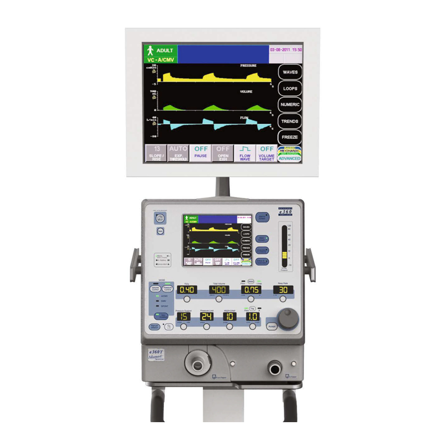
- Page 4 USB Connection Remote Alarm Connection Cooling Fan Alarm Speaker Equipotential Ground Stud External Alarm Silence AC Power Connection On/Off Power Switch Fuse Drawer RS232 Connection External Battery Connection Figure F-2: Newport e360 Rear Panel Figure F-3: GUI Navigation Map OPR360US H0711...
- Page 5 ADULT 05-01-2008 15:30 Hours 999999.7 VTPC-SPONT Check power on). Do not use a test lung to block the patient wye for the circuit check test. OPR360US H0711...
-
Page 6: Device Description
Table of Contents Introduction Device Description Intended Use Information About this Manual Typing Conventions Software Versions Service Guidelines Regular Service Complete Service Records Disclaimers Warnings General Warnings Filter Warnings Power Supply Warnings Gas Warnings Auxiliary Equipment Warnings Cautions Warranty Information Responsibility for Patient Safety Limitation of Liability Overview... - Page 7 Table of Contents Unpacking, Assembly, and Safety Check Unpack the Ventilator List of Package Contents Assembly Exhalation Valve Compartment Connect Air, Oxygen and AC Power Install the Breathing Circuit System Safety Check Procedure Setup and Inspection Emergency Intake Valve Circuit Check Gas Supply Alarms AC Power Loss/Battery Backup Alarm High/Low Airway Pressure Alarm/Circuit Disconnect Alarm/...
- Page 8 Table of Contents Screen Files Event History Files Ventilator Controls Guide Ventilator Settings in Advanced Data Set Slope/Rise Expiratory Threshold Pause Flow Waveform Volume Target Open Exhalation Valve Inspiratory and Expiratory Hold Maneuvers P0.1 Measurement Function Negative Inspiratory Force (NIF) Maneuver Waves and Loops Display Adjusting Scale Auto Scale...
-
Page 9: Cleaning And Maintenance
Table of Contents Cleaning and Maintenance Introduction Use of Filters Inspiratory (To Patient) Port Expiratory (From Patient) Port Disassembly and Reassembly Procedures Rear Panel Fan Filter Exhalation Manifold Exhalation Flow Sensor Exhalation Valve Inspiratory Manifold Oxygen Sensor Fuses Cleaning Sterilizing Autoclave Sterilization EtO Sterilization Guide to Cleaning and Sterilizing... -
Page 10: Specifications
Alarms Settings in NIV Specifications Alarms, Controls, Monitored Data, Setup & Calibration Physical Specifications Foldout Diagrams Front e360 Ventilator System and Accessories e360 Rear Panel Graphical User Interface (GUI) Navigation Map Control (Front) Panel Circuit Check Screen Rear Main Screen... - Page 11 Section 1: ntroduction...
-
Page 12: Table Of Contents
Section 1: ntroduction Device Description ..........1-1 Intended Use Information ......1-2 About this Manual ..........1-2 Typing Conventions ..........1-3 Software Versions ..........1-4 Service Guidelines ..........1-4 Regular Service ........... 1-4 Complete Service Records ......1-4 Disclaimers ............1-4 Warnings ............1-5 General Warnings .........1-5 Filter Warnings .......... - Page 13 Introduction Device Description The e360 Ventilator is a high performance ventilator that is easy to use and maintain. The e360 features a dual servo gas delivery system, a servo controlled active exhalation valve, a simple to use interface and a touch screen graphics monitor. The electronically-controlled inlet gas...
-
Page 14: Intended Use Information
The e360 Ventilator System is for use by prescription only. Only those who are professional healthcare providers with training in the use of this ventilator system and experience with providing ventilator support should use it. -
Page 15: Typing Conventions
Section 7- Explanation of Modes, Breath Types and Special Functions This is the “how does it work” reference section of the manual to give you a general description of the e360 breath types, modes and special functions. Section 8- Specifications This is where you will find ranges, physical dimensions, and information about settings, controls, alarms, and displays. -
Page 16: Software Versions
Disclaimers Newport Medical has no responsibility for the safe operation of the e360 Ventilator System if the intended use, intended user, and intended use environment requirements specified in this document are not followed. Newport Medical has no responsibility for the safe operation of the... -
Page 17: Warnings
Ventilator is in use on a patient. Have an alternate method of oxygen monitoring with high and low alarms available for use when using the e360, in the event the built-in oxygen monitor is unavailable due to a disabled, defective or missing oxygen sensor. -
Page 18: Filter Warnings
The regularly scheduled maintenance should only be done by a qualified service technician using the e360 Ventilator Service Manual. Filter Warnings At all times during patient use, keep clean, dry filters in the following locations to protect the patient and the ventilator: 1. -
Page 19: Power Supply Warnings
Introduction Do not submerge filters in liquids of any kind. Between uses, reusable filters must be steam autoclaved and then checked for resistance, according to the manufacturer’s instructions. Power Supply Warnings To maintain grounding integrity, connect the ventilator only to a hospital-grade receptacle. -
Page 20: Gas Warnings
Oxygen source gas must be medical grade, 100% oxygen. Auxiliary Equipment Warnings Newport Medical cannot warrant or endorse the safe performance of third party humidifiers for use with the e360 Ventilator. Contact the manufacturers/distributors of third party humidifiers about the compliance and performance characteristics of their products. -
Page 21: Warranty
Please register your ventilator online at www.ventilators.com. Warranty The Newport e360 Ventilator System is warranted to be free of defects for a period of two (2) years from invoice date of purchase. The following are exceptions to this warranty: •... -
Page 22: Responsibility For Patient Safety
The above is the sole warranty provided by Newport Medical. No other warranty expressed or implied is intended. Representatives of Newport Medical are not authorized to modify the terms of this warranty. Federal Law and Regulations in the United States and Canada restrict this device to sale by or on the order of a physician. -
Page 23: Limitation Of Liability
Newport Medical shall not be liable for, nor shall the buyer be entitled to recover, any special incidental or consequential damages or any liability incurred by buyer to any third party in any way arising out of or relating to the goods. - Page 24 Section 2: verview...
-
Page 25: Table Of Contents
Section 2: verview Ventilator System Overview ........2-1 Control Panel Layout and Labeling ......2-1 Graphical User Interface Display (GUI) and Controls ..............2-1 Navigation Map for GUI Menus ......2-1 Lower Front Panel Layout ........2-1 Rear Panel Layout ..........2-2 Navigating the Control Panel ........2-2 Using Touch - Turn - Accept ......2-2 Selecting Mandatory Breath Type &... -
Page 26: Ventilator System Overview
When there is a difference between the measured value and the target value, e360 adjusts gas delivery so that the target value is achieved. The system uses two gas modules. When air and... -
Page 27: Rear Panel Layout
15 seconds before powering ON the ventilator. Navigating the Control Panel Refer to Foldout F-4 for a full view of the e360 Control Panel functions described here. OPR360U A0509... -
Page 28: Selecting Mandatory Breath Type & Mode
To activate the NIV function in any mode or breath type, press the Non Invasive button (the indicator will light) and then press Accept. Non Invasive always reverts to OFF when e360 is powered down (the setting is not retained). See Section 7 for more information on Non Invasive function. -
Page 29: Patient Triggering Methods
Overview Patient Triggering Methods Refer to Foldout F-4, item 8. The ventilator offers the clinician the choice of flow or pressure (P) triggering for patient-initiated breaths in all modes of ventilation. To select Flow or P, press the Trig button (LED lights) and then press Accept. -
Page 30: Alarm Silence Button
Overview (3 min) Button Refer to Foldout F-4, item 11. Press the O (3 min) button to start a timed delivery of 100% oxygen, regardless of the current F setting. The indicator on the O min) button lights when this function is activated. F returns to the set value and the indicator turns off after three minutes or when the button is pushed a second time, whichever comes first. -
Page 31: Main Screen
Overview Main Screen Refer to Foldout F-4, item 6. Press the Main Screen menu button on the Control Panel to reveal five GUI menu buttons: Waves, Loops, Numeric, Trends and Freeze. When Freeze is selected the Adjustment knob will move a cursor across the screen and display data and time relevant to the point the cursor is crossing. -
Page 32: Internal Battery
After 10 seconds the hour meter will disappear. Internal Battery The e360 Ventilator is equipped with an internal battery that when fully charged can support approximately one hour of ventilator function at the following settings: Adult, SIMV with RR 15, V 500, t insp 1.0 seconds, F... - Page 33 AC power) after a 5 hour charge on AC power, the internal battery may need to be replaced. The standard replacement schedule for the e360 internal battery is every 24 months. Refer to the e360 Ventilator Service Manual for replacement procedure.
- Page 34 Section 3: npacking, Assembly, and Safety Check...
- Page 35 Section 3: npacking, Assembly, and Safety Check Unpack the Ventilator and Accessories ....3-1 List of Package Contents ......3-1 Assembly ..............3-1 Exhalation Valve Compartment ....3-5 Connect Air, Oxygen and AC Power... 3-5 Install the Breathing Circuit System ..3-6 Safety Check Procedure ........3-8 Setup and Inspection ........
- Page 36 • Accessory Basket for Cart Assembly Refer to Foldout F-1 or Figure 3-1 for complete view of e360 assembled on the cart. 1. Set aside the disposable breathing circuit filters and store the spare exhalation flow sensor in a convenient location.
- Page 37 Unpacking, Assembly, and Safety Check OPR360U A0509 Figure 3-1 Mounting Accessories to Cart OPR360US H0711...
- Page 38 Unpacking, Assembly, and Safety Check Figure 3-2 External Monitor OPR360U A0509 5. Optional: Install External Monitor (instructions are provided with the monitor). See Figure 3-2. OPR360US H0711...
- Page 39 Unpacking, Assembly, and Safety Check Main Screen Extended Functions Setup & Calibration F O2 Tidal Volume Flow I Insp Resp Rate A/CMV A/CMV A/CMV Pressure Support Pressure Limit PEEP/CPAP Flow Manual Inflation Inactive Manual Accept Inflation Figure 3-3 Mounting Expiratory Filter Heater 6.
- Page 40 Unpacking, Assembly, and Safety Check Exhalation Valve Compartment Open the Exhalation Valve Compartment and check to make sure that the exhalation valve and flow sensor are fitted securely. See Figure 3-4. Close the compartment door. Refer to Section 6 for removal and cleaning instructions.
- Page 41 Unpacking, Assembly, and Safety Check Figure 3-6 Air, O and AC Power Connections Ensure that the AC power cord is connected to the fitting on the back of the ventilator. Tighten the retaining clamp as needed to secure the cord. See Figure 3-6, B. Caution Periodically inspect the air and oxygen inlet water traps and drain water from the bowls as necessary by pressing the pin at the bottom of the bowl.
- Page 42 Patient connection Figure 3-9 Non-heated Breathing Circuit with HME OPR360U A0509 NOTE: The e360 can be used with a reusable or disposable two limb breathing circuit. No proximal line or external exhalation valve is required. WARNING! Do not use electronically conductive breathing circuits.
- Page 43 Use the e360 Safety Check Record at the end of this section to record the results of each check. Do not use the e360 ventilator if it does not pass the Safety Check Procedure. Setup and Inspection 1.
- Page 44 Circuit Check 1. Connect the high pressure oxygen and air hoses from the oxygen and air inlet water traps on the back of the Newport e360 to 50 ± 10 psig gas sources provided by gas cylinders, wall outlets or air compressor.
- Page 45 Int Battery (Internal Battery) indicator lights and the message AC Power Loss Battery Back Up appears in the window. The e360 issues a short beep every five (5) minutes while running on internal battery.
- Page 46 Unpacking, Assembly, and Safety Check 8. Press the Reset button to clear the High Paw alarm message and visual indicators. Minute Volume / Back Up Ventilation / Apnea Alarms 1. Adjust the Resp Rate to 20 b/min. Verify that both audible and visual indicators for High MV (Exhaled Minute Volume) alarms are activated within 30 seconds.
- Page 47 Shut Down Alarm 1. Switch the e360 power to OFF. Verify that the audible Shut Down alarm activates. 2. Press the Alarm Silence button. Verify that the alarm is silenced.
- Page 48 NOTE: Make copies of this form to record the results of safety checks. Newport e360 Ventilator Safety Check Record Newport Medical recommends that you perform a complete Safety Check prior to A) The initial use of the ventilator; and, B) At least at every Preventative Maintenance interval.
- Page 49 Section 4: etting Up For Patient Use...
- Page 50 Section 4: etting Up For Patient Use Power Conditions ..............4-1 Shutdown Alarm ............4-1 Overview: Preparing For Patient Ventilation ....4-1 Setup & Calibration Menu ........... 4-2 Circuit Check ............4-2 Oxygen and Flow Sensors ........4-3 Exhalation Flow Sensor, Calibration ....4-3 (Oxygen) Sensor, Calibration ......4-4 Sensor, Disable ..........4-4 Patient Setup .............4-5...
- Page 51 Ventilation Controls Guide ..........4-8 Ventilation Settings in Advanced Data Set ...... 4-10 Slope/Rise ..............4-10 Expiratory Threshold ..........4-10 Pause ................ 4-10 Flow Waveform ............4-10 Volume Target ............4-10 Open Exhalation Valve ..........4-10 Inspiratory and Expiratory Hold Maneuvers ....4-10 P0.1 Measurement .............
- Page 52 OFF. Cancel the Shutdown alarm by pressing the Alarm Silence button. NOTE: Make sure that the e360 is completely shutdown before the power switch is turned on again. If the power switch is turned off and then on too quickly and the screen does not load correctly, turn the power off and wait 15 seconds before powering ON the ventilator.
- Page 53 Setup & Calibration menu screens. Circuit Check Refer to Foldout F-5. The Circuit Check is available in Standby condition after the e360 is turned ON. It requires that the e360 be connected to a compressed air gas source. Perform the Circuit Check: •...
- Page 54 Setting Up For Patient Use a. Confirm the integrity and tightness of connections for all breathing circuit components such as tubing, filters and humidifier chamber, as well as the exhalation valve components. b. Repeat the test. 7. The results of the Circuit Check are logged in the Event History. NOTE: Circuit Check function is only available in the standby condition.
- Page 55 NOTE: The Exhalation Flow Sensor Calibration is automatically performed as part of the Circuit Check. Make sure to perform the Circuit Check each time you set up the e360 Ventilator for patient use. (Oxygen) Sensor, Calibration Refer to Figure 4-1.
- Page 56 Setting Up For Patient Use To Disable the O Sensor 1. Touch the Sensors button, then touch the O Sensor button. 2. Touch Disable to disable the O sensor, then touch Yes to confirm. 3. Touch Exit. Figure 4-2. Basic Data Set Bar indicating that the O sensor and F alarms are disabled...
- Page 57 Leak Comp (Leak Compensation) Select Leak Comp ON or OFF. When Leak Compensation is turned ON, the e360 automatically adjusts the bias flow between 3 and 8 L/min for Ped/Infant selection and 3 and 15 L/min for Adult, in order to maintain an end expiratory base flow of 3 L/min.
- Page 58 Comm (Communication) Protocol Select the RS232 communication protocol that corresponds with the monitoring system that is connected to the e360 Ventilator. Touch the button to select from Newport, Newport 2, and Vuelink. Contact Newport Technical Service for more details regarding the communication port protocol.
- Page 59 Setting Up For Patient Use NOTE: See “Save Feature” and “Download Feature” on following pages in this section for details on saving Screen and Event History files. Ventilation Controls Guide The following table shows the ventilation parameters that are active in each mode/breath type.
- Page 60 Setting Up For Patient Use WARNING! Always ensure that ventilator settings that are not in use (their displays are dimmed) are set at appropriate, safe levels in case of accidental breath type or mode changes. NOTE: When Freeze is activated, the Freeze button turns to “Start” and all other menu buttons are dimmed and not functional until Start is pressed.
- Page 61 1. Press the Extended Functions menu button. 2. Touch and hold the Insp Hold button on the right of the display. The e360 will perform the hold and measure the static pressure. The maneuver is terminated by releasing your finger from the button or when 15 seconds elapse.
- Page 62 Setting Up For Patient Use The Mechanics data set will show Plateau Pressure, Total PEEP, Static Compliance, Inspiratory and Expiratory Resistance. If the maneuver does not succeed in providing a stable static pressure (patient effort is present) or other exclusion criteria is not met, the related calculated values will not be displayed.
- Page 63 Ventilation continues per user settings. • Backup ventilation is disabled for one minute. • When the e360 detects a patient trigger, it imposes a 100 millisecond delay before delivering inspiratory flow to the patient. • Normal operation resumes after the first patient trigger or after one minute if no trigger is detected.
- Page 64 (See Figure 4-5) 4. Touch and hold the NIF (menu button) to perform the maneuver. The e360 will temporarily cease all flow delivery while the button is being touched. 5. Upon release of the NIF button, choose the ideal NIF value by using the adjustment knob to move the cursor to the appropriate point on the pressure waveform.
- Page 65 Setting Up For Patient Use Explanation of NIF Maneuver Function Conditions After the NIF Measurement is turned ON the following condition occurs; • Ventilation continues according to user settings but a 3-minute timing window opens within which the user may touch the NIF button.
- Page 66 Setting Up For Patient Use Adjusting Scale To adjust scales: Touch the GUI screen at the X or Y axis of the desired scale to be adjusted. A blue indicator bar appears on the screen to identify the parameter selected for scale change. Use the Adjustment knob to increase or decrease the scale and press the Accept button to confirm the change.
- Page 67 Setting Up For Patient Use Event History Screen Refer to Foldout F-9 From the Extended Functions menu touch the Event History button to access the Event History Log. This log records the 1000 most recent occurrences of alarm violations and settings, ventilator setting changes, sensor calibration results and power On/Off sequences with the date and time of each event.
- Page 68 Numeric screen files. Trends Screen The e360 ventilator can display two trends screens, each screen displays four trended parameters containing up to 24 hours of trended data. Touch the Trends button from the Main Screen menu to choose between the two trend screens.
- Page 69 Setting Up For Patient Use Data Sets Refer to Figure 4-7 Figure 4-7 Data Sets Selected sets of data may be viewed on the GUI during ventilation utilizing the Data Sets button at the bottom of the GUI screen. Three different monitored data subsets and one settings subset are accessed by touching the tabs at lower right corner of the display.
- Page 70 A maximum of 200 Screen or Event (and Alarm) History files can be saved. After 200 of either type are saved, the OPR360U A0509 oldest file is deleted. When the Save function is complete, e360 emits a short, two-tone beep. 4-19 OPR360US H0711...
- Page 71 Setting Up For Patient Use Waves, Loops, Trends, Numeric and Extended Functions Screens (see Figure 4-7) Touch the “Freeze” button. “Save” and “Start” buttons will appear. Touch the “Save” button to store the screen image or touch the “Start” button to exit the Freeze screen and resume normal plotting. Figure 4-7 Waveform Save and Start Buttons Alarm Setting Screen Touch the Save button to store a screen image of the current alarm settings.
- Page 72 Setting Up For Patient Use Download Feature Touching Screen Files and Event History Files buttons on the Technical screen allows retrieval and downloading of the stored images and spreadsheet files to an external flash drive via the USB port on the rear of the ventilator (See Figure 4-8). 1.
- Page 73 Section 5: larms...
- Page 74 Section 5: larms Introduction ............5-1 Visual Alarm Displays ..........5-1 360˚ Alarm Lamp ..........5-1 Alarm and Message Display ......5-1 Device Alert LED ..........5-2 GUI Alarms Screen Environment ......5-3 Alarm Settings Screen ........5-3 Saving the Alarm Settings Screen ..... 5-3 Ajustable Alarms .........
- Page 75 The 360˚ Alarm Lamp Refer to Foldout F-4, item 4. Located at the top center of the e360 front panel, the 360˚ Alarm Lamp flashes yellow and/or red when an alarm is violated. The lamp remains lit in a steady state to show a latched alarm until the Reset button is pressed.
- Page 76 Alarms Disconnect as well as all messages are displayed in the center section of the status bar in the Graphical User Interface (GUI). These messages flash while active then remain in a steady state (latched) after the alarm violation has been corrected until the Reset button is used to clear the alarm.
- Page 77 Alarms WARNING! If a Device Alert alarm occurs, ventilation ceases and the emergency intake relief valve and exhalation valve opens. GUI Alarms Screen Environment Alarm Settings Screen See Figure 5-1 or Foldout F-8. Press the Alarms Screen menu button to open the Alarm Settings screen on the GUI.
- Page 78 Alarms Figure 5-2 Alarm History Log Saving the Alarm History Log See Figure 5-2. Touch the Save Alarm History button to save the Alarm History Log for later download as a spreadsheet file in comma-separated format (.csv). Refer to Section 4 for instructions on downloading files that are saved to memory.
- Page 79 Alarms Alarm Tones See Figure 5-4. Touch the Alarm Tones button to open the screen. Use the Adjustment knob to select one of three unique sets of sounds that will be activated when an alarm is violated. Press Accept to confirm the change. Figure 5-4 Alarm Tones Exiting Alarm Screens Touch any menu button on the control panel to exit any alarm screen.
- Page 80 Alarms Suction Disconnect Feature Press and hold the Alarm Silence button for one second or longer (until the ventilator sounds a short tone) to enable the Suction Disconnect feature. With this feature enabled the ventilator will automatically silence all patient and disconnect alarms, display the message Ventilation Suspended, disable automatic leak compensation, and deliver a bias flow of 10 L/min for Adult or 5 L/ min for Ped/Infant patient types if the ventilator senses that the...
- Page 81 Alarms Alarm Violation and Remedy Guide The following table lists alarm and informational messages alphabetically. The alarm priority, type (ventilator/patient problem differentiation), violation message or criteria (what causes the alarm to be activated) and remedy (possible corrective actions) are included in this guide.
- Page 82 Alarms Alarm or • Priority Description Device Alert • Type and/or Remedy Message • Lamp Color Criteria Check patient. Evaluate settings/readjust as necessary. Check trigger sensitivity. Check that the breathing circuit is intact and securely connected. The alarm is recovered •...
- Page 83 Alarms Alarm or • Priority Description Device Alert • Type and/or Remedy Message • Lamp Color Criteria Contact a qualified service representative to replace • Medium vent fan. Check Vent Fan inside of • Ventilator the unit fails. • Yellow NOTE: Message cannot be cleared with the Reset button.
- Page 84 Alarms Alarm or • Priority Description Device Alert • Type and/or Remedy Message • Lamp Color Criteria Check patient and provide an alternate source of • High Control CPU Control CPU ventilation. • Device Alert Failed Failure • Red Contact a qualified service representative.
- Page 85 Alarms Alarm or • Priority Description Device Alert • Type and/or Remedy Message • Lamp Color Criteria Check patient and provide Ventilator Device Alert an alternate source of malfunction. (If message ventilation. Also activated display is if less than possible) If the alarm is due to 10% of the Unsilence-...
- Page 86 Calibrate the O sensor O2 Low • Ventilator inactive if the by pressing the O 3 min • Red e360 detects a button or by accessing O disabled or Sensor calibration button defective in Setup & Calibration. oxygen sensor, or oxygen...
- Page 87 Alarms Alarm or • Priority Description Device Alert • Type and/or Remedy Message • Lamp Color Criteria Sensor is disconnected Check flow sensor from cable. connection and recalibrate. Ventilator is • High Flow Sensor unable to • Ventilator Clean or replace sensor Error calibrate the •...
- Page 88 Alarms Alarm or • Priority Description Device Alert • Type and/or Remedy Message • Lamp Color Criteria A High Paw Make sure exhalation alarm violation valve is functioning terminates the correctly. current breath Evaluate ventilator settings • High and cycles to and readjust if necessary.
- Page 89 Alarms Alarm or • Priority Description Device Alert • Type and/or Remedy Message • Lamp Color Criteria in an inspiratory time greater than 5 seconds, Insp Time • Medium including any and Pause settings and Too Long • Ventilator pause time, so readjust as necessary.
- Page 90 Alarms Alarm or • Priority Description Device Alert • Type and/or Remedy Message • Lamp Color Criteria NOTE: The ventilator continues to operate normally until the battery is depleted, at which time a Device Alert alarm occurs. capacity has • High Low Battery dropped WARNING! To ensure...
- Page 91 Alarms Alarm or • Priority Description Device Alert • Type and/or Remedy Message • Lamp Color Criteria Set Low Paw Change alarm limit to Low Paw Informational Alarm level is greater than the set PEEP Below PEEP Message less than set level.
- Page 92 Alarms Alarm or • Priority Description Device Alert • Type and/or Remedy Message • Lamp Color Criteria Random Access Memory • High that is used Monitor RAM • Device Alert by the monitor Failed (cont.) • Red processor on the main PCB is damaged.
- Page 93 Alarms Alarm or • Priority Description Device Alert • Type and/or Remedy Message • Lamp Color Criteria Reconnect the O sensor. The O Sensor Informational NOTE: Always use an Sensor is Disconnect Message external O monitor with disconnected. alarms while ventilating with this message.
- Page 94 Alarms Alarm or • Priority Description Device Alert • Type and/or Remedy Message • Lamp Color Criteria (The e360 may have been powered by the Power • High internal battery Failure • Device Alert until it was (cont.) • Red...
- Page 95 Alarms Alarm or • Priority Description Device Alert • Type and/or Remedy Message • Lamp Color Criteria WARNING! Ventilation and triggering are suspended, the exhalation valve and the Sustained emergency High • High relief valve open Baseline • Ventilator as needed for Pressure •...
- Page 96 Section 6: leaning and Maintenance...
- Page 97 Section 6: leaning and Maintenance Introduction ................6-1 Use of Filters ................. 6-1 Inspiratory (To Patient) Port ........6-1 Expiratory (From Patient) Port ......... 6-1 Disassembly and Reassembly Procedures ....... 6-2 Rear Panel Fan Filter ..........6-2 Exhalation Manifold ..........6-3 Exhalation Flow Sensor ........6-3 Exhalation Valve ...........6-5 Inspiratory Manifold ..........
- Page 98 Gas that enters the Expiratory (From Patient) Port on the ventilator from the breathing circuit may be moist and contain pathogens. Newport Medical strongly recommends the use of a dry, clean filter in this location for three reasons: 1. To protect the expiratory manifold from potential contaminants in exhaled gases;...
- Page 99 The following diagram and instructions are for removal and reinstallation of the fan filter. 1. Gently pry the fan cover from the back panel of the e360 (a coin can be used). 2. Remove the fan filter from the cover.
- Page 100 Cleaning and Maintenance Figure 6-1 Fan Filter Exhalation Manifold Exhalation Flow Sensor The following diagram and instructions are for the removal and reinstallation of the exhalation flow sensor. 1. Open the front panel door on the lower left front of the ventilator to expose exhalation valve and flow sensor.
- Page 101 Cleaning and Maintenance Figure 6-3 Remove Flow Sensor 3. Disconnect the flow sensor cable from the plastic body of the sensor by pulling the cable connector straight out. Do not twist. 4. To reconnect the cable connector to the sensor body: Take care to line up the notch in the cable connector with the notch in the connector on the sensor body.
- Page 102 Cleaning and Maintenance and will depend on observance of safe handling precautions and the ability to calibrate the sensor. Always make sure that the flow sensor is completely dry before installation. Exhalation Valve The following diagram and instructions are for removal and reinstallation of the exhalation valve.
- Page 103 Cleaning and Maintenance Figure 6-6 Exhalation Valve Assembly Caution Proper orientation of the various components is critical. Failure to reassemble the exhalation valve correctly will result in leaks in the exhalation system. 7. To re-assemble and reinstall the valve, reverse these steps taking care to align the guide pin on the valve cap with the slot in the valve body See Figure 6-7.
- Page 104 Cleaning and Maintenance Inspiratory Manifold The following diagram and instructions are for removal and reinstallation of the inspiratory manifold. 1. Using a flat screwdriver or a coin, unscrew the two screws on the lower right front panel section and remove it to expose the inspiratory manifold.
- Page 105 The following diagram and instructions are for the removal and reinstallation of fuses. The fuses are located in the top of the AC power module on the rear of the e360. 1. Set the power switch to the OFF position and disconnect the OPR360U A0509 ventilator from AC power and gas supplies.
- Page 106 Cleaning and Maintenance Figure 6-10 Remove Fuses 4. Reinstall the fuse drawer. NOTE: Refer to the e360 Ventilator Service Manual for fuse specifications. Cleaning Definition of clean: the removal of all foreign material (for example, soil or organic matter) from objects. Cleaning is normally accomplished by washing with running water, mechanical action, or enzymatic products.
- Page 107 Cleaning and Maintenance Caution Do not sterilize the entire ventilator. Standard sterilization techniques, including EtO and formalin, may cause damage. NOTE: Follow the cleaning and sterilization instructions provided by the manufacturer of each assembly as well as your facility’s policy. Autoclave Sterilization: 1.
- Page 108 Cleaning and Maintenance Ventilator/ Cleaning and Sterilization Additional Component Methods Information Accessory e360 fan filter Wash filter in mild detergent Replace if solution, rinse thoroughly, allow damaged. to air dry. Inspiratory filter Single patient use: discard. Replace with each Expiratory filter Reusable: dry, then autoclave.
- Page 109 Monitor for water accumulation, drain and panel air and clean as necessary. Replace the bowl if oxygen high there is any sign of wear/damage. If inlet...
- Page 110 Newport whichever parts authorized service technician following comes first the instructions found in the e360 Ventilator Service Manual. Discard and replace the Oxygen (O Every 2 Sensor every two years or when the years or as...
- Page 111 Caution Do not store the ventilator on its side or back. Repackaging the Ventilator Use the original packing carton and material to ship the ventilator, or contact your Newport representative to order replacement packing material. See Contact Information at the front of this manual. OPR360U A0509...
- Page 112 Section 7: xplanation of Modes, Breath Types and Special Functions...
- Page 113 Section 7: xplanation of Modes, Breath Types and Special Functions Introduction ..............7-1 Settings Functions ............7-1 Timing Limitations to Ventilation Controls ....7-1 Control Retention ............7-1 Control Range ............. 7-1 Mandatory Breath Types ..........7-1 Volume Control ............7-2 Pressure Control ............
- Page 114 Control Retention All ventilation control settings, except Noninvasive and Scale setting, are retained when e360 is powered OFF. When the ventilator is powered ON, the control settings that are retained in memory are the initial Start Ventilating ventilation and alarm settings unless the user selects new settings.
- Page 115 Explanation of Modes, Breath Types and Special Functions Mandatory Control Panel Advanced Advanced Breath Type Selection Selection- Selection- Open Exhalation Volume Target Pressure Pressure Control Control Volume Volume Target Control or Pressure Pressure Control Control (VPTC) Biphasic Pressure Pressure Control Release (BPRV) Table 7-1 Control Selections for Mandatory Breaths...
- Page 116 When Open Exhalation Valve is ON, the e360 Ventilator actively controls the exhalation OPR360U A0509 valve so that excess pressure is vented out, the degree of pressure overshoot is minimized and airway pressure is maintained close to the target pressure.
- Page 117 Spontaneous Breath Management in SIMV and SPONT Modes There are two forms of spontaneous breath assistance on the e360 ventilator in SIMV and SPONT modes, Pressure Support and Volume Target Pressure Support.
- Page 118 Explanation of Modes, Breath Types and Special Functions patient spontaneous efforts that trigger the ventilator, e360 delivers breaths with a constant pressure equal to PEEP/CPAP + Pressure Support until the end of patient inspiration which is determined by the attainment of one of the three cycling off thresholds. The breaths are delivered according to the user-selected settings for Pressure Support, Slope/Rise, and PEEP/CPAP.
- Page 119 Explanation of Modes, Breath Types and Special Functions spontaneous breaths in the Volume Targeted Pressure Control SPONT and SIMV modes, the ventilator delivers breaths with a constant pressure in the breathing circuit at a pressure equal to a ventilator selected level between PEEP/CPAP + 5 cmH O/mbar and the pressure limit, until the end of patient inspiration which is determined by the attainment of one of the three cycling off...
- Page 120 If the patient doesn’t breathe or if the patient’s efforts don’t cause airway pressure or airway flow to reach the Trig threshold, the e360 Ventilator delivers the number of time-triggered breaths each minute selected via the Resp Rate setting.
- Page 121 Explanation of Modes, Breath Types and Special Functions In SIMV, mandatory and spontaneous breaths may be delivered to the patient. The user may choose to Pressure Control, Volume Control, Biphasic Pressure Release or Volume Target Pressure Control the mandatory breaths. Mandatory breaths may be time or patient-triggered.
- Page 122 Advanced Features & Special Functions Bias Flow When e360 is in standby or ventilating condition, it provides 3 L/ min of mixed-gas (when both air and oxygen source gases are connected) Bias Flow during the exhalation period. Exceptions to this Bias Flow level are described below.
- Page 123 The Leak Comp (Automatic Leak Compensation/ Baseline Pressure Management) function allows the user to select whether or not they want the e360 to compensate for leaks over and above the 3 L/min bias flow. Leak Comp is factory preset to ON and the selection is retained after power down.
- Page 124 Non Invasive Ventilation (NIV) The e360 Ventilator can be used for invasive (intubated patient) or noninvasive (mask) ventilation. When the Non Invasive button is activated on the front panel (LED lights), e360 tailors the ventilator’s...
- Page 125 Section 8: pecifications...
- Page 126 Section 8: pecifications Alarms, Controls, Monitored Data, Setup & Calibration .. 8-1 Physical Specifications ............. 8-18 OPR360U A0509...
- Page 127 Specifications Alarms, Controls, Monitored Data, Setup & Calibration Table 8-1 Location and/or Range and Resolution or Item Function Description GUI- For any message not shown here All Other Informational refer to Section 5, Alarms for more Messages Message information. Alarm History GUI-Alarms See Event History Range: 1 to 10 (55 - 75 dbA)
- Page 128 Specifications Location and/or Range and Resolution or Item Function Description Changing any ventilation setting that affects mode, breath timing, flow/volume, pressure, or trigger Back Up sensitivity suspends back up Ventilation ventilation for 60 seconds. It is also (BUV) suspended for 60 seconds following (Results from Suction Disconnect function with low MVE Alarm...
- Page 129 4. Test Lung = no humidification, no heat. NOTE: Circuit Type selection affects the accuracy of monitored values for expiratory flow, expiratory tidal volume and expiratory minute volume. Range: Newport, Newport 2, Vuelink Comm. Allows user to select protocol to GUI-Technical Protocol communicate with patient monitoring systems via the RS232 port.
- Page 130 Specifications Location and/or Range and Resolution or Item Function Description Data Read Software type is read invalid from both Alarms-Non Failure Contact the EEPROM on the main board and a Adjustable Service Alarm stored file on the compact flash card. LED on Control Panel lights (if possible).
- Page 131 Specifications Location and/or Range and Resolution or Item Function Description Contains a list of the last 200 saved Event and Alarm History logs (.csv files). Files are assigned an 8-digit file Event History GUI-Technical name that includes a letter for file type Files (H for history, etc), the last 4 digits of the serial number, and a 3 digit...
- Page 132 Specifications Location and/or Range and Resolution or Item Function Description Freeze: Suspends plotting of graphs (waveforms, loops, or trends) and GUI-Main holds the current display for extended Freeze/Start/ and Extended viewing. Save Functions Start: Resumes plotting of graphs. Save: Captures current screen image for later downloading.
- Page 133 Specifications Location and/or Range and Resolution or Item Function Description Ideal Body GUI-Patient Range: 2-2202 lb (1-999 kg) Weight Setup Range: Up to 15 seconds Generates an Inspiratory Hold Inspiratory GUI-Extended maneuver at the end of a mandatory Hold Functions breath inspiration for as long as the button is pushed.
- Page 134 Specifications Location and/or Range and Resolution or Item Function Description When the monitored proximal pressure </= low baseline pressure Low Baseline Alarms-Non criteria for more than 0.5 seconds for Pressure Adjustable two consecutive breaths. Accuracy: ±1 cmH O/mbar Unsilenceable audible alarm sounds Alarms-Non Low Battery when internal battery capacity has...
- Page 135 Specifications Location and/or Range and Resolution or Item Function Description Ped/Inf: 0.00 to 9.99 L (resolution 0.01 L) Adult: 10.0 to 99.9 L (resolution 0.1 L) Accuracy: ±10% or ±0.3 L, whichever (cont.) is greater NOTE: The display will not be updated if the exhalation flow sensor is disconnected.
- Page 136 Specifications Location and/or Range and Resolution or Item Function Description When pressed delivers 100% oxygen for 3 minutes. Pressing button again 3 Min Control Panel turns off 100% oxygen delivery. Indicator lights when O 3 min is in effect. Can perform an oxygen sensor calibration by delivering 100% oxygen Sensor GUI-Sensors...
- Page 137 Specifications Location and/or Range and Resolution or Item Function Description Range: Ped/Infant: 0 to 30 cmH O/mbar PEEP/CPAP (resolution 1 cmH O/mbar) (Baseline Control Panel Adult: 0 to 45 cmH O /mbar Pressure-Set) (resolution 1 cmH O/mbar) Accuracy: ±10% or ±1 cmH O/mbar, whichever is greater.
- Page 138 Specifications Location and/or Range and Resolution or Item Function Description Pressure Bar Displayed range: –10 to 120 cmH Control Panel Graph mbar Range: Ped/Infant: 0 to 70 cmH O/mbar (resolution 1 cmH O/mbar) Pressure Limit Control Panel Adult: 0 to 80 cmH O/mbar (resolution 1 cmH O/mbar)
- Page 139 Specifications Location and/or Range and Resolution or Item Function Description Range: Ped/Infant: 1 to 120 b/min (resolution Resp Rate 1 b/min) (Respiratory Control Panel Adult: 1 to 80 b/min (resolution 1 b/ Rate) min) Accuracy: ±1 b/min or ±10% of breath period, whichever is less Displayed range: 0 to 999.9 cmH mbar/L/s...
- Page 140 Specifications Location and/or Range and Resolution or Item Function Description Range: ON or OFF In Volume Control A/CMV or SIMV delivers 1 sigh breath every 100 GUI-Patient Sigh breaths at tidal volume x 1.5. Setup During a sigh breath flow remains at set value and inspiratory time is lengthened.
- Page 141 Specifications Location and/or Range and Resolution or Item Function Description Adult: 100 to 995 mL (resolution 5 mL), 1.00 to 3.00 L (resolution 0.01 L) Accuracy: ±10% or ± 2 mL, whichever is greater Tidal Volume * Control Panel (cont.) * Gas delivery is Body Temperature Pressure Saturation compensated: Body temperature 37 ºC, steam...
- Page 142 Specifications Location and/or Range and Resolution or Item Function Description breath type for all mandatory breaths and Volume Target Pressure Support for all spontaneous breaths. Minimum pressure control/support Volume Target GUI-Advanced is PEEP + 5 cmH O/mbar, maximum (cont.) Data Set pressure control/support is Pressure Limit setting.
- Page 143 Specifications Physical Specifications Table 8-3 Description AC input range: 100 to 240 VAC, 250 VA maximum, 50/60 Hz (±10%), 2A for 125 VAC, 1A for 250 VAC Internal battery: Fully charged battery can support approximately one (1) hour of complete ventilator function at the following standard settings: Adult, VC/ SIMV, VT 500, FiO .30, Insp Time 1.0 s, Resp Rate 15,...
- Page 144 RS232C monitoring systems. Output for external display monitor Output for connecting a data storage device External Input for optional Newport external alarm silence cable Alarm Silence External 3-pin DIN input for external power, 10 VDC to +14 VDC Battery Patient circuit...
- Page 145 Event History Screen Event History OPR360US H0711...
- Page 146 Index Open Exhalation Valve, 8-10 Breath Type A/CMV- See Modes Description, 7-1, 7-4, 8-2 AC Power Loss/Battery Backup Display, 2-7 Alarm, 5-7 Selection, 2-3 AC Power- See Power Breathing Circuit, Installation, 3-6 Accept Button, 2-3, F-4 item 10 Adjustable Alarms, 5-3 Adjustment Knob, 2-3, F-4 item 10 Advanced Data Set, 4-10, F-4 C Internal System Alarm, 5-9...
- Page 147 Index Download, 4-21 Flow Sensor Error Alarm, 5-13 Dual RAM Failed Alarm, 5-11 Flow Trigger, See Trigger Flow Waveform, 4-10, 8-5 Freeze- See Waves and Loops EEPROM Read Error Alarm, 5-11 Fuses, Removal, 6-8 Event History Downloading, 4-17 Files, 4-7, 8-4 Gas Supply Alarm, 8-6 Saving, 4-17 Graphical User Interface (GUI), 2-1...
- Page 148 Index Specifications, 8-7 (3min), 2-5, 8-9, F-4 Loops- See Waves and Loops Sensor Low Baseline Pressure Alarm, 5-15, Calibration, 4-4 Disable, 4-4 Low Battery Alarm, 5-15, 8-8 Removal, 6-8 Low M Alarm (Expiratory Minute Replacement, 6-13 Volume), 5-16, 8-8 Specification, 8-9 Low Paw Alarm, 5-16, 8-8 Sensor Disconnect Alarm, 5-19 Low Paw Below PEEP Message ,...
- Page 149 Index Mean- Pmean, 8-11 Alarms, 3-10 Peak- Ppeak, 8-11 Minute Volume Alarm, 3-11 PEEP, 8-10 Setup and Inspection, 3-8 Plateu- Pplat, 8-11 Shut Down Alarm, 3-12 Pressure Bar Graph, 8-11, F-4 item 7 Trigger / Pressure Support, 3-11 Pressure Control Breath Type, 7-3 Volume/Flow/Rate Accuracy Pressure Limit Test, 3-11...
- Page 150 Index Trigger and Leaks, 7-8 and Non-Invasive, 7-11 Indicator, 2-7 Selecting Flow or Pressure, 2-4 Specifications, 8-15 Ventilation Controls, 2-4 Ventilation Controls Guide, 4-8 Ventilation Standby Condition, 4-1 Ventilation Suspended Message, 5-21, 8-15 Volume Control Breath Type, 7-2 Volume Target, 8-15 Volume Target Not Met Alarm, 5-21 Volume Target Pressure Control (VTPC)
Need help?
Do you have a question about the e360 and is the answer not in the manual?
Questions and answers