Table of Contents
Advertisement
Available languages
Available languages
Quick Links
Advertisement
Table of Contents

Subscribe to Our Youtube Channel
Related Manuals for RCF P 8015-S


Summary of Contents for RCF P 8015-S
- Page 1 OWNER MANUAL MANUALE D’USO P 8015-S P SERIES SUBWOOFER SUBWOOFER - SERIE P...
-
Page 3: Table Of Contents
INDEX INDICE ENGLISH SAFETY PRECAUTIONS DESCRIPTION INSTALLATION NOTES SEALED OR BASS-REFLEX SINGLE LOUDSPEAKER INSTALLATION ARRAY / CLUSTER INSTALLATION CONNECTIONS SPECIFICATIONS ITALIANO AVVERTENZE PER LA SICUREZZA DESCRIZIONE NOTE PER L’INSTALLAZIONE CASSA CHIUSA O “BASS-REFLEX” INSTALLAZIONE DI UN SINGOLO DIFFUSORE INSTALLAZIONE A “CLUSTER” CONNESSIONI DATI TECNICI... -
Page 4: Safety Precautions
6. Never attempt to carry out any operations, modifications or repairs that are not expressly described in this manual. Contact your authorized service centre or qualified personnel should any of the following occur: The loudspeaker does not function (or works in an anomalous way). The cable has been damaged. Objects or liquids are inside the loudspeaker. The loudspeaker has been damaged due to heavy impacts or fire. 7. Should the loudspeaker emit any strange odours or smoke, remove it from the line after having immediately switched the amplifier off. 8. Do not connect this product to any equipment or accessories not foreseen. For suspended installation, only use the dedicated anchoring points and do not try to hang this loudspeaker by using elements that are unsuitable or not specific for this purpose. Also check the suitability of the support surface to which the product is anchored (wall, ceiling, structure, etc.), and the components used for attachment (screw anchors, screws, brackets not supplied by RCF etc.), which must guarantee the security of the system / installation over time, also considering, for example, the mechanical vibrations normally generated by transducers. 9. RCF S.p.A. strongly recommends this product is only installed by professional qualified installers (or specialised firms) who can ensure a correct installation and certify it according to the regulations in force. The entire audio system must comply with the current standards and regulations regarding electrical systems. - Page 5 10. There are numerous mechanical and electrical factors to be considered when installing a professional audio system (in addition to those which are strictly acoustic, such as sound pressure, angles of coverage, frequency response, etc.). 11. Hearing loss Exposure to high sound levels can cause permanent hearing loss. The acoustic pressure level that leads to hearing loss is different from person to person and depends on the duration of exposure. To prevent potentially dangerous exposure to high levels of acoustic pressure, anyone who is exposed to these levels should use adequate protection devices. When a transducer capable of producing high sound levels is being used, it is necessary to wear ear plugs or protective earphones. See the technical specifications in the instruction manual for the maximum sound pressure the loudspeaker is capable of producing. 12. To ensure a correct sound reproduction, loudspeaker phase is to be respected (loudspeakers are connected respecting the amplifier polarity). This is important when loudspeakers are installed adjacent one another, for instance, in the same room.
-
Page 6: Description
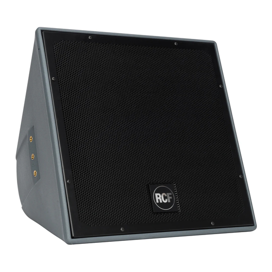
RCF S.P.A. THANKS YOU FOR PURCHASING THIS PRODUCT, WHICH HAS BEEN DESIGNED TO GUARANTEE RELIABILITY AND HIGH PERFORMANCES. DESCRIPTION P 8051-S is a bass-reflex subwoofer that belongs to the ‘P series’ for fixed indoor installation, but also outdoor (IP 55 protection) if installed as sealed box (its reflex ports need to be closed by using the respective plugs). It is equipped with a 15” hi-power neodymium woofer (4” voice coil). The cabinet is a single piece rotational moulded in medium density polyethylene (fully UV protected) and equipped with 12 x M 10 brass inserts, a stainless steel U-bracket and a pair of spacers for 90° mounting. The front logo is in aluminium and rotatable. The grille is in aluminium with open-cell fibres and water repellent woven fabric backing. INSTALLATION NOTES Loudspeakers are to be install by qualified personnel, respecting all safety standards. Loudspeakers are to be installed securely. Make sure the support structure (walls / ceilings) has the necessary mechanical characteristics for the loudspeaker weight, without the risk of a fall that could damage things or cause an injury. Use attachments elements suitable for walls / ceilings (e.g. screw anchors for bricks, screw anchors for concrete, etc.). After connecting a loudspeaker, insulate its unused wires! SEALED OR BASS-REFLEX... -
Page 7: Single Loudspeaker Installation
SINGLE LOUDSPEAKER INSTALLATION a) Horizontal U bracket installation: fix the loudspeaker to the U bracket by tightening the 2 bolts (M10) into the 2 loudspeaker central holes. Before tightening the 2 bolts, adjust the loudspeaker tilt and then (when you are sure of the proper angle) fix that position through thread-forming screws into the U bracket little holes next to the central hole for bolts. tilt the loudspeaker upwards b) Vertical U bracket installation: put the 2 shims on the loudspeaker and fix them by tightening 2 pairs of bolts (M10), then fix the loudspeaker to the U bracket by tightening other 2 bolts into the 2 loudspeaker central holes. Before tightening the last 2 bolts, adjust the loudspeaker horizontal aiming angle and then (when you are sure of the proper angle) fix that position through thread-forming screws into the U bracket little holes next to the central hole for bolts. -
Page 8: Array / Cluster Installation
ARRAY / CLUSTER INSTALLATION The optional RCF AC P15 A-BR kit includes the necessary accessories for a cluster made of 2 loudspeakers: i.e. P6215 with P8015-S subwoofer or P3115-T with P8015-S subwoofer. Two AC P15 A-BR kits are necessary for a cluster having 3 or (maximum) 4 loudspeakers. arning make clusTers WiTh more Than loudspeakers each SETTING OF THE ANGLE BETWEEN 2 LOUDSPEAKERS The angle between the 2 cluster loudspeakers depends on how the U brackets are matched. SETTING OF THE ANGLE The possible values are: 0° (no angle, the 2 loudspeakers are aimed to the same direction), BETWEEN 2 LOUDSPEAKERS 10°, 20°, 30°, 40°. A dedicated acoustic project / study is to be carried out to find the proper angle. black dots are the holes where to fix the... - Page 9 2 LOUDSPEAKER CLUSTER 2 LOUDSPEAKER CLUSTER The kit includes: 4 rods (A) 4 U brackets (B) nuts and washers (C) washers (C’) 2 plates / spacers (D) 2 washers / spacers (E) shims are provided with the loudspeakers aNd each shall be fixed through bolts (m10, with washers NoN iNcluded Put together and fix the 2 loudspeakers to the U brackets on both sides. The 2 spacers per side (the plate ‘D’ and the washer ‘E’) are needed for the second loudspeaker only.
- Page 10 Use 4 M10 D-shackles (not included, 2 on the top and 2 on the bottom; put on the rear corner holes of the U brackets) for the suspended installation with chains (non included).
- Page 11 EXAMPLES OF 3 OR 4 EXAMPLES OF 3 OR 4 LOUDSPEAKER CLUSTERS LOUDSPEAKER CLUSTERS 2 identical kits are necessary for a cluster having 3 or 4 loudspeakers. 3 LOUDSPEAKER CLUSTER 6 rods (A) 6 U brackets (B) nuts and washers (C) washers (C’) 2 plates / spacers (D) for the second loudspeaker only.
- Page 12 EXAMPLES OF 3 OR 4 4 LOUDSPEAKER CLUSTER LOUDSPEAKER CLUSTERS 8 rods (A) 8 U brackets (B) nuts and washers (C) washers (C’) 4 plates / spacers (D) for the second and the fourth loudspeaker only. 2 washers / spacers (E) for the fourth loudspeaker only.
-
Page 13: Connections
CONNECTIONS Warning: loudspeaker connections should be only made by qualified and personnel having the technical know-how or sufficient specific instructions (to ensure that connections are made correctly) in order to prevent any electrical danger. To prevent any risk of electric shock, do not connect loudspeakers when the amplifier is switched on. Before turning the system on, check all connections and make sure there are no accidental short circuits. The entire sound system shall be designed and installed in compliance with the current local laws and regulations regarding electrical systems. If the P 8015-S subwoofer is installed outdoor (and IP 55 protection grade is required), all electrical connections shall be put into weatherproof boxes / wall niches. P 8015-S subwoofer impedance is 8 Ω. BLUE Connect the loudspeaker BLUE wire to the amplifier output ‘+’. Connect the loudspeaker BROWN wire to the amplifier output ‘–’. BROWN P 8015-S subwoofers are dedicated for very low frequencies only, so these are to be used with ‘satellite’ loudspeakers. Separate amplification and an external crossover are needed. EXAMPLES OF BI-AMPLIFIED SYSTEMS P8015-S subwoofer can be matched to either P6215 or P3115-T (note: these are the optimal solutions in order to make common clusters, but it is also possible to use other separate ‘satellite’ loudspeakers). The audio signal is split by an external crossover; suggested cutoff frequency is 120 Hz. All frequencies below 120 Hz are sent to amplifiers for P 8015-S subwoofers, all frequencies above 120 Hz are sent to amplifiers for ‘satellite’ loudspeakers (i.e. either P 6215 or P 3115-T). - Page 14 NOTES ABOUT LOW NOTES ABOUT LOW IMPEDANCE CONNECTIONS IMPEDANCE CONNECTIONS The total loudspeaker impedance must not be lower than the amplifier output impedance. Note: a loudspeaker total impedance equal to the amplifier output one permits to get the maximum deliverable power (but an higher loudspeaker impedance entails less power). The total loudspeaker power shall be adequate for the maximum deliverable power of the amplifier. The loudspeaker line shall be short (for long distances, it may be necessary to use cables with large cross-section wires). TOTAL IMPEDANCE: 4 Ω TOTAL IMPEDANCE: 8 Ω 8 Ω 8 Ω 8 Ω Always use cables having wires with an adequate cross-section, considering the cable length and the total loudspeaker power. Loudspeaker lines must be kept separated from mains cables, microphone cables or others, in order to avoid inductive phenomena may cause hum or noises. Use loudspeaker cables with twisted wires to reduce hum caused by inductive effects due to coupling with electromagnetic fields. Do NOT connect the low impedance input directly to 100 V constant voltage lines.
-
Page 15: Specifications
SPECIFICATIONS Impedance 8 Ω Max. input power (RMS) 800 W Max. input power (peak) 3200 W Recommended amplifier power 1600 W Sensitivity (1 W, 1 m) 97 dB Max. sound pressure level (1 m) 132 dB (P: 3200 W) Frequency response (– 10 dB) 50 Hz ÷ 200 Hz Suggested frequency for external crossover 120 Hz Dimensions (w, h, d) 463 mm, 463 mm, 433 mm... -
Page 16: Avvertenze Per La Sicurezza
7. Nel caso che dal diffusore provengano odori anomali o fumo, spegnere immediatamente l’amplificatore relativo alla linea e poi scollegare il diffusore. 8. Non collegare a questo diffusore apparecchi ed accessori non previsti. Quando è prevista l’installazione sospesa, utilizzare solamente gli appositi punti di ancoraggio e non cercare di appendere il diffusore con elementi non idonei o previsti allo scopo. Verificare inoltre l’idoneità del supporto (parete, soffitto, struttura ecc.) e dei componenti utilizzati per il fissaggio (tasselli, viti, staffe non fornite da RCF ecc.) che devono garantire la sicurezza dell’impianto / installazione nel tempo, anche considerando, ad esempio, vibrazioni meccaniche normalmente generate da un trasduttore. 9. La RCF S.p.A. raccomanda vivamente che l’installazione di questo prodotto sia eseguita solamente da installatori professionali qualificati (oppure da ditte specializzate) in grado di farla correttamente e certificarla in accordo con le normative vigenti. Tutto il sistema audio dovrà essere in conformità con le norme e le leggi vigenti in materia di impianti elettrici. 10. Vi sono numerosi fattori meccanici ed elettrici da considerare quando si installa un sistema audio professionale (oltre a quelli prettamente acustici, come la pressione sonora, gli angoli di copertura, la risposta in frequenza, ecc.). - Page 17 11. Perdita dell’udito L’esposizione ad elevati livelli sonori può provocare la perdita permanente dell’udito. Il livello di pressione acustica pericolosa per l’udito varia sensibilmente da persona a persona e dipende dalla durata dell’esposizione. Per evitare un’esposizione potenzialmente pericolosa ad elevati livelli di pressione acustica, è necessario che chiunque sia sottoposto a tali livelli utilizzi delle adeguate protezioni; quando si fa funzionare un trasduttore in grado di produrre elevati livelli sonori è necessario indossare dei tappi per orecchie o delle cuffie protettive.
-
Page 18: Descrizione
RCF S.P.A. VI RINGRAZIA PER L’ACQUISTO DI QUESTO PRODOTTO, REALIZZATO IN MODO DA GARANTIRNE L’AFFIDABILITÀ E PRESTAZIONI ELEVATE. DESCRIZIONE P 8051-S è un subwoofer (diffusore per frequenze molto basse) di tipo “bass-reflex” che appartiene alla “serie P” per installazioni fisse al chiuso, ma anche all’aperto (con protezione IP 55) se predisposto come cassa chiusa (le sue “porte reflex” devono essere chiuse con tappi appositi). E’ provvisto di un woofer da 15 pollici ad alta potenza (con bobina da 4 pollici). Il corpo è costruito in resina plastica resistente ai raggi UV e la sua forma ne permette sia l’installazione singola sia la realizzazione di “cluster” (gruppo di diffusori allineati) tramite accessori opzionali (AC P15 A-BR). La griglia di protezione è in alluminio perforato con un rivestimento interno in tessuto impermeabile di poliuretano espanso a celle aperte. Il corpo è equipaggiato con 12 inserti M10 ed una staffa a “U”; il logo frontale è in alluminio ed è girabile. NOTE PER L’INSTALLAZIONE L’installazione dei diffusori deve essere effettuata da personale qualificato rispettando gli standard di sicurezza. Eseguire un’installazione sicura di ogni diffusore, controllando che la struttura di supporto (es. parete, soffitto, ecc.) abbia le necessarie caratteristiche meccaniche, tali da consentirle di sopportarne il peso senza il pericolo di cadute che potrebbero compromettere l’incolumità di persone e/o danneggiare cose. Utilizzare elementi di fissaggio adatti al tipo di struttura che deve sostenere i diffusori (es. tasselli per mattoni forati, tasselli per calcestruzzo, ecc.). -
Page 19: Installazione Di Un Singolo Diffusore
INSTALLAZIONE DI UN SINGOLO DIFFUSORE a) Installazione con staffa in posizione orizzontale: fissare il diffusore alla staffa a U avvitando i due bulloni (M10) nei due fori centrali (del diffusore). Prima di stringere i due bulloni, regolare l’inclinazione verticale del diffusore e successivamente (quando si è certi dell’angolo) fissarla tramite viti autofilettanti poste nei fori della staffa a U adiacenti a quelli per i bulloni. ’ NoN iNcliNare il diffusore verso l alto b) Installazione con staffa in posizione verticale: inserire i due spessori e bloccarli tramite due coppie di bulloni (M10), poi fissare il diffusore alla staffa a U avvitando altri due bulloni nei due fori centrali (del diffusore). Prima di stringere i due bulloni centrali, regolare l’angolazione orizzontale del diffusore e successivamente (quando si è certi dell’angolo) fissarla tramite viti autofilettanti poste nei fori della staffa a U adiacenti a quelli per i bulloni. -
Page 20: Installazione A "Cluster
INSTALLAZIONE A “CLUSTER” Il kit opzionale RCF AC P15 A-BR include gli accessori necessari per la formazione di un “cluster” composto da 2 diffusori: modelli P6215 / P8015-S (subwoofer) oppure P3115- T / P8015-S. Due kit AC P15 A-BR sono necessari per formare “cluster” con 3 o al massimo 4 diffusori. : non “ ” TTenzione assemblare clusTer con più di diffusori ciascuno IMPOSTAZIONE DELL’ANGOLO TRA 2 DIFFUSORI IMPOSTAZIONE DELL’ANGOLO L’impostazione dell’angolo tra 2 diffusori di un cluster si effettua tramite la posizione in TRA 2 DIFFUSORI cui sono installate le staffe. I valori possibili sono: 0° (nessuna angolazione, i 2 diffusori sono puntati nella stessa direzione), 10°, 20°, 30°, 40°. La scelta dell’angolo più opportuno necessita di uno studio acustico dedicato. i puNti Neri rappreseNtaNo i fori di fissaggio per i perNi... - Page 21 CLUSTER COMPOSTO CLUSTER COMPOSTO DA 2 DIFFUSORI DA 2 DIFFUSORI Il kit include: 4 perni (A) 4 staffe (B) dadi e rondelle (C) rondelle (C’) 2 piastre / distanziatori (D) 2 rondelle / distanziatori (E) spessori soNo iNclusi coN i relativi diffusori e ciascuNo deve essere fissato tramite (m10, bulloNi coN roNdelle NoN iNclusi Unire e fissare i 2 diffusori alle staffe su entrambi i lati. I due distanziatori per lato (piastra “D” e rondella “E”) servono solo sul secondo diffusore (con le staffe più esterne).
- Page 22 Utilizzare 4 grilli (non inclusi) M10 (agli angoli posteriori delle staffe; 2 in alto e 2 in basso) per l’installazione sospesa del cluster con catene (non incluse).
- Page 23 ESEMPI DI CLUSTER ESEMPI DI CLUSTER CON 3 O 4 DIFFUSORI CON 3 O 4 DIFFUSORI Per la realizzazione di cluster con 3 o 4 diffusori, occorrono 2 kit identici. CLUSTER CON 3 DIFFUSORI 6 perni (A) 6 staffe (B) dadi e rondelle (C) rondelle (C’) 2 piastre / distanziatori (D) solo per il secondo diffusore.
- Page 24 ESEMPI DI CLUSTER CLUSTER CON 4 DIFFUSORI CON 3 O 4 DIFFUSORI 8 perni (A) 8 staffe (B) dadi e rondelle (C) rondelle (C’) 4 piastre / distanziatori (D) solo per il secondo ed il quarto diffusore 2 rondelle / distanziatori (E) solo per il quarto diffusore.
-
Page 25: Connessioni
CONNESSIONI Attenzione: per il collegamento del diffusore si raccomanda di rivolgersi a qualificato ed addestrato, ossia personale avente conoscenze tecniche o esperienza o istruzioni specifiche sufficienti per permettergli di realizzare correttamente le connessioni e prevenire i pericoli dell’elettricità. Per evitare il rischio di shock elettrici, non collegare il diffusore con l’amplificatore acceso. Prima di far funzionare il diffusore, è buona norma ricontrollare tutte le connessioni, verificando attentamente che non vi siano dei cortocircuiti accidentali. Tutto l’impianto di sonorizzazione dovrà essere realizzato in conformità con le norme e le leggi vigenti in materia di impianti elettrici. Se il subwoofer P8015-S è installato all’aperto (dove si richiede la protezione IP 55), le connessioni elettriche devono essere poste all’interno di una scatola di protezione a tenuta stagna (oppure una nicchia incassata a parete). L’impedenza del subwoofer P 8015-S è 8 Ω. Collegare il conduttore BLU del diffusore al morsetto dell’amplificatore “+”; collegare il MARRONE conduttore MARRONE del diffusore al morsetto dell’amplificatore “–”. I subwoofer P 8015-S sono dedicati alla diffusione delle sole frequenze molto basse, pertanto devono essere abbinati a diffusori “satelliti”, necessitano di amplificazione separata e di un “crossover” esterno (apparecchio che separa in uscita diverse bande di frequenze). ESEMPI DI SISTEMI BI-AMPLIFICATI I subwoofer P8015-S possono essere abbinati ai diffusori RCF P6215 oppure P3115- T (nota: queste sono le soluzioni ottimali per formare “cluster” comuni, ma è anche possibile utilizzare altri tipi di diffusori come “satelliti” separati). Il segnale audio è diviso da un “crossover” esterno; si consiglia una frequenza di taglio di 120 Hz. Tutte le frequenze sotto 120 Hz sono inviate agli amplificatori per i subwoofer P 8015-S; tutte le frequenze sopra 120 Hz sono inviate agli amplificatori per i diffusori “satelliti” (ad esempio, P 6215 oppure P 3115-T). - Page 26 NOTE SUI SISTEMI CON NOTE SUI SISTEMI CON CONNESSIONE A BASSA IMPEDENZA CONNESSIONE A BASSA IMPEDENZA L’impedenza totale dei diffusori non deve essere inferiore a quella d’uscita dell’amplificatore; nota: l’impedenza complessiva dei diffusori uguale a quella d’uscita dell’amplificatore permette l’erogazione della massima potenza (mentre un’impedenza superiore comporta una riduzione della potenza erogata). La somma delle potenze dei diffusori deve essere adeguata alla potenza massima erogabile dall’amplificatore.
-
Page 27: Dati Tecnici
DATI TECNICI Impedenza 8 Ω Potenza RMS 800 W Potenza massima (picco) 3200 W Potenza raccomandata dell’amplificatore 1600 W Sensibilità (1 W, 1 m) 97 dB Max. pressione sonora (1 m) 132 dB (P: 3200 W) Risposta in frequenza (– 10 dB) 50 Hz ÷ 200 Hz Frequenza suggerita per il crossover esterno 120 Hz Dimensioni (l, h, p) 463 mm, 463 mm, 433 mm... - Page 28 RCF SpA: Via Raffaello, 13 - 42124 Reggio Emilia > Italy tel. +39 0522 274411 - fax +39 0522 274484 - e-mail: rcfservice@rcf.it...
Need help?
Do you have a question about the P 8015-S and is the answer not in the manual?
Questions and answers