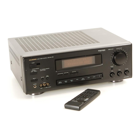
Summary of Contents for Onkyo A-SV610PRO
- Page 41 NPN Transistor with Positive supply and +ve bias. [[Rectangular box shows DVM]] This typical circuit often seen in amplifier and power supply is a common approach to general application circuit design. This circuit is a normal configuration often used in amplifiers having an inverted output. The output of Q1 at its emitter shall have a loss up to 650mv depending on the transistor gain.
- Page 42 PNP transistor used with Positive Power supply to Emitter and +ve biased. [[Rectangular box shows DVM]] n this kind of configuration the transistor is biased by Positive voltage. Do to the characteristic of the PNP transistor reaction to a Positive supply at the emitter, the collector voltage will retain above the 600mv minimum switching voltage.
- Page 43 O N K Y O U S A C O R P O R A T I O N INFO/RESET_ALL 02/27/01 Technical Tip: The procedure given above will clear all consumer saved setup. It is therefore important to document customer settings before performing reset.
- Page 44 Date: 07/09/02 Ref: GEN_10 Model: All Application: General Knowledge What is a PCB ? Solution: PCB means "Printed Circuit Board" In early 1960, most (if not all) electronic assemblies were assembled in a 'point-to-point' fashion. All of the components were strung through the air, literally supported by their wire leads.
- Page 45 file:///C:/service.onkyousa.com/webtech_data/electricalcode.htm ELECTRICAL / MECHANICAL APPLICATION FORMULAS Power - AC Circuits, Power - DC Circuits, Mechanical, Fans & Blowers, Pump Motors OHMS LAW Volts (E) = Amps (I) x Ohms (R) Amps (I) = Volts (E) / Ohms (R) Ohms (R) = Volts (E) / Amps (I) R=Ohms, E=Volts, I=Amperes POWER - AC CIRCUITS Eff.
- Page 46 NPN Transistor working with Negative supply and Negative bias. Fig1 Fig2 [[Rectangular box shows DVM]] NPN transistor response to a negative supply and negative bias is not different than PNP with Positive bias and Positive supply. Inherently NPN transistor will fully turn off with negative supply at its collector and biased with any voltage ≤580mv positive.
- Page 47 Techniques for Replacing Surface Mount (SMD) IC’s Every technician has had to replace a surface mount device (SMD) IC at one time or another. How do you successfully remove and replace a surface mount IC? By successful I mean removing the defective IC without damaging the delicate traces on the PC board and aligning and soldering the replacement IC in place.
- Page 48 board’s copper traces. One word of caution, this technique takes some practice. You are using a sharp razor knife that WILL cut the boards traces if you use too much force while cutting through the IC’s pins. Check the board before you solder the new IC in place. It is highly recommended that you practice this method on some scrap boards before trying it on a customers unit.
- Page 49 IC Replacement Soldering Techniques: OK, now that you removed the IC from the board, how do you solder the replacement IC on the board? Here are some basic techniques for soldering a replacement IC to the PC board. First, make sure the lands are CLEAN. That means removing all solder and flux left behind during the IC extraction process.
- Page 50 PNP Transistor behavior with Negative supply and bias. [[Rectangular box shows DVM]] Positive as ground reference; Q1 is biased by the supply voltage -ve, variable depending on the value of R3. In such configuration Q1 can be turned off completely. The output of Q1 collector is equal to the vb less the 600mv loss within the transistor.


Need help?
Do you have a question about the A-SV610PRO and is the answer not in the manual?
Questions and answers