Advertisement
SV-LCD56B1 Quick Installation Guide
Safety Vision SV-LCD56B1
Color TFT LCD Collision Avoidance System
Quick Installation Guide
Overview
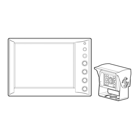
The Safety Vision SV-LCD56B1 Color TFT LCD Collision
Avoidance System is designed for rugged, mobile
environments and turns on automatically when the
vehicle transmission is in reverse gear. Each system
includes a 5.6-inch monitor, camera, and system power
cable with inline control box. The system monitor has an
integrated speaker, and the system camera has an
integrated microphone, permitting the driver to both see
and hear activity within the camera's range. One camera
can be connected to the SV-LCD56B1 system, and one
camera is provided with the system.
Components of the SV-LCD56B1 system include:
Safety Vision SV-LCD56B1 Monitor, which features:
A 5.6-inch TFT LCD screen
Wide field of view
Integrated speaker
Safety Vision SV-625B-KIT, which includes the
camera (Part Number SV-625B) and a 65-foot
extension cable (Part Number SV-523B) and has the
following features:
Copyright © 2007 Safety Vision, L.P.
Safety Vision and the Safety Vision logo are trademarks of Safety Vision, L.P.
Notice to Users: This document is confidential and contains proprietary information belonging to Safety Vision, L.P. This document and the information
contained herein cannot be distributed, communicated, reproduced, altered, or disseminated by any means, in whole or in part, without the express
written consent of Safety Vision, L.P. Possession of this document constitutes the user's acceptance of these nondisclosure covenants. The information
in this document is believed to be accurate in all respects. However, Safety Vision cannot assume responsibility for any consequences resulting from the
use thereof. The information contained herein is subject to change without notice. Revisions or new editions to this publication may be issued to
incorporate such changes.
Safety Vision ▪ 6100 West Sam Houston Parkway North ▪ Houston, Texas 77041 ▪ USA
SV-LCD56B1 QIG Ver.1.0.doc
Rugged, water-resistant housing
CCD image sensor for improved image quality
Wide field of view (135° diagonal, 108° horizontal)
LEDs that generate infrared light for improved
image quality in low-light situations
Integrated microphone
Safety Vision SV-ILCB system power cable with inline
control box , which provides DC power to the monitor
and camera and has 1 audio/video input and 1
audio/video output
Important Safety Precautions
Install and operate the SV-LCD56B1 system with the
following safety precautions in mind:
The ground (black) wire of the system power cable
must be connected directly to the vehicle chassis.
Use only the correct voltage (12 to 24 VDC).
To reduce the risk of electrical shock, disconnect the
battery from the electrical system of the vehicle before
starting the installation.
Do not expose the monitor to water or other liquids.
To avoid the risk of electric shock, do not disassemble
the system components, and keep cables away from
sharp objects.
Do not block the ventilation holes in the monitor
housing.
This system is designed to assist the vehicle driver
with rear vision only. Do not attempt to view the
monitor while driving forward.
Select inconspicuous cable routes that do not interfere
with normal driver or passenger mobility.
September 2007
1
Advertisement
Table of Contents

Related Manuals for Safety Vision SV-LCD56B1

Summary of Contents for Safety Vision SV-LCD56B1
- Page 1 Safety Vision, L.P. Possession of this document constitutes the user’s acceptance of these nondisclosure covenants. The information in this document is believed to be accurate in all respects. However, Safety Vision cannot assume responsibility for any consequences resulting from the use thereof.
-
Page 2: Supplied Hardware
SV-LCD56B1 Quick Installation Guide September 2007 C MENU BUTTON—when pressed and held for a few Supplied Hardware seconds, initiates display of onscreen user controls for image contrast and brightness and speaker The following hardware is supplied for installation with volume each SV-LCD56B1 system: D + BUTTON—UP button—increases the value for... -
Page 3: Optional Components
4. Connect the connector of the monitor cable to the monitor connector of the inline control box. Devices other than the components supplied with the SV-LCD56B1 system can be connected to the system. Typical Installation SV-LCD56B1 Monitor 1. Select a mounting surface for the monitor, which can be mounted overhead or elsewhere in the vehicle cabin (including on the floor or console). - Page 4 SV-LCD56B1 Quick Installation Guide September 2007 4. Connect the connector of the camera extension cable SV-625B Camera to the camera connector of the inline control box. 1. Select an appropriate mounting location for the SV-ILCB System Power Cable with Inline...
-
Page 5: Specifications
Operating Temperature 5°F to 149°F (-15°C to 65°C) Storage Temperature -13°F to 185°F (-25°C to 85°C) Safety Vision, L.P. (“SV”) makes the following limited warranty, Weight 0.75 pounds (0.34 kg) which is effective at the time of the original end-user purchase. -
Page 6: How To Reach Us
SV-LCD56B1 Quick Installation Guide September 2007 Customer’s Responsibility (RMA) number. The customer must include this number on the outside of each package shipped to SV. The above warranty is subject to the following conditions: Important Packing and Shipping Instructions Customer must notify SV within 10 days of discovering the...
Need help?
Do you have a question about the SV-LCD56B1 and is the answer not in the manual?
Questions and answers