Table of Contents
Advertisement
Ver. 8
Please refer to the
MODIFICATION NOTICE.
SERVICE MANUAL
MODEL
JP
E3
E2
EK
E2A E1C E1K EUT
PMA-710AE
INTEGRATED STEREO AMPLIFIER
●
For purposes of improvement, specifications and design are subject to change without notice.
●
Please use this service manual with referring to the operating instructions without fail.
●
Some illustrations using in this service manual are slightly different from the actual set.
e
D&M Holdings lnc.
S0279-0V08DM/DG1105
Copyright 2011 D&M Holdings Inc. All rights reserved.
WARNING: Violators will be prosecuted to the maximum extent possible.
Advertisement
Table of Contents

Related Manuals for Denon PMA-710AE


Summary of Contents for Denon PMA-710AE
-
Page 1: Service Manual
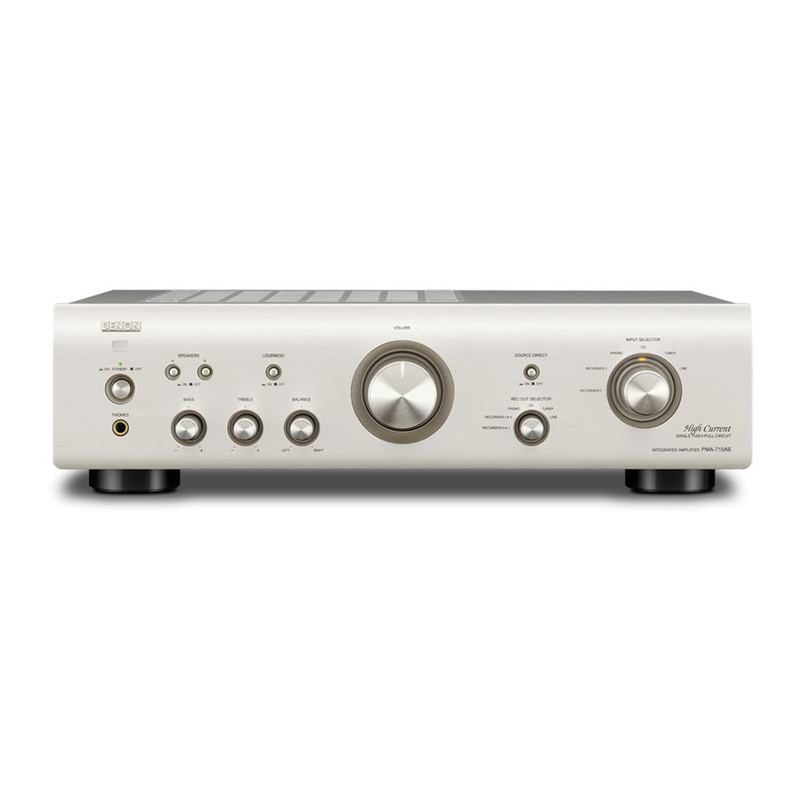
Please refer to the MODIFICATION NOTICE. SERVICE MANUAL MODEL E2A E1C E1K EUT PMA-710AE INTEGRATED STEREO AMPLIFIER ● For purposes of improvement, specifications and design are subject to change without notice. ● Please use this service manual with referring to the operating instructions without fail. -
Page 2: Safety Precautions
PMA-710AE... - Page 3 DIMENSION PMA-710AE...
-
Page 4: Wire Arrangement
If wire bundles are untied or moved to perform adjustment or parts replacement etc.,be sure to rearrange them neatly as they were originally bundled or placed afterward. Otherwise, incorrect arrangement can be a cause of noise generation. Wire arrangement viewed from the top Front Panel side Back Panel side PMA-710AE... - Page 5 • Refer to the table below for a description of the direction in which the photos were taken. • Photographs for which no direction is indicated were taken from above the product. The viewpoint of each photograph (Photografy direction) [View from above] Front side PMA-710AE...
-
Page 6: Front Panel Assy
Style pin : Loose (3) Disconnect the connector wires, then remove the screws. CN55 CN50 CN94 CN94 CN93 CN51 CN52 CN53 CN95 CN92 Please refer to "EXPLODED VIEW" for the disassembly method of each P.W.B included in FRONT PANEL ASSY. PMA-710AE... -
Page 7: Rear Panel
REAR PANEL MAIN PCB ASSY Please refer to "EXPLODED VIEW" for the disassembly method in MAIN PCB ASSY. 5. POWER TRANSFORMER Proceeding : TOP CABINET → POWER TRANSFORMER Please refer to "EXPLODED VIEW" for the disassembly method in POWER TRANSFORMAER. PMA-710AE... -
Page 8: Block And Level Diagram
BLOCK AND LEVEL DIAGRAM PMA-710AE... - Page 9 (4) Then after 2 minutes warm up adjust VR31 and VR32 so that the DC voltmeter reads 10 ±1mV. (5) And after 10 minutes warm up adjust VR31 and VR32 so that the DC voltmeter reads 10 ±0.5mV. DC Voltmeter CN31 VR31 Power Trans VR32 CN32 Volume PMA-710AE...
-
Page 10: Troubleshooting
Set operates, but then power indicator LED flashes red (protection mode is set). Offset voltage output is 1V or Damaged power amplifier cir- Check the power amplifier output's offset voltage. greater. cuit. No offset voltage is output. Check the bias current. PMA-710AE... - Page 11 3. The power turned on, but a sound does not output normally. (Single channel) Power indicator LED is lit normally (green or Check each connector. orange). Check the voltage of each department. Check the operation of the switching relay, switching IC and speaker relay. Check the Signal line. PMA-710AE...
- Page 12 STOP ACT. INT0 PROTECTOR PDO4/PWM4/PPG4 P. DIRECT RELAY DATA STROBE INT4 S. DIRECT RELAY P. DIRECT SW S. DIRECT SW INT3 AC RELAY 1 VOLUME UP VOLUME DOWN INT2 REMOTE IN INT1 POWER OFF PDO3/PWM3 AC RELAY 2 AIN0 MODEL PMA-710AE...
- Page 13 TAPE-2 TC9164AN (IC22) TC9164AN L-COM R-COM L-COM R-COM L-COM R-COM R-COM L-COM L-COM R-COM DATA R-COM L-COM DATA Shift Register TC9163AN (IC21) TC9163AN L-COM R-COM L-COM R-COM L-COM R-COM R-COM L-COM L-COM R-COM DATA R-COM L-COM DATA Shift Register PMA-710AE...
- Page 14 ---MEMO--- PMA-710AE...
- Page 15 PRINTED WIRING BOARDS MAIN PCB ASSY (1/2) COMPONENT SIDE PMA-710AE...
- Page 16 MAIN PCB ASSY (2/2) FOIL SIDE PMA-710AE...
- Page 17 FRONT PCB ASSY (1/2) COMPONENT SIDE PMA-710AE...
- Page 18 FRONT PCB ASSY (2/2) FOIL SIDE PMA-710AE...
-
Page 19: Note For Parts List
Indicates number of zeros after efective number. (0 or 1) (More than 2) 2-digit effective number. 2-digit effective number. ・ Units:pF ・ Units:pF ・ When the dielectric strength is indicated in AC,"AC" is included after the dieelectric strength value. PMA-710AE... -
Page 20: Parts List Of Pcb Unit
00MGG05010160 CARBON FILM RES 1ohm 1/4W J R923 00D9430194308 RES. FUSE 0.3ohm 1/6W K CRQ16AKR30T R924,925 METAL OXIDE RES 68 ohm 1W J KRG1SANJ680RT R929 00MGG05022140 CARBON FILM RES 2.2ohm 1/4W J VR31,32 00D9430196908 SEMI FIXED RESISTOR 500 ohm CVN1GE501B01T PMA-710AE... - Page 21 CEMICONDUCTOR CAP 0.1uF 50VZF CCFT1H104ZF C951,952 CERAMIC CAP 0.0047uF 2.5KV KCKDKS472ME OTHERS PARTS GROUP BK91 PCB BRACKET (A) CMD1A188 BN91 WIRE ASSY(2P, 300MM, 7.9MM) CWB4DA32300UZ CN31,32 WAFER 3PIN 2MM CJP03GA01ZY CN51 STRAIGHT WAFER 7PIN 2MM CJP07GI236ZW CN52 STRAIGHT WAFER 7PIN 2.5MM CJP07GI237ZW PMA-710AE...
- Page 22 POWER RERAY G2R-14 CSL2C002ZE RY92 00D9430194900 POWER RERAY G5PA-1 CSL1E002ZE TH09 00D9430194609 POSISTOR PTFM04BB222QN34 CRTPTFM04BB222Q TH51 00D9430194502 THERMISTOR ASSY(170MM) CRT0217025MM z T901 00D9430193203 SUB TRANSFORMER CLT5I008ZE z T901 943101005870S SUB TRANSFORMER CLT5I008ZH HFUSE HOLDER KJCFC5S HEAT SINK CMY2A048 SCREW 3X8 CTB3+8JR PMA-710AE...
-
Page 23: Front Pcb Unit Ass'y
CSRCA001Z CAPACITORS GROUP C401 ELECT CAP 100uF 16V CCEA1CH101T C402 CHIP CAP 0.01uF 50V CCUS1H103KC C403 ELECT CAP 100uF 16V CCEA1CH101T C404 CHIP CAP 0.01uF 50V CCUS1H103KC C405 ELECT CAP 3300uF 16V CCEA1CH332E C406 ELECT CAP 22uF 50V CCEA1HH220T PMA-710AE... - Page 24 LOCKING TYPE, STRAIGHT WAFER 2MM CJP03GI236ZW CN94 WAFER CJP02GA89ZM JK41 00D9430198003 PHONE JACK HJJ2E018Z RC51 00D9430194706 REMOTE SENSOR(KSM603TH2E) CRVKSM603TH2E SW51 00D9430194803 PUSH SW(JPS-4281SA) CSH2D013Z SW52-54 00D9430199400 PUSH SW(220014) KSH2B003Z z SW91 00D9430140609 PUSH SW(CSH1A010ZV) CSH1A010ZV X401 00D9430196403 CERAMIC RESONATOR, CSTLS4M19G56-A0 CVFCSTLS4M19G56-A0 PMA-710AE...
- Page 25 ---MEMO--- PMA-710AE...
- Page 26 EXPLODED VIEW 19-1 19-2 WARNING: Parts marked with this symbol have critical characteristics. Use ONLY replacement parts recommended by the manufacturer. PMA-710AE...
-
Page 27: Parts List Of Exploded View
INNER PANEL CGW3A425B28 943443005960D INNER PANEL CGW3A425RGG45 00D9430190206 REMOCON WINDOW CGU1A396A8 00D9430190109 REMOCON WINDOW CGU1A396 00D9430189903 LENS CGL1A254 00D1310158049 DENON BADGE CGB1A140U 00D1310158052 DENON BADGE CGB1A140T 00D9430179502 POWER KNOB CGK1A124ZA 00D9430179609 POWER KNOB CGK1A124YA 00D9430201505 PUSH KNOB CBC2A155B28 00D9430201602 PUSH KNOB... - Page 28 CTB3+8GFN NUT(M9) WASHER SCREW 3X8 CTW3+8JR SCREW 3X8 CTB3+8JR SCREW 3X6 CTB3+6FFZR SCREW 3X12 CTW3+12JR 00D9430191001 SPECIAL SCREW CHD1A012R DOT SCREW 3X8 CTBD3+8JFZR DOT SCREW 3X10 CTBD3+10GFZR SCREW 3X18 CTW3+18JR SCREW 4X8 CTB4+8FR SCREW 4X6 CTWD4+6FFZR SCREW 4X6 CTWD4+6FFN PMA-710AE...
-
Page 29: Packing View
S.S.LIST(EX) CQE1A226R 943307004880D REMOCON CARTPMA510AEBK 943307004890D REMOCON CARTPMA510AESP BATTERY (SIZE 'AAA') CABR03PPB POLY BAG CPB1061W POS LABEL BKE2 CQB1A773T POS LABEL SPE2 CQB1A773U POS LABEL CQB1A773Q CONTROL LABEL CQB1A627 00D9430194804 COLOR LABEL CQB1A676 CARTON LABEL(C) CQB1A940Y DATE LABEL CQB1A622 PMA-710AE... -
Page 30: Wiring Diagram
WIRING DIAGRAM PMA-710AE... - Page 31 --MEMO-- PMA-710AE...
-
Page 32: Note For Schematic Diagram
NOTICE: ALL RESISTANCE VALUES IN OHM. k=1,000 OHM M=1,000,000 OHM ALL CAPACITANCE VALUES IN MICRO FARAD. P=MICRO-MICRO FARAD EACH VOLTAGE AND CURRENT ARE MEASURED AT NO SIGNAL INPUT CONDITION. CIRCUIT AND PARTS ARE SUBJECT TO CHANGE WITHOUT PRIOR NOTICE. PMA-710AE... - Page 33 SIGNAL LINE SCHEMATIC DIAGRAMS (1/2) CUP12196-1 MAIN Part CUP12196-2 Power Part PMA-710AE...
- Page 34 SIGNAL LINE SCHEMATIC DIAGRAMS (2/2) CUP12195-1 Tone Part CUP12195-2 MCU Part CUP12195-3 Function SW Part CUP12195-4 Volume Part CUP12195-5 Power SW, H/P Part PMA-710AE...
Need help?
Do you have a question about the PMA-710AE and is the answer not in the manual?
Questions and answers