Table of Contents
Advertisement
Advertisement
Table of Contents

Related Manuals for sorin 3T

Summary of Contents for sorin 3T
-
Page 1: Operating Instructions
Heater-Cooler System 3T Operating Instructions... - Page 2 Registered Trademark of the Pall Corporation Indications for use The Stöckert Heater-Cooler System 3T is used with a Stöckert S3 heart-lung machine and/or any other heart-lung-machine featuring a separate temperature control for extracorporeal perfusion of durations of up to 6 hours.
-
Page 3: Table Of Contents
Heater-Cooler System 3T • Table of Contents Table of Contents Introduction About these operating instructions ............1.1 1.1.1... - Page 4 Heater-Cooler System 3T • Table of Contents 4 Installation Preparing the installation ..............4.1 4.1.1...
- Page 5 Heater-Cooler System 3T • Table of Contents 6 Routine maintenance General instructions for maintenance ............6.2 6.1.1...
- Page 6 Heater-Cooler System 3T • Table of Contents Notes: CP_IFU_16-XX-XX_USA_015...
-
Page 7: Introduction
Heater-Cooler System 3T • Introduction Introduction About these operating instructions These operating instructions are solely intended for qualified perfusionists as the basis for using, operating, and maintaining the heater-cooler. Therefore, in the interest of the safety of both, the patient and the operator: Read these operating instructions thoroughly before using the heater-cooler for the first time! These operating instructions provide valuable information even for the experienced user. -
Page 8: The Chapters In These Operating Instructions
Heater-Cooler System 3T • Introduction 1.1.2 The chapters in these operating instructions In chapter... you will find the following information: ➜ Introduction Symbols used in these operating instructions ➜ Overview on chapters (this table) ➜ 2 Safety Important safety instructions for the... -
Page 9: Safety
This device complies with the requirements of EU Directive 93/42/EEC of the European Council for Medical Devices. The Heater-Cooler System 3T is a class IIb medical device (MDD 93/42/EEC). A Declaration of Conformity has been issued for the heater-cooler. CP_IFU_16-XX-XX_USA_015... -
Page 10: Regulations And Safety Instructions
Any use beyond this specification is not in accordance with the regulations and SORIN GROUP DEUTSCHLAND GMBH will not assume any liability for damage in such a case. Usage in accordance with regulations also includes compliance with the operating instructions, as well as repair and maintenance according to the maintenance instructions. -
Page 11: General Safety Instructions
◗ Do not perform any modifications or extensions to the heater-cooler unless they have been tested and approved by SORIN GROUP DEUTSCHLAND GMBH, or else SORIN GROUP DEUTSCHLAND GMBH cannot assume any liability or responsibility. ◗ Keep the heater-cooler clean! Doing so will prevent possible contact errors and faults due to dirt. -
Page 12: Operational Safety
Heater-Cooler System 3T • Safety 2.2.4 Operational safety ◗ Prior to working with the heater-cooler, the user must have thoroughly read the operating instructions and have become familiar with the device functions! ◗ Ensure that the heater-cooler is placed on a horizontal surface and the castor brakes have been locked prior to operation. -
Page 13: Electrical Safety
◗ Accessories and supplementary devices which have not been tested and approved by SORIN GROUP DEUTSCHLAND GMBH must prove that their use does not pose a safety hazard (see chap. 7.4 “Accessories” on page 7.6). 2.2.5 Electrical safety ◗... -
Page 14: Safety Instructions For Routine Maintenance
◗ Repair work on the heater-cooler must only be carried out by authorized service personnel. Only original spare parts from SORIN GROUP DEUTSCHLAND GMBH must be used in order to guarantee the proper functioning of the system. ◗... -
Page 15: Safety Features Of The Heater-Cooler
Heater-Cooler System 3T • Safety 2.3 Safety features of the heater-cooler ◗ The heater-cooler runs a self-test during power-up. Check whether all LEDs, the 7-segment displays and the beep alarm function correctly. ◗ Visual and audible alarms indicate when an internal error has occurred. - Page 16 Heater-Cooler System 3T • Safety CP_IFU_16-XX-XX_USA_015...
-
Page 17: System Description
3.1.1 Components The common delivery scope contains the standard components stated below. For further components (“optional components”), please contact SORIN GROUP DEUTSCHLAND GMBH, or your local SORIN GROUP DEUTSCHLAND GMBH distributor. Standard components ◗... -
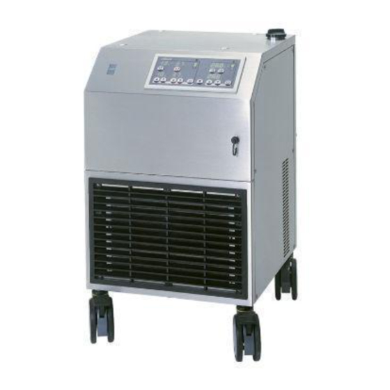
Page 18: Structure Of The Heater-Cooler
Heater-Cooler System 3T • System description 3.2 Structure of the heater-cooler 3.2.1 Complete overview Fig. 1: Overview CP_IFU_16-XX-XX_USA_015... - Page 19 Heater-Cooler System 3T • System description Item Designation Function ➜ 1 Mains power switch Powering the heater-cooler up/down ➜ Integrated automatic cutout ➜ 2 Control panel For separated operation and configuration of the two functional groups (3 water circuits) – patient circuits and –...
-
Page 20: Overview - Control Panel
Heater-Cooler System 3T • System description 3.2.2 Overview - control panel The control panel manages all control and monitoring functions of the heater-cooler. These are: ◗ Adjusting the set values, ◗ Starting and stopping the pumps, ◗ The display of all set and actual temperatures, ◗... -
Page 21: Overview - Control Panel S5/C5 System
Heater-Cooler System 3T • System description 3.2.3 Overview - control panel S5/C5 System If the heater-cooler is operated with the S5/C5 System, no further connections or steps are necessary. The settings of the heater-cooler may either be performed via the menu of the S5/C5 System or directly on the base unit of the heater-cooler. - Page 22 Heater-Cooler System 3T • System description Notes: CP_IFU_16-XX-XX_USA_015...
-
Page 23: Installation
Heater-Cooler System 3T • Installation Installation Preparing the installation Apart from the components included in the delivery, you still need the following components for installing your heater-cooler: ◗ Compatible tubing sets for connecting the heating/cooling blanket and the oxygenator. ◗... -
Page 24: Performing The Installation
Heater-Cooler System 3T • Installation 4.2 Performing the installation 4.2.1 Placing the heater-cooler Fig. 3: Placing the heater-cooler ◗ Place the heater-cooler on even floors only. ◗ Lock the brakes (at the front castors 19), after having placed the heater-cooler. -
Page 25: Water Connections
Heater-Cooler System 3T • Installation 4.2.2 Water connections Connecting tubings to the water circuits Note: Pay attention to hand hygiene and protective barriers by disinfecting your hands and using disposable gloves. Requirements for connection: ◗ Disinfect the connectors and fittings on the tubings before connecting them to the heater-cooler (see chap. - Page 26 Heater-Cooler System 3T • Installation Fig. 5: Connecting the tubings ◗ Push the ring of the fast (Hansen-type) connector in the direction of the arrow to insert or remove the tubings. ◗ Insert the tubings with connector and allow the locking ring to return to its original position.
-
Page 27: Connecting The Overflow Tube
Heater-Cooler System 3T • Installation Connecting the overflow tube Fig. 6: Connecting the overflow tube ◗ Hang the overflow bottle 14 with its holder on the ventilation grill at the rear of the heater-cooler. ◗ Connect a 1/2" tubing to the overflow outlet 13. - Page 28 Heater-Cooler System 3T Fig. 7: Overview connecting additional devices All components used in conjunction with the Heater-Cooler System 3T (please see the above overview) have been tested and determined safe and effective to the extent possible. Please also see chap. 7.4 on page 7.6 for information about safe usage of the disposables.
-
Page 29: Opening/Closing The Venting Valves
Heater-Cooler System 3T • Installation Opening/closing the venting valves Fig. 8: Opening/closing the venting valves For operating the heater-cooler, the venting valves have to be opened (position A). For emptying the tubing system, the venting valves have to be closed (position B). -
Page 30: Electrical Connections
Heater-Cooler System 3T • Installation 4.2.3 Electrical connections Power supply Fig. 10: Connection to the power supply The heater-cooler requires an AC line rated at 16 A. Ideally, the heater-cooler should be connected to a separate dedicated AC-line. ◗ Connect the equipotential equalization cable to the potential equalization point 17 of the heater-cooler. -
Page 31: Operation With The S5/C5 System
Heater-Cooler System 3T • Installation 4.2.4 Operation with the S5/C5 System No additional remote control modules are required for operation of the heater-cooler with the S5/C5 System. No further connections or steps are necessary. CP_IFU_16-XX-XX_USA_015... - Page 32 Heater-Cooler System 3T • Installation Notes: 4.10 CP_IFU_16-XX-XX_USA_015...
-
Page 33: Operation
Heater-Cooler System 3T • Operation Operation Please read the following chapter thoroughly before operating the heater-cooler for the first time. General information The heater-cooler can be operated individually. CP_IFU_16-XX-XX_USA_015... -
Page 34: Filling The Water Tanks
Heater-Cooler System 3T • Operation 5.2 Filling the water tanks The three tanks for the patient circuits and the cardioplegia circuit (warm/cold) are filled via the common filler neck 3. Note: Pay attention to hand hygiene and protective barriers by disinfecting your hands and using disposable gloves. - Page 35 Heater-Cooler System 3T • Operation Filling the water tanks ◗ Switch on the heater-cooler (by pressing the mains power switch 1) in order to use the water level displays. ◗ Press the key Audio alarm off 29. ◗ Remove the cover of the filler neck 3 by turning it 90°...
- Page 36 Heater-Cooler System 3T • Operation ◗ Pour 150 ml (5 US fl. oz.) of medical grade 3 % hydrogen peroxide solution into the tank using a measuring cup. ◗ Complete filling the tanks with filtered tap water until the second green LED d of the water level display for the patient circuit lights up.
- Page 37 Heater-Cooler System 3T • Operation Mixing the tank content ◗ Press the key Circuit Start/Stop 31 on the heater-cooler to start the cooling circuit (cooling tank = blue dot). ➜ The green key LEDs flash alternately. ◗ After 5 minutes, press the key Circuit Start/Stop 31 again to stop the circuit.
-
Page 38: Powering Up And Configuring The Heater-Cooler
This displayed number and the version number indicated in the operating instructions (please refer to the inner front cover) should be identical. SORIN GROUP DEUTSCHLAND GMBH will furnish you with the corresponding authorized version of the operating instructions upon request. -
Page 39: Displays After Power-Up
Heater-Cooler System 3T • Operation 5.3.2 Displays after power-up If all of the heater-cooler displays flash, the device is in service mode. Only qualified service personnel is allowed to use this operating mode for test and diagnostic purposes. It must, under no conditions, be used during the operation. Power the heater-cooler down and then up again to close the service mode. -
Page 40: Error Displays
Heater-Cooler System 3T • Operation Error displays In case of any error arising during the self-test, the following error codes are shown on the displays: 37. 6 °C °C °C 20. 1 °C °C °C Fig. 13: Error displays ◗... -
Page 41: Function Check Prior To Operation
Heater-Cooler System 3T • Operation 5.3.3 Function check prior to operation The function check of the heater-cooler must be performed prior to each operation! Check list: check during installation ✓ ◗ Has the heater-cooler been placed horizontally? ◗ Have the castor brakes been locked? ◗... -
Page 42: Operation Of The Heater-Cooler
Heater-Cooler System 3T • Operation 5.4 Operation of the heater-cooler 5.4.1 Adjusting the set values Adjusting the set values on the heater-cooler For adjusting the set values on the heater-cooler: 37. 6 °C °C °C 20. 1 °C °C °C Fig. -
Page 43: Starting And Stopping Circuits
Heater-Cooler System 3T • Operation 5.4.2 Starting and stopping circuits Priming Prior to using the heater-cooler for the operation, the external components of the circuits (tubings, heat exchanger) must be primed. When activating a circuit for the first time, an error message (Eo8 on the display of the cardioplegia cooling circuit as well as E19 and E23 on the display of the patient circuits) is shown on the heater-cooler due to the air present in the tubing system. -
Page 44: The Patient Circuits
Heater-Cooler System 3T • Operation Stopping the cardioplegia circuit Press the key Circuit Start/Stop a second time to stop the active circuit. ➜ The water supply is stopped. ➜ The green LEDs on the key are inactive. Switching between the cardioplegia circuits Press the key Circuit Start/Stop of the circuit which is inactive at present. -
Page 45: Alarm And Error Displays
Heater-Cooler System 3T • Operation 5.5 Alarm and error displays If all of the heater-cooler displays flash, the device is in service mode. Only qualified service personnel are allowed to use this operating mode for test and diagnostic purposes. It must, under no conditions, be used during the operation. Power the heater-cooler down and then up again to close the service mode. -
Page 46: Temperature Alarm
Heater-Cooler System 3T • Operation Temperature alarm ◗ ◗ Display Effects ➜ ➜ Cause Measures ◗ ◗ The symbol of the corresponding The pumps of the corresponding circuit patient circuit lights up, the alarm tone stop. sounds (on the control panel) ➜... -
Page 47: Error Displays
Heater-Cooler System 3T • Operation 5.5.2 Error displays Most error messages indicating “Error Codes” simultaneously trigger alarms which always lead to a total standstill of the respective functional group. For example: An error in the temperature control of the cardioplegia circuit stops this circuit; the patient circuits, however, are not affected. Errors affecting the entire heater-cooler, lead to a total standstill of all circuits. - Page 48 Heater-Cooler System 3T • Operation 5.16 CP_IFU_16-XX-XX_USA_015...
-
Page 49: Routine Maintenance
The instructions for routine maintenance, given in the following sections, are part of the operating conditions for the heater-cooler. This applies to the routine maintenance performed by the user of the heater-cooler, as well as to the preventive maintenance and safety checks performed by SORIN GROUP representatives or competent service personnel. -
Page 50: General Instructions For Maintenance
Routine maintenance work must only be performed by qualified personnel. ◗ Repairs must only be carried out by authorized service technicians. Only original spare parts from SORIN GROUP DEUTSCHLAND GMBH may be used in order to guarantee the safe functioning of the heater-cooler. CP_IFU_16-XX-XX_USA_015... -
Page 51: Timelines For Disinfection And Related Tasks
Heater-Cooler System 3T • Routine maintenance 6.1.2 Timelines for disinfection and related tasks Time / Interval Task For details refer to ... ◗ ➜ prior to inital operation surface disinfection and disinfection of chap. 6.2 and chap. 6.3 ◗ prior to storing the heater-cooler water circuits ◗... -
Page 52: Regular Maintenance Checks By Authorized Service Technicians
According to the European Directive 93/42 and other national standards SORIN GROUP DEUTSCHLAND GMBH defines that a preventive maintenance check has to be carried out after every 1,000 operating hours or at least after every 12 months, whichever comes first. -
Page 53: Cleaning And Disinfection Of Surfaces
Heater-Cooler System 3T • Routine maintenance 6.2 Cleaning and disinfection of surfaces Apart from the hygienic aspect, it is essential for the operational safety of the heater-cooler that the system is clean. Perform the following cleaning routine every time the system has been used. -
Page 54: Disinfection Of The Water Circuits
Prior to operating the heater-cooler for the first time, when placing the system in storage and during regular operation, the water circuits must be disinfected at intervals of 14 days. The Heater-Cooler 3T water circuits include the pump, heating and cooling tanks, fittings and all interconnecting tubing. -
Page 55: Required Material
Heater-Cooler System 3T • Routine maintenance Required material Material for filling the water tanks: – Pall-Aquasafe water filter with an 0.2 µm membrane (Pall part reference in the U.S.: “AQINA”; “AQIN” in other countries) or a filter of equivalent performance meeting the requirements for bacterial retention according to the ASTM standard* –... -
Page 56: Disinfection Procedure
Heater-Cooler System 3T • Routine maintenance 6.3.1 Disinfection procedure ◗ Make sure that the heater-cooler is switched off. ◗ Drain the water tanks. ◗ Close the drain valves 11 and 12. ◗ Make sure that the three venting valves at the rear of the heater- cooler are closed. - Page 57 Heater-Cooler System 3T • Routine maintenance To ensure a homogeneous disinfectant distribution in all of the water tanks: ◗ Close the cover of the filler neck. ◗ Make sure that the three venting valves a at the rear of the heater-cooler are closed.
- Page 58 Heater-Cooler System 3T • Routine maintenance Disinfection of the tubing system (circulation through all circuits) ◗ Disconnect the inlet of the cardioplegia circuit 10 from the inlet of the patient circuit 8. ◗ Establish connections between all circuits (connect 5 to 6, 7 to 8, 9 to 10). For the short circuit of the tubing, use a suitable short circuit adapter a (part number 73-300-160).
- Page 59 Heater-Cooler System 3T • Routine maintenance Starting circulation in patient circuit 1 and 2 and in the warm cardioplegia circuit ◗ Press the keys Circuit Start/Stop 30 and 31 of the warm cardioplegia circuit (heating tank = red dot) and of the patient circuit to start the circuits.
-
Page 60: Changing The Water
Heater-Cooler System 3T • Routine maintenance 6.4 Changing the water The water in the water circuits must be changed every 7 days. In order to prevent microbial growth, add 150 ml (5 US fl. oz.) of medical grade 3% hydrogen peroxide solution to the tank contents. -
Page 61: Preparing The Heater-Cooler For Storage
Heater-Cooler System 3T • Routine maintenance 6.5 Preparing the heater-cooler for storage To prepare the heater-cooler for storage, proceed as follows: ◗ Clean and disinfect the heater-cooler and the tubings in accordance with the instructions described in chap. 6.2 and chap. 6.3. -
Page 62: Cleaning The Interior
Heater-Cooler System 3T • Routine maintenance 6.6 Cleaning the interior The cleaning measures described below are required if the fan behind the grill 16 is running too quickly and/or too loudly. The likely cause for this is that dust has collected inside, inhibiting the air circulation. -
Page 63: Instructions For Handling The Tubings
6.3.1. To this end, connect the tubings during the disinfection cycle to the heater-cooler. ◗ Tubings that are used with the heater-cooler must be replaced at least once a year. ◗ Only use tubings that are certified for drinking water systems, such as SORIN part number 75-510-218. CP_IFU_16-XX-XX_USA_015 6.15... -
Page 64: Safety Checks And Functional Checks
Heater-Cooler System 3T • Routine maintenance 6.8 Safety checks and functional checks Regularly check whether all system components are in perfect condition and operating correctly. Regular checks help to minimize or even exclude the risk of malfunctions during operation. For a detailed description of the functional check, please refer to chap. -
Page 65: Check Lists: Maintenance Intervals
Heater-Cooler System 3T • Routine maintenance 6.9 Check lists: maintenance intervals Use the following check lists to ensure that the full scope of the maintenance and inspection routines are carried out when they are due. Check list: daily or every time the device has been used ✓... - Page 66 Heater-Cooler System 3T • Routine maintenance Notes: 6.18 CP_IFU_16-XX-XX_USA_015...
-
Page 67: Appendix
Heater-Cooler System 3T • Appendix Appendix Specifications 7.1.1 Dimensions, weights, operating conditions Heater-cooler Width 500 mm (19.8 in.) Height 840 mm (33.2 in.) Depth 680 mm (26.8 in.) Weight (empty) 110 kg (242.5 lbs.) Operating conditions Operating temperature +10°C/50°F through +35°C/95°F Storage temperature 0°C /32°F through +40°C/104°F... -
Page 68: General Performance Data
Heater-Cooler System 3T • Appendix 7.1.3 General performance data General data Heating performance (2x pat., 1x c-plegia) 3 x 1,350 W (input voltage 240 V ~) 3 x 1,000 W (input voltage 208 V ~) 3 x 650 W (input voltage 120 V ~) Cooling performance >... -
Page 69: Information About Global Warming Potentials
Heater-Cooler System 3T • Appendix 7.1.4 Information about Global Warming Potentials The cooling circuit of the heater-cooler is filled with a CFC-free HFC-(hydrofluorocarbons) refrigerant. Please see the device label and chap. 7.2 to obtain further information about the type and volume of the refrigerant. -
Page 70: Labeling And Tagging
Heater-Cooler System 3T • Appendix 7.2 Labeling and tagging Designations and icons on the nameplates: Degree of protection against electrical shock: type B Protection class I IPX1 Drip proof (vertical) Purchase order number Serial number Date of manufacture Manufacturer Potential equalization point... -
Page 71: Part Numbers
Heater-Cooler System 3T • Appendix 7.3 Part numbers Heater-Cooler System 3T (240 V ~ / 60 Hz) 16-02-81 Heater-Cooler System 3T (208 V ~ / 60 Hz) 16-02-82 Heater-Cooler System 3T (120 V ~ / 60 Hz) 16-02-85 Accessories CAN connection cable for the S5/C5 System... -
Page 72: Accessories
Heater-Cooler System 3T • Appendix 7.4 Accessories Compatibility of the Heater-Cooler System 3T with the products listed in the table below has been tested by SORIN GROUP DEUTSCHLAND GMBH and is thus guaranteed. The disposables listed must be used in compliance with their separate operating... -
Page 73: Information About Electromagnetic Compatibility (Emc) For 240 V ~ And 208 V ~ System
Guidance and manufacturer's declaration – electromagnetic emission The Stöckert Heater-Cooler System 3T is intended for use in the electromagnetic environment specified below. The customer or the user of the Stöckert Heater-Cooler System 3T should assure that it is used in such an environment. - Page 74 Guidance and manufacturer's declaration – electromagnetic immunity The Stöckert Heater-Cooler System 3T is intended for use in the electromagnetic environment specified below. The customer or the user of the Stöckert Heater-Cooler System 3T should assure that it is used in such an environment.
- Page 75 Guidance and manufacturer's declaration – electromagnetic immunity The Stöckert Heater-Cooler System 3T is intended for use in the electromagnetic environment specified below. The customer or the user of the Stöckert Heater-Cooler System 3T should assure that it is used in such an environment.
- Page 76 RF transmitters, an electromagnetic site survey should be considered. If the measured field strength in the location in which the Stöckert Heater-Cooler System 3T is used exceeds the applicable RF compliance level above, the Stöckert Heater-Cooler System 3T should be observed to verify normal operation. If abnormal performance is observed, additional measures may be necessary, such as reorienting or relocating the Stöckert Heater-Cooler System 3T.
- Page 77 Stöckert Heater-Cooler System 3T The Stöckert Heater-Cooler System 3T is intended for use in an electromagnetic environment in which radiated RF disturbances are controlled. The customer or the user of the Stöckert Heater-Cooler System 3T can help prevent electromagnetic interference by maintaining a minimum distance between portable and mobile RF communications equipment (transmitters) and the Stöckert Heater-Cooler System 3T as recommended below, according to the maximum output power of the communications...
-
Page 78: Information About Electromagnetic Compatibility (Emc) For 120 V ~ System
Guidance and manufacturer's declaration – electromagnetic emission The Stöckert Heater-Cooler System 3T is intended for use in the electromagnetic environment specified below. The customer or the user of the Stöckert Heater-Cooler System 3T should assure that it is used in such an environment. - Page 79 Guidance and manufacturer's declaration – electromagnetic immunity The Stöckert Heater-Cooler System 3T is intended for use in the electromagnetic environment specified below. The customer or the user of the Stöckert Heater-Cooler System 3T should assure that it is used in such an environment.
- Page 80 RF transmitters, an electromagnetic site survey should be considered. If the measured field strength in the location in which the Stöckert Heater-Cooler System 3T is used exceeds the applicable RF compliance level above, the Stöckert Heater-Cooler System 3T should be observed to verify normal operation. If abnormal performance is observed, additional measures may be necessary, such as reorienting or relocating the Stöckert Heater-Cooler System 3T.
- Page 81 Stöckert Heater-Cooler System 3T The Stöckert Heater-Cooler System 3T is intended for use in an electromagnetic environment in which radiated RF disturbances are controlled. The customer or the user of the Stöckert Heater-Cooler System 3T can help prevent electromagnetic interference by maintaining a minimum distance between portable and mobile RF communications equipment (transmitters) and the Stöckert Heater-Cooler System 3T as recommended below, according to the maximum output power of the communications...
-
Page 82: Technical Description
Heater-Cooler System 3T • Appendix 7.8 Technical description Note: The use of cables other than those specified below may result in increased emissions or decreased immunity of the heater-cooler and/or the heart-lung machine. For detailed information about cables that may be used for the overall system, please refer to the relevant HLM operating instructions. - Page 83 Heater-Cooler System 3T • Appendix Notes: CP_IFU_16-XX-XX_USA_015 7.17...
- Page 84 Heater-Cooler System 3T CP_IFU_16-XX-XX_USA_015...
Need help?
Do you have a question about the 3T and is the answer not in the manual?
Questions and answers