Table of Contents
Advertisement
Quick Links
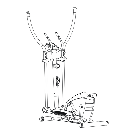
Roger Black Plus Cross Trainer
Assembly & User Instructions-
391/8838
Please Keep for future reference
335/9071
Important –
Please read these instructions fully before assembly or use
These Instructions contain important information which will help you get best from your
equipment and ensure safe and correct assembly, use and maintenance.
If you need help or have damaged or missing parts, call the Customer Helpline: 0345 600 1714
http://www.argos-support.co.uk
Issue 1 -4/10/15
Advertisement
Table of Contents

Related Manuals for Rogerblack 391/8838


Summary of Contents for Rogerblack 391/8838
- Page 1 Roger Black Plus Cross Trainer Assembly & User Instructions- 391/8838 Please Keep for future reference 335/9071 Important – Please read these instructions fully before assembly or use These Instructions contain important information which will help you get best from your equipment and ensure safe and correct assembly, use and maintenance.
-
Page 2: Table Of Contents
Contents Safety Information Components - Parts Components – Fixings Assembly Instructions 5-12 Free area and training area Computer Operation 14-15 Exercise Information . Before Starting . Warning up & Cooling Down 17-19 Care and Maintenance Exploded Parts Diagram Parts List 22-23 Guarantee... -
Page 3: Safety Information
Safety Information Important – Please read fully before assembly or use To reduce the risk of serious injury, read the entire manual before you assemble or operate the Roger Black Cross Trainer. In particular, note the following safety precautions: • Use the equipment only for the intended use, as Assembly described in this manual. -
Page 4: Components - Parts
Components - Parts If you have damaged or missing parts, please 0345 600 1714 call the Customer Helpline: Please check you have all parts listed below Note: Some of the smaller components may be pre-fitted to larger components. Please check carefully before contacting Argos regarding any missing components. -
Page 5: Components - Fixings
Components – Fixings Please check you have all the fixings listed below Note : Please check carefully before contacting Argos regarding any missing fixings. M10x20mm Allen Bolt x 4 Φ10xR34mm Arc Washer x4 Φ10mm Spring Washer x4 M8x15mm Allen Bolt x 4 M8x20mm Allen Bolt x 2 M8x42mm Hex Bolt x 4 Φ8mm Washer x 4... -
Page 6: Assembly Instructions
Assembly Instructions Step 1 a. Attach the Front Stabilizer (3) to the Main Frame (1) using 2 x M10x20mm Allen Bolts (63), 2 x 10mm Spring Washers (77), 2 x 10mmxR34 Arc Washer (81). b. Attach the Rear Stabilizer (4) to the Main Frame (1) using 2 x M10x20mm Allen Bolts (63), 2 x 10mm Spring Washers (77), 2 x 10mmxR34 Arc Washer (81). - Page 7 Assembly Instructions 2(R) 2(L) Step 2 a. Attach the Left Footplate (31L) to the Left Footplate Bar (2L) and secure by 2 x M6 Knob (57); attach the Right Footplate (31R) to the Right Footplate Bar (2R) and secure by 2 x M6 Knob (57). b.
- Page 8 Assembly Instructions 82 78 Step 3 a. Connect the Wire (D1) to the Wire (D2). b. Attach the Front Post (10) to Main Frame (1) and loosely fasten with 4x M8x15mm Allen Bolt (65), 4 x 8mm Spring Washers (78) and 4 x 8mmxR30 Arc Washers (82). c.
- Page 9 Assembly Instructions Step 4 a. Attach the Front Post (10) to the Footplate Bar (2) using 2 x Φ11.5x66mm Allen Bolts (75), and secure with 2 x Φ8mm Washers (83), 2 x M8 Nuts (87). Tighten the bolts from step 3. Attach the Bottle Holder (33) to the Front Post (10) using 2 x ST4.8x15 Dome Head Philips Screw (104).
- Page 10 Assembly Instructions Step 5 a. Attach the Left Linkage Cover (21) and Right Linkage Cover (22) to the Front Post (10), and tighten using 4 x ST4.2x15 Dome Head Philips Screws (103) and 4 x ST4.2x15 Dome Head Philips Screws (102).
- Page 11 Assembly Instructions Step 6 a. Attach the Handles (7L/R) to the Front Post (10) using 2 x M8x42mm Hex Bolts (66), 2 x Φ8xR30mm Arc Washers (82) and 2 x M8 Nuts (87). Notes: The Left Handle (7L) is marked “L”, the Right Handle (7R) is marked “R”.
- Page 12 Assembly Instructions Step 7 a. Attach the Fixed Handle (9) to the Front Post (10) using 2 x M8x20mm Allen Bolts (64), 2 x Φ8mm Spring Washers (78), 2 x Φ8mm Washers (83). b. Remove the two screws on the back of the Computer (41). c.
- Page 13 Assembly Instructions Step 8 a. Attach the Action Arm Cover (27) to the Front Post (10) using 2 x ST4.2x15mm Dome Head Philips Screws (103).
-
Page 14: Free Area And Training Area
Free area and training area The free area must be at least 0.6m greater than the training area in the directions from which the equipment is accessed. The free area is a place should you need to dismount in an emergency. Where two pieces of equipment are positioned adjacent to each other the value of the free area may be shared. -
Page 15: Computer Operation
Computer Operation Functions and operations MODE: Pressing Mode allows you to change the display function on the console. 3. DISTANCE: Press MODE until distance is SET: Press to confirm your target time, distance, displayed. The distance will now be displayed pulse or calories. - Page 16 Computer Operation Specification Auto Scan Every 4 Seconds Speed 0.0 – 99.9 Km/h Distance 0.0 – 999.9 Km Function Time 0:00 – 99:59 (Minute: Second ) Calories 0.0 – 999.9 Cal Odometer 0.0 – 999.9 Km Pulse 40 – 240 BPM Battery type 2 x AA Replacing the batteries...
-
Page 17: Exercise Information
Exercising Information Before starting to exercise How you begin your exercise program depends on your physical condition. If you have been inactive for several years, or are overweight, you must start slowly and increase your time on the equipment; a few minutes per workout increase is advisable. Initially, you may be able to exercise only for a few minutes in your target zone, however, your aerobic fitness will improve over the next six to eight weeks. -
Page 18: Warning Up & Cooling Down
Exercising Information Muscle Chart Aerobic Exercise Aerobic exercise improves the fitness of your lungs and heart - your body’s most important muscle. Aerobic exercise fitness is promoted by any activity that uses your large muscles (arms, legs, or buttock, for example). Your heart beats quickly and you breathe deeply. - Page 19 Exercising Information Warming up and Cooling down exercises Each workout should include the following three parts: 1. A warm-up, consisting of 5 to 10 minutes of stretching and light exercise. A proper warm-up increases your body temperature, heart rate, and circulation in preparation for exercise. 2.
- Page 20 Exercising Information Calf/Achilles stretch With one leg in front of the other, reach forward and place your hands against a wall. Keep your back leg straight and your back foot flat on the floor. Bend your front leg, lean forward and move your hips toward the wall.
-
Page 21: Care And Maintenance
Care and Maintenance Replace defective Examine the equipment Do not attempt to repair components immediately and periodically in order to detect this equipment yourself. keep the equipment out of use any damage or wear. Should you have any difficulty until repair; The safety level of the with assembly, operation or Special attention to... -
Page 22: Exploded Parts Diagram
Exploded Parts Diagram... -
Page 23: Parts List
Exploded Parts List Part Description Qty. Part Description Qty. Main Frame Ø30xØ38x650mm Handle Grip Footplate Bar (L & R) Ø20xØ28x470mm Handle Grip Front Stabilizer Ø22x1.5mm End Cap Rear Stabilizer Ø38x1.5mm End Cap U-Shaped Connector Tension Knob Magnet Bracket Reed Base Handles (L &... - Page 24 Belt Φ15.7x89 Allen Bolt/ End 1/2’’x24(L) Exploded Parts List Part Description Qty. Part Description Qty. Φ15.7x89 Allen Bolt/ End ST4.2X10MM Dome Head Philips Screw 1/2’’x24(R) M10x55mm Allen Bolt M10 Nut M10x20mm Hex Bolt M8 Nut M6x15mm Hex Bolt M10x1.25mm Hex Nut M8x15mm Hex Bolt 1/2’’...
-
Page 25: Guarantee
Guarantee Product Guarantee This product is guaranteed against manufacturing defects from a period of Year This product is guaranteed for twelve months from the date of original purchase. Any defect that arises due to faulty materials or workmanship will either be replaced, refunded or repaired free of charge where possible during this period by the dealer from whom you purchased the unit.
Need help?
Do you have a question about the 391/8838 and is the answer not in the manual?
Questions and answers