
Related Manuals for Sunset Swings 422P


Summary of Contents for Sunset Swings 422P
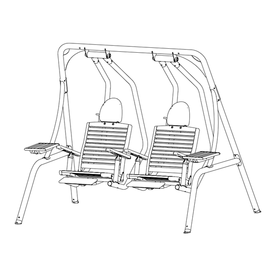
- Page 1 Sunset Swings By Health In Motion ASSEMBLY & OPERATION MANUAL MODEL 422P DUAL RECLINER SWING RECORD SERIAL NUMBER HERE www.sunsetswings.com by Health In Motion 8-17-06 LLC.
- Page 2 422P OWNERS MANUAL READ! VERY IMPORTANT RESIDENTIAL USE ONLY, FOR ADULTS ONLY Caution: Make sure swing has completely stopped before entering or exiting the swing. Be careful as swing may shift while entering or exiting, and while sitting down or getting up from swing seat.
-
Page 3: Table Of Contents
Thank you for choosing Sunset Swings. Please read the contents of this manual thoroughly. The information inside will help you in many different areas. You will need to send in your customer registration card at the back of this manual to validate your warranty. -
Page 4: Positioning Your Swing
Positioning Your Swing The swing is designed to be installed on a level surface. There should be a minimum clearance of four feet in front and back, and two feet on each side of your swing. It should be placed in an area where children will not stray or walk into the path of the swing. -
Page 5: Parts List
Parts List 2…………………Arc Brace 2…………………Footrest Frame 2…………………Footrest Pad 2…………………Footrest Rubber End Cap 2…………………Footrest Sleeve Left 2…………………Footrest Sleeve Right 2…………………Front Leg 2…………………Headrest Assembly (pre-assembled) 2…………………Rear Leg 4…………………Seat Support Arm 2…………………Seat Support Frame 4…………………Swing Foot 1…………………Top Beam 2…………………Wood Seat Assembly (pre-assembled) 2…………………Wood Table Hardware List 4………M5 x ¾”... - Page 6 PAGE 5...
-
Page 7: Arc Brace
Assemble Side Uprights Rear Leg Swing Foot Arc Brace STEP 3 2 - ” x 3 1/4” Carriage Bolt ⅜ 2 - ” Flat Washer ⅜ STEP 2 2 - ” Lock Nut ⅜ 2 - ⅜” x 3” Carriage Bolt 2 - ”... - Page 8 Important: Front of Top Beam must STEP 5 be oriented as shown with the “F” label and Sunset Swings label towards front. ⅜” x 3 1/4” Carriage Bolt 2 - ⅜” Flat Washer - ⅜” Lo k Rotate each side...
-
Page 9: Top Beam
Top Beam Pivot Assembly STEP 6 4 - ⅜” x 2 3/4” Carriage Bolt 4 - ⅜” Flat Washer 4 - ⅜” Lock Nut Seat Support Arms Top Beam Pivot Assembly Seat Support Arms Step 6: Attach Seat Support Arms to the Pivot Four (⅜”... - Page 10 NOTE: Flanges on the Support Arms must be angled inward toward front of swing Seat Support Frame Seat Support Arms STEP 7 4 - ⅜” x 2 3/4” Carriage Bolt 4 - ⅜” Flat Washer 4 - ⅜” Lock Nut Step 7: Attach Seat Support Frame to Seat Support Four (⅜”...
-
Page 11: Wood Seat Assembly (Pre-Assembled)
Wood Seat Assembly Seat Support Frame Wood Seat Assembly od Seat Assembly Seat Support Frame STEP 8 2 - ⅜” x 2” Hex Bolt 4 - ⅜” Flat Washer 2 - ⅜” Lock Nut Step 8: Attach Wood Seat Assembly to Seat Support Step 8: Attach Wood Seat Assembly to Seat Support Two (⅜”... - Page 12 STEP 9 Attach 4 Extension Springs to Seat Support Frames Extension Spring Step 9: Attach all 4 Extension Springs to Seat Support Frames as shown in enlarged view. Page 11...
- Page 13 STEP 10 1 – M5 x ¾” Socket Head Allen Bolt Step 10: Attach Wood Seat Arms to One (M5 x ¾” Socket Head Allen Bolt) Seat Support Frame using: (Thread Socket Head Allen Bolt through Wood Seat Arm hole and Metal Ratchet into Seat Support Frame) Repeat step 10 for all four Wood Seat Arms Wrench tighten, but do not over tighten resulting in seat backs not reclining...
-
Page 14: Wood Table
Arc Brace Wood Table STEP 11 1 - ⅜” x 4 ¾” Hex Bolt 2 - ⅜” Flat Washer 1 - ⅜” Lock Nut Step 11: Attach Wood Table to Arc Brace using: One (⅜” x 4 ¾” Hex Bolt) (Make sure table is flat) Two (⅜”... - Page 15 Head Pad STEP 12 ¼ ” x 1 3/8” Button Head Bolts ¼ ” Flat Washers ” Lock Nuts ¼ Wood Seat Back Step 12: Attach Headrest Assemblies to Two (¼” X 1 3/8” Button Head Bolts) Wood Seat Backs using 4mm Two (¼”Flat Washers) Allen wrenches and: Two (¼”...
- Page 16 STEP 13 4 – 3/8” x 5/8”Hex Bolt 4 – 3/8” Lock Washer STEP 15 2 – ¼” x 2 7/8” Button Head Bolt 4 – ¼” Flat Washer 2 – ¼” Lock Nut Foot Rest Frame Foot Rest Pad Footrest Rubber End Cap Seat Support Frame STEP 14...
- Page 17 Adjustments If headrest rotates too easily or hard, adjust headrest resistance by tightening nut to increase resistance and loosening nut to decrease resistance. Tighten or Loosen Nut Page 16...
-
Page 18: General Maintenance Information
GENERAL MAINTENANCE INFORMATION Wood: Every six months apply teak oil to all areas of the wood top and bottom. Canopy: In freezing climates, the canopy option should be removed, folded and stored in a dry place before the first freeze or snow, and until the last freeze or snow has passed. The canopy option is not designed for high winds. -
Page 19: Warranty Claim Procedure
Sunset Swings warrants this product to the original purchaser to be free from defects in workmanship and/or materials under normal use. If at any time a component part is defective, Sunset Swings shall repair or replace it (at Sunset Swings option) within a reasonable period of time.
Need help?
Do you have a question about the 422P and is the answer not in the manual?
Questions and answers
Need to order replacement parts can’t find the parts list
Need replacement parts for model 422P