Table of Contents
Advertisement
OPERATOR'S AND PARTS MANUAL
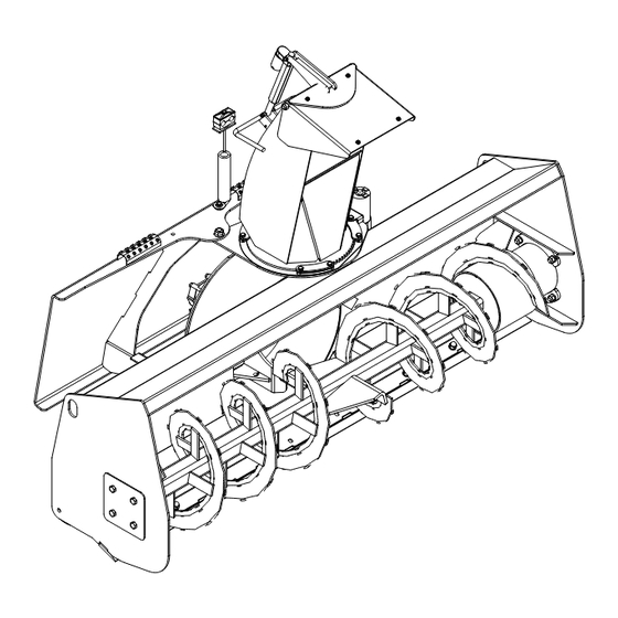
HYDRAULIC SNOW BLOWER
Serial Number: ___________________
Model Number: ___________________
800-456-7100 I www.paladinattachments.com
Manual Number: 51-4694
Models:
STD: 11048, 11060, 11072, 11078 &
HF: 11072, 11078, 11084 & 11096
Release Date: June 2015
Rev. 1
2800 N. Zeeb Rd., Dexter, MI. 48130, United States of America Copyright ©
11084 (A through E)
(F through H)
1
Advertisement
Table of Contents

Related Manuals for FFC 11048

Summary of Contents for FFC 11048
- Page 1 OPERATOR’S AND PARTS MANUAL HYDRAULIC SNOW BLOWER Manual Number: 51-4694 Serial Number: ___________________ Models: STD: 11048, 11060, 11072, 11078 & Model Number: ___________________ 11084 (A through E) HF: 11072, 11078, 11084 & 11096 (F through H) Release Date: June 2015 Rev.
- Page 2 Notes...
-
Page 3: Table Of Contents
TABLE OF CONTENTS PREFACE ..............................4 SAFETY STATEMENTS ..........................5 GENERAL SAFETY PRECAUTIONS......................5-7 EQUIPMENT SAFETY PRECAUTIONS ....................7-8 SAFETY DECALS & LABELS .........................9-10 INSTALLATION ............................11-13 OPERATION ............................14-20 MAINTENANCE ...........................21-22 TROUBLESHOOTING ..........................23 PRODUCT SPECIFICATIONS ........................24 BOLT TORQUE SPECIFICATIONS ......................25 WARRANTY ...............................26 STANDARD FLOW HOUSING ......................28-29 STANDARD FLOW CHUTE ........................30-31 STANDARD HYDRAULICS .........................32-35 STANDARD MOUNTING .........................36... -
Page 4: Preface
PREFACE GENERAL INFORMATION This product was carefully designed and manufactured to give you many years of dependable service. Only minor maintenance (such as cleaning and lubricating) is required to keep it in top working condition. Be sure to observe all maintenance procedures and safety precautions in this manual and on any safety decals located on the product and on any equipment on which the attachment is mounted. -
Page 5: Safety Statements
SAFETY STATEMENTS DANGER! THIS SIGNAL WORD IS USED WHERE SERIOUS INJURY OR DEATH WILL RESULT IF THE INSTRUCTIONS ARE NOT FOLLOWED PROPERLY. WARNING! THIS SIGNAL WORD IS USED WHERE SERIOUS INJURY OR DEATH COULD RESULT IF THE INSTRUCTIONS ARE NOT FOLLOWED PROPERLY. CAUTION! THIS SIGNAL WORD IS USED WHERE MINOR INJURY COULD RESULT IF THE INSTRUCTIONS ARE NOT FOLLOWED PROPERLY. - Page 6 GENERAL SAFETY PRECAUTIONS WARNING! PROTECT AGAINST FLYING DEBRIS Always wear proper safety glasses, goggles or a face shield when driving pins in or out or when operation causes dust, flying debris, or any other hazardous material. WARNING! LOWER OR SUPPORT RAISED EQUIPMENT Do not work under raised booms without supporting them.
- Page 7 GENERAL SAFETY PRECAUTIONS WARNING! DO NOT MODIFY MACHINE OR ATTACHMENTS Modifications may weaken the integrity of the attachment and may impair the function, safety, life and performance of the attachment. When making repairs, use only the manufacturer’s genuine parts, following authorized instructions. Other parts may be substandard in fit and quality.
-
Page 8: Equipment Safety Precautions
EQUIPMENT SAFETY PRECAUTIONS WARNING! REMOVE PAINT BEFORE WELDING OR HEATING. Hazardous fumes/dust can be generated when paint is heated by welding, soldering or using a torch. Do all work outside or in a well ventilated area and dispose of paint and solvent properly. - Page 9 • Replacement parts for parts with safety signs attached must also have safety signs attached. • Safety signs are available, free of charge, from your dealer or from FFC. STANDARD FLOW PLACEMENT OR REPLACEMENT OF SAFETY SIGNS 1. Clean the area of application with non-flammable solvent, and then wash the same area with soap and water.
-
Page 10: Safety Decals & Labels
SAFETY DECALS 4. 50-0727 WARNING! FLYING OBJECTS 3. 50-0724 WARNING! HIGH PRESSURE FLUID 5. 50-0737 WARNING! PINCH POINT 6. 50-10017 WARNING! READ MANUAL 10. RDL3131 RED REFLECTIVE MARKER 13. RDL3163 DANGER! ROTATING FAN 12. RDL3161 DANGER! ROTATING AUGER... -
Page 11: Installation
INSTALLATION & SET-UP WARNING! READ MANUAL PRIOR TO INSTALLATION Improper installation, operation, or maintenance of this equipment could result in serious injury or death. Operators and maintenance personnel should read this manual, as well as all manuals related to this equipment and the prime mover thoroughly before beginning installation, operation, or maintenance. - Page 12 INSTALLATION & SET-UP CAUTION! Failure to obey the following procedures may result in personal injury. • To avoid electrical shock during the wiring harness installation, remove the ground cable from the battery of your prime mover. Remove the ground cable from the negative (-) post of your prime mover's battery. Remove the nut from the POSITIVE (+) cable clamp on the battery and slide the RED wire ring terminal from the wiring harness cable over the positive (+) cable clamp bolt.
-
Page 13: Installation
INSTALLATION & SET-UP READ AND UNDERSTAND ALL SAFETY STATEMENTS Read all safety decals and safety statements in all manuals before beginning any Snow Blower setup. Know and obey all OSHA regulations, local laws, and other professional guidelines for your operation. Know and follow good work practices when assembling, maintaining, repairing, mounting, removing, or operating this equipment. -
Page 14: Operation
OPERATION JOY STICK ILLUSTRATIONS LEFT JOYSTICK RIGHT JOYSTICK Caterpillar Joy Stick Deflector UP: Button A Deflector DOWN: Button B Chute Rotation RIGHT: Button C & Button B Chute Rotation LEFT: Button C & Button A DEFLECTOR UP = BUTTON A DEFLECTOR DOWN = BUTTON B CHUTE ROTATION LEFT = BUTTON C PLUS BUTTON A CHUTE ROTATION RIGHT = BUTTON C PLUS BUTTON B... - Page 15 OPERATION Gehl RT Track Loader Joy Stick Chute Rotation LEFT: Button A Chute Rotation RIGHT: Button B Deflector UP: Button C Deflector DOWN: Button D...
- Page 16 OPERATION JOY STICK ILLUSTRATIONS Case/New Holland Joy Stick Deflector UP: Button A Deflector DOWN: Button B Chute Rotation RIGHT: Button C Chute Rotation LEFT: Button D t t i l , e l t i l e l t l l a o l f Komatsu Joy Stick Deflector UP: Button A...
- Page 17 OPERATION Intended Use This snow blower has been designed and built to push loose snow . Use in any other way is considered contrary to the intended use. Compliance with and strict adherence to operation, service and repair conditions as specified by the manufacturer, are also essential elements of the intended use. READ AND UNDERSTAND ALL SAFETY STATEMENTS Read all safety decals and safety statements in all manuals prior to operating or working on this equipment.
- Page 18 • Using your Snow Blower as a snow "plow" CAN result in damage to this product and WILL void all FFC warranties. Never direct the discharge at buildings, automobiles, trees, or any other item that may be damaged by thrown snow.
- Page 19 OPERATION Hydraulic Snow Blower Operation CAUTION! Failure to obey the following procedures may result in personal injury. • Avoid pinch points and be aware of rotating parts when manually turning fan or auger. e) The fan can then be manually turned in a reverse rotation, allowing the foreign object to be removed.
- Page 20 OPERATION LIFT POINTS Lifting points are identified by lifting decals where required. Lifting at other points is unsafe and can damage attachment. Do not attach lifting accessories around cylinders or in any way that may damage hoses or hydraulic components. •...
-
Page 21: Maintenance
MAINTENANCE READ AND UNDERSTAND ALL SAFETY STATEMENTS Read all safety decals and safety statements in all manuals prior to operating or working on this equipment. Know and obey all OSHA regulations, local laws, and other professional guidelines for your operation. Know and follow good work practices when assembling, maintaining, repairing, mounting, removing, or operating this equipment. -
Page 22: Maintenance
MAINTENANCE READ AND UNDERSTAND ALL SAFETY STATEMENTS Read all safety decals and safety statements in all manuals prior to operating or working on this equipment. Know and obey all OSHA regulations, local laws, and other professional guidelines for your operation. Know and follow good work practices when assembling, maintaining, repairing, mounting, removing, or operating this equipment. -
Page 23: Troubleshooting
TROUBLESHOOTING Problem Possible Cause Possible Solution Auger will not rotate Hoses installed incorrectly Switch quick coupler fittings Hydraulic valve on skid steer not engaged See skid steer operator's manual for auxiliary operation procedure Worn, damaged, insufficient or inadequate pump Repair or replace hydraulic pump Insufficient oil in system Service the skid steer hydraulic reservoir, see skid steer operator's manual... -
Page 24: Product Specifications
PRODUCT SPECIFICATIONS PRIME MOVER SPECIFICATIONS NOTICE! Exceeding any of the maximum recommended prime mover specifications CAN result in damage to this product and WILL void all FFC warranties. DESCRIPTION SPECIFICATIONS All Models All Models All Models Motor Kit (A) Motor Kit (C) (D) or (E) -
Page 25: Bolt Torque Specifications
BOLT TORQUE SPECIFICATIONS NOTE - Nylock nuts are utilized when greater resistance to vibrating loose is required, and greater operating temperatures are not a factor. In addition, like lock nuts, nylock nuts have a safety feature that if the bolt does vibrate loose, the nut will remain on the screw. Install nylock nuts to the standard torque shown above. -
Page 26: Warranty
WARRANTY Limited Warranty Except for the Excluded Products as described below, all new products are warranted to be free from defects in material and/or workmanship during the Warranty Period, in accordance with and subject to the terms and conditions of this Limited Warranty. Excluded Products. - Page 27 NOTES...
-
Page 28: Standard Flow Housing
STANDARD FLOW HOUSING ASSEMBLY... - Page 29 STANDARD FLOW HOUSING ASSEMBLY Item Part Qty Description 07-1763 Washer, Flat, 1/2 SAE, Gr8 07-10126 Washer, Flat, 1 5/8 SAE, Gr5 13-17276 Weld, Auger, Standard (48 inch) 13-51790 Weld, Auger, Standard (60 inch) 13-51789 Weld, Auger, Standard (72 inch) 13-52905 Weld, Auger, Standard (78 inch) 13-51791 Weld, Auger, Standard (84 inch)
-
Page 30: Standard Flow Chute
STANDARD FLOW CHUTE ASSEMBLY... -
Page 31: Standard Flow Chute
STANDARD FLOW CHUTE ASSEMBLY Item Part Qty Description 07-3022 Screw, HHC, Gr8, 1/4-20 x 2 07-3432 Screw, HHC, Gr8, 1/4-20 x 3/4 07-4033 Nut, Hex, Nylock, Gr8, 1/4-20 13-17292 Gear Cover 13-17294 Weld, Chute 13-17487 Plate, Chute, Spacer 13-18453 Rod, .25 x 9.97 13-18454 Plate, 7ga, Retaining, for Chute Rods 13-51119... -
Page 32: Standard Hydraulics
STANDARD HYDRAULIC COMPONENTS 48-60 inch A,C,D,E Series RED WIRE PLUG BROWN WIRE PLUG GREEN WIRE PLUG YELLOW WIRE PLUG... - Page 33 STANDARD HYDRAULIC COMPONENTS 48-60 inch A,C,D,E Series Item Part Qty Description 03-1953 Elbow, 90º, 6MF-10MB 03-2092 Elbow, 90º, 6MB-6MFS 03-2115 Elbow, 45º, 6MB-6MF 03-2126 Elbow, 90º, 10MB-10MF 03-4316 Hose, .25 x 20, 6FFS-6FFS, 3K 03-4372 Tee, 10MF-10MF-10FF 03-5661 Hose, .5 x 36, 10FFS-10FFS, 3.5K 03-5755 Hose, .5 x 100, 10FF-10FF, 4K 03-5843...
- Page 34 STANDARD HYDRAULIC COMPONENTS 72-84 inch D & E Series RED WIRE PLUG BROWN WIRE PLUG GREEN WIRE PLUG YELLOW WIRE PLUG...
-
Page 35: Standard Hydraulics
STANDARD HYDRAULIC COMPONENTS 72-84 inch D & E Series Item Part Qty Description 03-1953 Elbow, 90º, 6MF-10MB 03-2092 Elbow, 90º, 6MB-6MFS 03-2115 Elbow, 45º, 6MB-6MF 03-2126 Elbow, 90º, 10MB-10MF 03-4316 Hose, .25 x 20, 6FFS-6FFS, 3K 03-4372 Tee, 10MF-10MF-10FF 03-5256 Hose, .5 x 51, 10MB-10FFSSLG, 3.5K 03-5755 Hose, .5 x 100, 10FF-10FF, 4K... -
Page 36: Standard Mounting
STANDARD MOUNTING ASSEMBLY Item Part Qty Description 07-7714 Screw, HHC, Gr5, 5/8-11 x 1 1/2 105840 Washer, Fender, .34 x 1.5 x 10ga LAF6535 Weld, Back Plate (Contact Dealer for Correct Model) P851105 Washer, Lock, 5/16 RHW1105 Screw, HHC, Gr5, 5/16-18 x 1 RHW1112 Screw, HHC, Gr5, 5/16-18 x 2.5 RHW1604... - Page 37 NOTES...
-
Page 38: High Flow Housing
HIGH FLOW HOUSING ASSEMBLY Single Motor... - Page 39 HIGH FLOW HOUSING ASSEMBLY Single Motor Item Part Qty Description 07-1177 Clamp, Rubber Coat, 1/2 x 3/4 07-1763 Washer, Flat, Gr8, 1/2 07-3273 Washer, Lock, Split, Medium, 5/16 07-3298 Clamp, Rubber Coat, 1 1/2 x 3/4 07-3436 Screw, HHC, Gr8, 5/16-18 x 3/4 07-10126 Washer, Flat, Gr5, 1.63 13-17284...
- Page 40 HIGH FLOW HOUSING ASSEMBLY Dual Motor...
- Page 41 HIGH FLOW HOUSING ASSEMBLY Dual Motor Item Part Qty Description 07-1177 Clamp, Rubber Coat, 1/2 x 3/4 07-1763 Washer, Flat, Gr8, 1/2 07-3273 Washer, Lock, Split, Medium, 5/16 07-3298 Clamp, Rubber Coat, 1 1/2 x 3/4 07-3436 Screw, HHC, Gr8, 5/16-18 x 3/4 07-10126 Washer, Flat, Gr5, 1.63 13-17324-72 1...
-
Page 42: High Flow Chute
HIGH FLOW CHUTE ASSEMBLY Item Part Qty Description 07-3022 Screw, HHC, Gr8, 1/4-20 x 2 LAF6527 Weld, Deflector LAF6551 Plastic Deflector Liner LAF6565 Liner, Chute, Plastic LAF6566 Chute Rotation Pad LAF6568 Rod, 1.5 x .69, Chute Retainer LAF6599 Weld, Chute P158003 Nut, Elastic Lock, 1/4 RHW1043... -
Page 43: High Flow Mounting
HIGH FLOW MOUNTING ASSEMBLY Item Part Qty Description LAF6594 Weld, Back Plate (Contact Dealer for Correct Model) LAF1421 Gasket, Hose Hole RHW1604 Screw, HHC, Gr5, 5/8-11 x 2 RHW5632 Washer, Flat, Gr5, 5/8 RHW7607 Nut, Top Lock, Flange, Gr8, .63-11... -
Page 44: High Flow Hydraulics
HIGH FLOW HYDRAULIC COMPONENTS F Series... - Page 45 HIGH FLOW HYDRAULIC COMPONENTS F Series Item Part Qty Description 03-1945 Fitting, 12MB-12MFS 03-2092 Elbow, 90º, 6MB-6MFS 03-2177 Elbow, 90º, 12MB-12MFS 03-2182 Elbow, 45º, 12MB-12MFS 03-2291 Fitting, 6MB-6MFS 03-2564 Fitting, 6MF-10MB 03-3135 Tee, 12MB-12MF-12MF 03-6343 Hose, .75 x 80, 12FF-12FF, 4K 03-3390 Hose, .75 x 30, 12FF-12FF90, 100R17 10.
- Page 46 HIGH FLOW HYDRAULIC COMPONENTS G Series...
- Page 47 HIGH FLOW HYDRAULIC COMPONENTS G Series Item Part Qty Description 03-1945 Fitting, 12MB-12MFS 03-1950 Tee, 12MF-12MF-12MB 03-2092 Elbow, 90º, 6MB-6MFS 03-2182 Elbow, 45º, 12MB-12MFS 03-2291 Fitting, 6MB-6MFS 03-2564 Fitting, 6MF-10MB 03-3135 Tee, 12MB-12MF-12MF 03-6343 Hose, .75 x 80, 12FF-12FF, 4K 03-3390 Hose, .75 x 30, 12FF-12FF90, 100R17 10.
- Page 48 HIGH FLOW HYDRAULIC COMPONENTS H Series...
-
Page 49: High Flow Hydraulics
HIGH FLOW HYDRAULIC COMPONENTS H Series Item Part Qty Description 03-1945 Fitting, 12MB-12MFS 03-2092 Elbow, 90º, 6MB-6MFS 03-2182 Elbow, 45º, 12MB-12MFS 03-2291 Fitting, 6MB-6MFS 03-2564 Fitting, 6MF-10MB 03-3135 Tee, 12MB-12MF-12MF 03-6343 Hose, .75 x 80, 12FF-12FF, 4K 03-3390 Hose, .75 x 30, 12FF-12FF90, 100R17 03-3689 Elbow, 90º, 6FF-6MF 10.
Need help?
Do you have a question about the 11048 and is the answer not in the manual?
Questions and answers