Table of Contents
Advertisement
Available languages
Available languages
Quick Links
DIGITALER MATRIX-ROUTER
DIGITAL MATRIX ROUTER
ROUTEUR MATRICIEL NUMÉRIQUE
ROUTER MATRICE DIGITALE
DRM-880 LAN
DRM-880 WP
BEDIENUNGSANLEITUNG • INSTRUCTION MANUAL • MODE D'EMPLOI • ISTRUZIONI PER L'USO
VEILIGHEIDSVOORSCHRIFTEN • CONSEJOS DE SEGURIDAD • ŚRODKI BEZPIECZEŃSTWA
SIKKERHEDSOPLYSNINGER • SÄKERHETSFÖRESKRIFTER • TURVALLISUUDESTA
Best.-Nr. 17.3750
Best.-Nr. 17.3760
Advertisement
Chapters
Table of Contents

Related Manuals for IMG STAGE LINE DRM-880 LAN

Summary of Contents for IMG STAGE LINE DRM-880 LAN
- Page 1 DIGITALER MATRIX-ROUTER DIGITAL MATRIX ROUTER ROUTEUR MATRICIEL NUMÉRIQUE ROUTER MATRICE DIGITALE DRM-880 LAN Best.-Nr. 17.3750 DRM-880 WP Best.-Nr. 17.3760 BEDIENUNGSANLEITUNG • INSTRUCTION MANUAL • MODE D’EMPLOI • ISTRUZIONI PER L’USO VEILIGHEIDSVOORSCHRIFTEN • CONSEJOS DE SEGURIDAD • ŚRODKI BEZPIECZEŃSTWA SIKKERHEDSOPLYSNINGER • SÄKERHETSFÖRESKRIFTER • TURVALLISUUDESTA...
- Page 2 Przed uruchomieniem … Før du tænder … Życzymy zadowolenia z nowego produktu “img Stage Vi håber, du bliver glad for dit nye “img Stage Line” pro- Line”. Prosimy zapoznać się z informacjami dotyczącymi dukt. Læs sikkerhedsanvisningerne nøje før ibrugtag- bezpieczeństwa przed użytkowaniem urządzenia, w ten ning, for at beskytte Dem og enheden mod skader, der sposób zdrowie użytkownika nie będzie zagrożone, a...
- Page 3 ① ② 10 11 ③ ④ Blockdiagramm eines Eingangskanals • Block diagram of an input channel • Diagramme dʼun canal dʼentrée • Schema a blocchi di un canale dʼingresso ⑤ Blockdiagramm eines Ausgangskanals • Block diagram of an output channel • Diagramme dʼun canal de sortie • Schema a blocchi di un canale dʼuscita...
-
Page 4: Table Of Contents
Inhalt Auf der ausklappbaren Seite 3 finden Sie alle beschriebenen Bedienelemente und An - Übersicht der Bedienelemente und Ausgänge konfigurieren ... 10 schlüsse. Anschlüsse ..... 4 6.5.1 Eingangssignale zuweisen /mischen . -
Page 5: Bedieneinheit Drm-880Wp
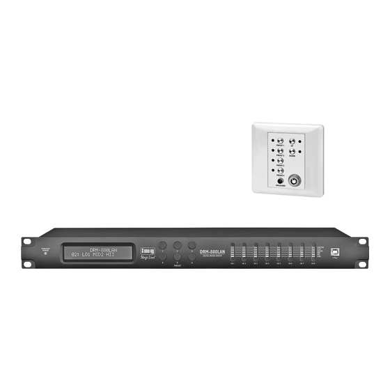
1.3 Bedieneinheit DRM-880WP Funktionen, wie Equalizer, Delays, Rückkopp- der jeweilige Eingang als Mikrofon- oder Line- lungsunterdrückung, Kompressoren und Limi- Eingang konfigurieren ( Kap. 6.4.1). 16 Tasten PRESET 1 – 4 mit Kontroll-LEDs zum ter genutzt werden. Bei der Ansteuerung von Auf alle Mikrofoneingänge gemeinsam lässt Aufrufen der ersten vier Konfigurationen Mehrweg-Lautsprechersystemen kann der DRM-... -
Page 6: Netzanschluss
schlossen werden. Werden mehrere Geräte ver- Die Tasten haben dabei folgende Funktionen: 3) Nacheinander mit den Tasten PRESET 2 und bunden und längere Steuerleitungen verwendet, PRESET 3 die gewünschten Werte in den PRESET 1 sollte der Steuerausgang des letzten Gerätes vier Feldern einstellen und jeweils mit der Aufruf eines Untermenüs und Bestätigung der Kette zur Vermeidung von Störungen bei der... -
Page 7: Schaltkombination Abrufen
5.3.4 Schaltkombination abrufen SIGNAL – leuchtet für einen Ausgang, wenn an 2) Die Tasten UP und DOWN (18) gedrückt hal- einem ihm zugewiesenen Eingang ein Signal ten und die Stromversorgung wieder an - Über das Menü lassen sich auch die gespei- anliegt schließen. -
Page 8: Geräte Hinzufügen
6.2.1 Geräte hinzufügen – die Netzwerkeinstellungen am Computer 6.2.7 Gerätekonstellation laden sind nicht korrekt (bei Verbindung über Um ein (weiteres) Gerät hinzuzufügen, auf die Zum Laden einer zuvor auf dem Computer Ethernet) Schaltfläche „Add Device“ klicken. gespeicherten Gerätekonstellation: Ein verbundenes Gerät zeigt auf seinem Display 1) Rechts oben im Fenster auf die Schaltfläche Ist USB als aktuelle Schnittstellenart gewählt z. -
Page 9: Programm Beenden
eine eigene ID-Nummer oder IP-Adresse zuge- wiesen bekommen. Dies kann über das System- Menü geschehen ( Kap. 5.3.1 bzw. 5.3.3) oder, wie im Folgenden beschrieben, über den Computer. Die Geräte dazu nacheinander über USB an den PC anschließen und jeweils die folgenden Ein- stellungen vornehmen: 1) Wenn nicht aktuell die USB-Schnittstelle gewählt ist, im Hauptfenster zur USB-Schnitt-... -
Page 10: Verstärkung
Durch erneutes Klicken auf die Schaltfläche „Show cursor“ werden die Bezugspunkte wieder ausgeblendet. 6.4.6 Rückkopplungsunterdrückung (FBK) Ist für einen Eingang als Signalpegel „Mic“ ge - wählt, kann alternativ zur Klangregelung unter „Sel Fbk/ EQ“ die Funktion „FBK“ gewählt werden (Abb. 14). Hierbei handelt es sich um einen wir- kungsvollen Algorithmus zur Unterdrückung von Rückkopplungen auf der Basis einer Frequenz- verschiebung. -
Page 11: Signalverzögerung
6.5.2 Signalverzögerung Jedes Ausgangssignal kann bis zu 380,998 ms verzögert werden. Dadurch können z. B. Schall- laufzeitunterschiede bei verschiedenen Laut- sprecherabständen ausgeglichen werden. In der Ansicht für einen Ausgang (z. B. „Out- put1“, Abb. 18) lässt sich unter „Delay“ die Ver- zögerung für das Ausgangssignal einstellen. -
Page 12: Verstärkung
2) Mit dem Regler „Ratio“ das Kompressions- gestellten Kompressionsgrad abhängige Erhö- 6.7 Stummschaltung verhältnis einstellen. Dabei bedeutet z. B. ein hung des Ausgangspegels zulässt, legt der Über die Schaltflächen „Mute In“ lassen sich die Kompressionsverhältnis von 10 : 1, dass sich Schwellwert des Limiters die absolute Ober- Eingänge, über „Mute Out“... -
Page 13: Einstellungen Kopieren
6.9 Einstellungen kopieren 6.11 Verwaltung der Konfigurationen 2) Im Feld „Select Position“ oder durch Klicken auf einen Eintrag in der Liste unter „Memory Die über das Steuerprogramm erstellten Konfi- Im Gegensatz zur Kopplung der Kanäle, bei der Program“ den Speicherplatz wählen. Es kann gurationen können auf sechs Speicherplätzen nur die während der Kopplung geänderten Para- ein freier Speicherplatz „Program Empty“... -
Page 14: Schaltausgänge
6.12 Schaltausgänge Die eingegebenen Namen werden auf dem 6.13 Schalteingänge Computer gespeichert. Die vier im Gerät gespeicherten Extra-Konfigu- Zum Einstellen der Schaltausgänge rechts oben rationen können durch externe Schaltsignale im Konfigurationsfenster auf die Schaltfläche aufgerufen werden. Den Schalteingängen kön- „Switch“ klicken. Es öffnet sich das Dialogfenster nen zudem unterschiedliche Prioritäten zugeteilt „Switch“... -
Page 15: Schnittstellenmodus Wählen
Beispiel: 7 Technische Daten Alle Eingänge sind für die Umschaltung zugelassen. Es ist als Logikart „active High“ gewählt und „Configure DRM-880LAN Priority“ = 3 eingestellt, d. h. die Rangfolge der Ein- gänge ist laut Tabelle S1, S4, S3, S2. Daraus folgt: Frequenzbereich: . -
Page 16: Operating Elements And Connections
Contents All operating elements and connections de - scribed can be found on the fold-out page 3. 6.4.6 Feedback suppression (FBK) ..22 Operating Elements and Connections 16 6.4.7 Phase reversal ....22 Front panel . -
Page 17: Control Panel Drm-880Wp
1.3 Control panel DRM-880WP Ten configurations may be saved on the unit 4.2 Amplifiers or other units and be retrieved when required: six via the but- Connect the amplifiers, monitoring systems or 16 Buttons PRESET 1 – 4 with indicating LEDs tons on the unit, four by external control via the other units for further signal processing to the for retrieving the first four configurations... -
Page 18: Mains Connection
Note: For a direct Ethernet connection to the computer, 5.3.2 Selecting an interface a crossover cable is required. The interfaces USB and RS-485 cannot be used To control multiple DRM-880LANs via RS-485 or at the same time. To select the interface: Ethernet, an individual IP address or ID number 1) Call up the menu. -
Page 19: Linking Switching Combinations To Configurations
5) Press the button PRESET 1 to go to the com- least 512 MB, 10 MB free hard-disk space and a tion) and the unit number (ID) must be 1 ( chapters bination selected. USB, Ethernet or RS-485 interface. The screen 5.3.2 and 5.3.3). -
Page 20: Connecting Or Disconnecting Units
If Ethernet is selected as the current interface 6.2.4 Calling up the configuration window 2) Under “Select Connection”, select the inter- type (the text on the button on the upper left is face desired (“USB”, “RS485” or “TCP/ IP”). To operate a connected unit by remote control “TCP/ IP”), the following dialog window will ini- and to change its configuration, click the button 3) For “RS485”, the number of the port used for... -
Page 21: Exiting The Program
7) Use the button “Disconnect” to disconnect the data connection and then confirm the confirmation message. If desired, connect another DRM-880LAN to the USB port of the computer and continue with step 3. Then go to the interface desired for controlling and configuring the units ( chapter 6.2.8). -
Page 22: Frequency Response
6.5.2 Signal delay Each output signal may be delayed by up to 380.998 ms. Thus, different sound delay times due to different speaker distances may be bal- anced. In the view of an output (e. g. “Output1”, fig. 18), under “Delay”, set the delay for the output signal. The unit (meter or milliseconds) can be changed in the view “Overview”... -
Page 23: Frequency Response
6.5.4.1 Frequency response The diagram in the upper section of the window indicates the frequency response of the output channel, depending on the equalization and gain chapter 6.5.6) that have been set. In the upper right of the diagram, the type of representation can be selected: magnitude fre- quency response (“Mag”) or phase frequency response (“Phase”). -
Page 24: Phase Reversal
2) Use the slider “Attack [ms]” to adjust the to all input channels linked. Only the parameters 2) Under “Output Source”, select the output attack time. changed while the linkage was active are whose adjustments are to be copied. adopted by the other channels. All individual 3) Use the slider “Release [sec]”... -
Page 25: Loading Configurations
6.11.2 Loading configurations 6.11.4 Loading configurations from the unit from the computer To retrieve a configuration saved on the DRM- CAUTION Prior to loading a configuration, 880LAN and to load it onto the computer: check if it corresponds to the units 1) On the upper right of the window, click the connected. -
Page 26: Loading A Switching Combination
By default, the subfolder “Preset” is 6.13.2 Selecting the logic type (high / low) 6.14 Selecting the interface mode selected which was automatically created Similar to the procedure in the system menu, it is Under “Active Mode”, define if the switchover is during program installation. -
Page 27: Specifications
7 Specifications DRM-880LAN Frequency range: ..20 – 20 000 Hz ±1 dB Audio inputs Input voltage: ..6.2 V (max.) Impedance: ..10 kΩ Connections: . -
Page 28: Face Arrière
Table des matières Ouvrez le présent livret page 3, dépliable, de manière à visualiser les éléments et branche- Eléments et branchements ..28 6.4.5 Egaliseur (EQ) ....34 ments. -
Page 29: F Bch
1.3 Unité de commande DRM-880WP 3 Possibilités dʼutilisation 4.1 Sources de signal Reliez les sources de signal avec niveau ligne, Le DRM-880LAN est un routeur matriciel de 16 Touches PRESET 1 – 4 avec LEDs de par exemple la sortie dʼun préamplificateur ou signaux avec 8 entrées analogiques dont les contrôle pour appeler les quatre premières dʼune table de mixage aux bornes à... -
Page 30: Ordinateur
4.6 Ordinateur 5.3 Réglages système Pour régler lʼadresse IP : Pour appeler le menu pour les réglages sys- 1) Appelez le menu. Le sous-menu souhaité est Pour une gestion à distance du DRM-880LAN tème, maintenez la touche PRESET 5 (3) enfon- via un ordinateur, reliez-le à... -
Page 31: Appeler Une Combinaison De Commutation
4) Avec les touches PRESET 2 et PRESET 3, 5.4 LEDs dʼétat 5.5.1 Réglage de lʼunité de commande sélectionnez le numéro souhaité dʼappareil La LED PHANTOM POWER (1) brille si lʼali- Pour régler lʼunité de commande sur le DRM- (1 – 64). mentation fantôme pour les entrées micro est 880LAN : activée. -
Page 32: Ajouter Des Appareils
6.2.1 Ajouter des appareils Un appareil relié indique sur son affichage par 6.2.7 Charger une constellation dʼappareils exemple Pour ajouter un (autre) appareil, cliquez sur le Pour charger une constellation dʼappareils préa- bouton “Add Device”. lablement mémorisés sur lʼordinateur : System Lock Connection 1) Cliquez en haut à... -
Page 33: Quitter Le Programme
Reliez les uns après les autres les appareils via USB au PC et effectuez les réglages suivants : 1) Si lʼinterface USB nʼest pas sélectionné, pas- sez dans la fenêtre principale sur lʼinterface USB ( chapitre 6.2.8). 2) Ajoutez une appareil (“Add Device”, cha- pitre 6.2.1). -
Page 34: Amplification
Le niveau du déplacement de fréquence se règle via le réglage “Input Feedback Speed %”. Plus la valeur est élevée, plus lʼélimination du larsen est efficace. 6.4.7 Inversion de phase Le signal dʼune entrée peut être inversé. Cela peut par exemple contrer des effacements de phase si deux micros se trouvent dans des direc- tions différentes ou avec un éloignement diffé- rent avec la même source sonore. -
Page 35: Filtres Passe-Haut Et Passe-Bas
réglée. Le bouton devient rouge. Pour réactiver la temporisation, cliquez sur le bouton à nou- veau. 6.5.3 Filtres passe-haut et passe-bas Chaque sortie dispose de filtres passe-haut et passe-bas qui, combinés, peuvent remplir la fonction dʼun filtre de fréquences (pour une répartition selon la fréquence dʼun signal dʼen- trée sur deux ou plusieurs canaux de sortie). -
Page 36: Amplification
selon les réglages du compresseur. La réper- 3) Avec le réglage “Release [sec.]”, réglez la 6.8 Couplage des canaux cussion dʼune modification des paramètres durée de réinitialisation cʼest-à-dire la durée Si certains paramètres doivent être réglés à “Threshold”, “Ratio” ou “Soft/ Hard Knee” est visi- jusquʼà... -
Page 37: Copie Des Réglages Dʼune Entrée
6.9.1 Copie des réglages dʼune entrée 6.11.1 Mémoriser une configuration sur 4) Pour mémoriser, cliquez sur le bouton “Store” lʼordinateur ou interrompez le processus avec “Cancel”. 1) Cliquez sur le bouton “Input Copy”. La fenê- Pour mémoriser la configuration actuelle sur lʼor- tre de dialogue “Input Copy”... -
Page 38: Renommer Les Sorties De Commutation
Les combinaisons de commutation 7 à 10 6.12.3 Mémoriser une combinaison de 6.13.1 Libérer ou verrouiller des entrées commutation sur lʼordinateur sont reliées aux configurations extra 1 à 4 Sous “External Signal Enable” déterminez quels chapitre 6.11.5), elles sont appelées via les 1) Via les boutons –... -
Page 39: Sélection Du Mode Dʼinterface
6.14 Sélection du mode dʼinterface 7 Caractéristiques techniques Comme dans le menu système, on peut sélec- tionner si une des interfaces USB ou RS-485 DRM-880LAN doit être définie manuellement ou automatique- ment reconnue par lʼappareil. Bande passante : ..20 – 20 000 Hz 1) Dans le bas de la fenêtre de configuration ±1 dB sous “USB/ RS485”, cliquez sur “Setup”. -
Page 40: Elementi Di Comando E Collegamenti
Indice A pagina 3, se aperta completamente, vedrete tutti gli elementi di comando e i collegamenti Elementi di comando 6.4.5 Regolazione toni (EQ) ... . . 46 descritti. e collegamenti ....40 6.4.5.1 Risposta in frequenza . -
Page 41: Unità Di Comando Drm-880Wp
1.3 Unità di comando DRM-880WP feedback, compressori e limiter. Nella gestione Per tutti gli ingressi per microfoni si può di sistemi di altoparlanti a più vie, il DRM- impostare cosi anche unʼalimentazione phantom 16 Tasti PRESET 1 – 4 con LED di controllo per 880LAN può... -
Page 42: Collegamento Con La Rete
dovrebbe essere collegata con un terminatore PRESET 4 IP = 127.0.0.1 a IP = 191.255.255.255 ⇒ maschera di rete = FFFF0000h (classe B) (resistenza 120 Ω fra pin 1 e 2 del contatto). Annullamento di un input, uscita dal menù o Per il comando remoto dellʼapparecchio via da un sottomenù... -
Page 43: Accoppiare Le Combinazioni Di Commutazione Con La Configurazione
4) Con i tasti PRESET 2 e PRESET 3 scegliere se lʼalimentazione dellʼunità di comando viene 6.1 Installare il software per il PC la combinazione desiderata (1 – 10). Il attivata prima del DRM-880LAN. La configurazione minima per lʼinstallazione del numero della combinazione scelta lampeggia programma in dotazione è... -
Page 44: Collegare O Separare Degli Apparecchi
legge “TCP/ IP”), si vede dapprima la seguente 6.2.3 Dare un nome allʼapparecchio 6.2.8 Cambiare lʼinterfaccia finestra: Per cambiare uno dei tre tipi dʼinterfaccia sup- Per distinguere meglio più apparecchi nella fine- portati, occorre dapprima eliminare tutti gli appa- stra principale, si possono dare dei nomi agli recchi dalla finestra principale ( Cap. -
Page 45: Terminare Il Programma
3) Collegare lʼapparecchio (“Connect”, Cap. 6.2.2). 4) Cliccare sul pulsante ora disponibile “ID & IP”. Si apre la seguente finestra: ⑫ Finestra “Configure ID-RS485 and IP Address” ⑬ Visualizzazione “Overview” 5) Per il telecomando tramite RS-485, alla voce “Select new ID” stabilire un numero ID (1 – 64). N. -
Page 46: Amplificazione
6.4.6 Soppressione del feedback (FBK) Se per un ingresso è stato scelto il livello “Mic”, in alternativa alla regolazione toni, alla voce “Sel Fbk/ EQ” si può scegliere la funzione “FBK” (Fig. 14). Si tratta di un algoritmo efficace per soppri- mere il feedback tramite lo spostamento della frequenza. -
Page 47: Ritardo Dei Segnali
6.5.2 Ritardo dei segnali Ogni segnale dʼuscita può essere ritardato fino a 380,998 ms. Così si possono compensare p. es. le differenze nel percorso del suono in caso di distanze differenti degli altoparlanti. Nella visualizzazione per unʼuscita (p. es. “Out- put1”, Fig. -
Page 48: Amplificazione
stare il relativo regolatore con il mouse, oppure 6.5.7 Limitazione del livello (Limiter) con il regolatore selezionato, spostarlo sulla Il Limiter serve per limitare velocemente il tastiera per mezzo dei tasti freccia o dei tasti di segnale entro un livello preimpostato. Così, per scorrimento. -
Page 49: Copiare Le Impostazioni
6.9 Copiare le impostazioni 6.11 Gestione della configurazione gliere la locazione di memoria. Si può sce- gliere una locazione libera “Program Empty” Le configurazioni realizzate tramite il pro- Contrariamente allʼaccoppiamento dei canali oppure una già occupata per sovrascrivere il gramma di comando possono essere salvate in dove cambiano solo i parametri modificati suo contenuto. -
Page 50: Uscite Di Commutazione
6.12 Uscite di commutazione 6.12.2 Salvare la combinazione di 6.13 Ingressi di commutazione commutazione nellʻapparecchio Le quattro configurazioni extra memorizzate nel- Per impostare le uscite di commutazione, in alto 1) Tramite i pulsanti – scegliere una com- lʼapparecchio possono essere aperte tramite a destra della finestra di configurazione cliccare binazione di commutazione che deve essere segnali esterni di commutazione. -
Page 51: Scegliere Il Modo Dʻinterfaccia
7 Dati tecnici DRM-880LAN Gamma di frequenze: ..20 – 20 000 Hz ±1 dB Ingressi audio Tensione dʻingresso: . . . max. 6,2 V Impedenza: ..10 kΩ Contatti: . - Page 52 Lees aandachtig de onderstaande veiligheids- voorschriften, alvorens het toestel in gebruik te ne men. Mocht u bijkomende informatie over de bediening van het toestel nodig hebben, lees dan de En gelse tekst van deze hand lei ding. Veiligheidsvoorschriften Dit apparaat is in overeenstemming met alle ver- 2.
- Page 53 Przed użyciem urządzenia należy przeczytać uważnie poniższą instrukcję obsługi i zachować tekst do wglądu. Więcej informacji dotyczących obsługi urządzenia znajduje się w innych wers- jach językowych niniejszej instrukcji obsługi. Środki bezpieczeństwa Urządzenie spełnia wymogi norm obowiązują- wolno zasłaniać otworów wentylacyjnych w ności za błędną...
- Page 54 Läs igenom säkerhetsföreskrifterna innan enhe- ten tas i bruk. Ytterligare information återfinns på övriga språk i manualen. Säkerhetsföreskrifter Enheten uppfyller samtliga Eu-direktiv och har Rengör endast med en mjuk och torr trasa, därför försett med symbolen an vänd aldrig kemikalier eller vatten vid ren- göring.
- Page 55 ® MONACOR INTERNATIONAL GmbH & Co. KG • Zum Falsch 36 • 28307 Bremen • Germany © Copyright by MONACOR INTERNATIONAL. All rights reserved. A-1400.99.01.08.2013...
Need help?
Do you have a question about the DRM-880 LAN and is the answer not in the manual?
Questions and answers