Table of Contents
Advertisement
SERVICE
WASHING MACHINE (DRUM)
Refer to the service manual in the GSPN (see the rear cover) for the more information.
WASHING MACHINE
DRUM TYPE
Basic Model : WF455ARGSGR/A2
(GRACE-S PROJECT)
Model Name : WF45H6300AG
WF22H6300AG
WF45H6300AW
WF45H6100AP
(WF6000HA)
Model Code : WF45H6300AG/A2
WF22H6300AG/AX
WF45H6300AW/A2
WF45H6100AP/A2
(WF6000HA)
Manual
1. Safety Instructions
2. Features and Specifications
3. Disassembly and Reassembly
4. Troubleshooting
5. PCB Diagram
6. Wiring Diagram
7. Reference
CONTENTS
Advertisement
Table of Contents
Troubleshooting

Related Manuals for Samsung WF455ARGSGR/A2


Summary of Contents for Samsung WF455ARGSGR/A2
-
Page 1: Washing Machine
WASHING MACHINE DRUM TYPE Basic Model : WF455ARGSGR/A2 (GRACE-S PROJECT) Model Name : WF45H6300AG WF22H6300AG WF45H6300AW WF45H6100AP (WF6000HA) Model Code : WF45H6300AG/A2 WF22H6300AG/AX WF45H6300AW/A2 WF45H6100AP/A2 SERVICE (WF6000HA) Manual WASHING MACHINE (DRUM) CONTENTS 1. Safety Instructions 2. Features and Specifications 3. Disassembly and Reassembly 4. -
Page 2: Table Of Contents
CONTENTS 1. Safety instructions ..............1 1-1. -
Page 3: Safety Instructions
1. SAFETy INSTRuCTIONS 1-1. SAFETy INSTRuCTIONS FOR SERvICE ENGINEERS ► Be sure to observe the following instructions to operate the product correctly and safely to prevent possible accidents and hazards while servicing. ► Two types of safety symbols, Warning and Caution, are used in the safety instructions. Hazards or unsafe practices that may result in severe personal injury or death. WARNING Hazards or unsafe practices that may result in minor personal injury or property damage. CAuTION WARNING BEFORE SERvICING... - Page 4 CAuTION BEFORE SERvICING • Do not sprinkle water onto the washing machine directly when cleaning it. √ This may result in electric shock or fire, and may shorten the product lifetime. • Do not place any containers with water on the washing machine. √ If the water is spilled, it may result in electric shock or fire. This will also shorten the product lifetime. • Do not install the washing machine in a location exposed to snow or rain. √ This may result in electric shock or fire, and shorten the product lifetime. • Do not press a control button using a sharp tool or object. √ This may result in electric shock or damage to the product. CAuTION WHILE SERvICING • When wiring a harness, make sure to seal it completely so no liquid can enter. √ Make sure that they do not break when force is exerted. • Check if there is any residue that shows that liquid entered the electric parts or harnesses. √ If any liquid has entered into a part, replace it or completely remove any remaining moisture from it. • If you need to place the washing machine on its back for servicing purposes, place a support(s) on the floor and lay it down carefully so its side is on the floor. √ Do not lay it down on its front. This may result in the inside tub parts damaging. 2 _ Safety Instructions...
- Page 5 WARNING WHILE SERvICING • Check if the power plug and outlet are damaged, flattened, cut or otherwise degraded. √ If faulty, replace it immediately. Failing to do so may result in electric shock or fire. • Completely remove any dust or foreign material from the housing, wiring and connection parts. √ This will prevent a risk of fire due to tracking and electrical hazard. • When connecting wires, make sure to connect them using the relevant connectors and check that they are completely properly. √ If tape is used instead of the connectors, it may cause fire due to tracking. • Make sure to discharge the PBA power terminals before starting the service. √ Failing to do so may result in a high voltage electric shock. • When replacing the heater, make sure to fasten the nut after ensuring that it is inserted into the bracket-heater. √ If not inserted into the bracket-heater, it touches the drum and causes noise and electric leakage. WARNING AFTER SERvICING • Check the wiring. √ Ensure that no wire touches a rotating part or a sharpened part of the electrical harness. • Check for any water leakage. √ Perform a test run for the washing machine course and check whether there is any water leakage through the floor section or the pipes. • Do not allow consumers to repair or service any part of the washing machine themselves. √ This may result in personal injury and shorten the product lifetime.
- Page 6 CAuTION AFTER SERvICING • Check the assembled status of the parts. √ Now is a good time to inspect your work. Review all connections and wiring, including mounting hardware. • Check the insulation resistance. √ Disconnect the power cord from the power outlet and measure the insulation resistance between the power plug and the grounding wire of the washing machine. The value must be greater than 10MΩ when measured with a 500V dC Megger. • Check whether the washing machine is level the floor with respect to the original position of the washing machine prior to service. By doing this now will reduce for the need of customer dissatisfaction and redo call. √ Vibrations can shorten the lifetime of the product. 4 _ Safety Instructions...
-
Page 7: Features And Specifications
2. FEATuRES AND SPECIFICATIONS 2-1. FEATuRES Features Description The Largest Capacity • Samsung’s extra-large capacity laundry machine can wash a full set of your Bedding PLUS, a kingsize comforter, or up to 31 bath towels in a single load. Since you don’t have to do as many loads, you save time, money, water and energy. 8” LCD Touch Screen • The brilliant 8” Color LCD Touch Screen displays cycle information, settings, Display options, and more. The easy-to-use interface allows you to scroll through all wash cycles with the slightest touch. Smart Control • Samsung’s innovative Smart Control technology enables you to control your washer through personal technologies such as smart phones. You don’t have to be on standby until the cycle ends. Smart Control allows you to monitor the washing process and let you know when the cycle is complete. Smart Care • Samsung’s Smart Care, an automatic error-monitoring system, detects and diagnoses problems at an early stage and provides a quick and easy solution through LCD navigation. With the innovative Smart Control technology, you can also be alerted when the problem occurs via your smart phones. PowerFoam™... - Page 8 Features Description Pedestal with Storage • An optional 15” pedestal is available to raise the washer Drawers for easier loading and unloading. (Model No : WE357*) It also offers a built-in storage drawer that can hold a 100 oz. bottle of detergent. • Samsung washers and dryers can be stacked to Stacking (Model No : SK-5A/XAA) maximize usable space. An optional stacking kit is available for purchase from your Samsung retailer. 6 _ Features and Specifications...
-
Page 9: Specifications
2-2. SPECIFICATIONS WF45H6300AG WF45H6300AW Model WF45H6100AP WF22H6300AG Wash type FRONT LOADING WASHER A: High-Overall 38.7”984mm B: Width 27”(686mm) Dimension (Inches / mm) C: Depth with door open 90º 51.7”(1,314mm) D: Depth 34’’(863.7mm) Water pressure 20 ~ 116psi(137~800kpa) Weight 105kg(231.5lb) Heater Rating 900 W Washing 120 V 200 W Washing and Heating 120 V... -
Page 10: Comparing Specifications With Existing Models
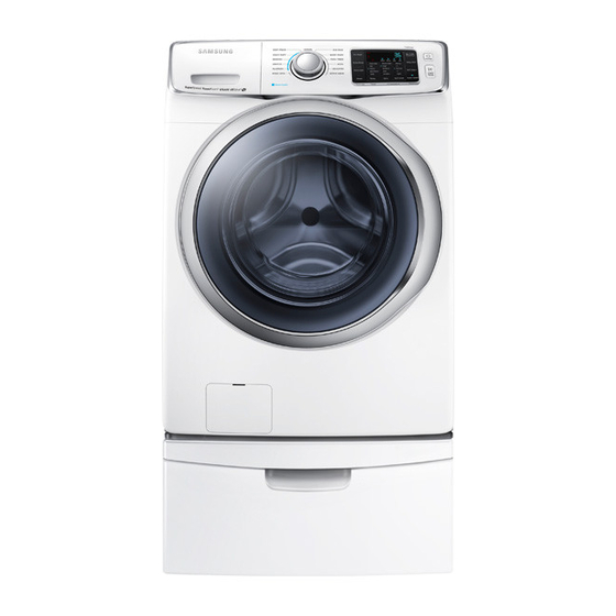
2-3. COMPARING SPECIFICATIONS WITH EXISTING MODELS Project WF6000HA BEST WF6000HA BEST GRACE S WF45H6300AG Model Name WF45H6300AW WF22H6300AG WF455ARGSGR WF45H6100AP Image Capacity (cu.ft. IEC) 4.5 cu.ft 22kg 5.2 cu.ft Motor type dd Motor dd Motor dd Motor MAX rPM 1300 1300 1300 Yes (VRT+) -
Page 11: Options Specifications
2-4. OPTIONS SPECIFICATIONS Item Code Remarks BOLT-SPANER dC60-40146A Default (Wrench) ASSY HOSE WATER DC97-15648A Default ASSY HOSE WATER DC97-15648B Default MANUAL USER dC68-03385B Default CAP-FIXEr dC67-00307A Default HoSE-HANgEr dC62-10278A Default Note • Customer can purchase additional water supply and drain hoses from a service center. • The spanner(wrench), water supply and drain hoses are not supplied. Both the water supply and drain hoses are supplied during the installation. Features and Specifications _ 9... -
Page 12: Disassembly And Reassembly
3. DISASSEMBLy AND REASSEMBLy 3-1. TOOLS FOR DISASSEMBLy AND REASSEMBLy Tool Type Remarks 10mm Heater (1) Socket Wrench with 13mm Motor (1), Balance (5), 2 holes of each left and 6” Extension right of the shock absorber 1 Pulley hole 19mm 10mm Replaceable for the box driver. Open End 13mm Since the bolt runs idle when the box driver is wrench used, use the box driver 17mm. 19mm Tool to protect the idle and abrasion of the bolt Vice pliers for the box driver. Others General tools for the after service. (Driver, Nipper, Long nose) 10 _ Removal and Reassembly... -
Page 13: Standard Disassembly Drawings
3-2. STANDARD DISASSEMBLy DRAWINGS ► This is a standard disassembly diagram and may differ from the actual product. Use this material as a reference when disassembling and reassembling the product. Part Figure Description 1. Remove the 2 screws holding the Back-Cover at the back of the washing machine and separate the Back-Cover pushing it downwards. (Assemble it by lifting it upwards) 2. After separating the Back-Cover, remove the M19 nut holding the Motor. To remove it, turn it counter-clockwise. As the Motor also rotates if the nut is turned slowly, torque it quickly and firmly in a single action. Do not remove the nut by inserting a screwdriver into the Motor, as this may result in a problem with the motor. 3. Remove the M19 nut and washer and then separate the Rotor. Since removing the rotor requires a lot of strength due to the magnetic force of the Rotor and it may come off suddenly, your hand or arm may be injured by the edge of the Stator or Frame. Disassembling and Therefore take precaution when separating it. Repairing the Rear You can separate the connector by pressing the Motor navel of the Housing and pulling it outside. Motor wire 4. Separate the Motor Wire and Hall Sensor while pressing the navel of the Housing. - Page 14 Part Figure Description 1. Remove the 2 hexagon screws, which are at the back, fixing the COVER-TOP. 2. Disassemble the COVER-TOP by sliding it backwards and remove the 4 screws on the PANEL-CONTROL. Separating the Cover_Top and 3. With the top cover removed you will now have Panel-Control access to service the Water pressure sensor, EMI (Check Main-PCB Noise Filter, Hot and Cold Water Valves, Steam and Sub-PCB) ASSY, Hose Draw ASSY, And main PCB ASSY. 4. Press the Separate button to separate the ASSY Drawer. 5. Disassemble the HOUSING-DRAWER frome the PANEL-CONTROL (push back and then push Housing-drawer upside to separate). 12 _ Removal and Reassembly...
- Page 15 Part Figure Description 6. Pull the PANEL-CONTROL towards and then lift it upwards to separate. Separating the Cover_Top and 7. Carefully disconnect the three wiring connectors by Panel-Control hand. (Check Main-PCB and Sub-PCB) 8. Remove the all screws holding the PCB and 592-493* Assy Panel Control release the hooks on both sides to remove the PCB for repair / replacement. 592-493* Assy Panel Control Removal and Reassembly _ 13...
- Page 16 Part Figure Description 1. Remove the 2 screws holding GUIDE-PCB(M) at BRACKET-SPRING(R). 2. Separate 2 Hooks. Separating the Main 3. Open COVER-PCB(M). 4. Disconnect All Connectors on main PBA. 5. Lift up Main PBA, Change SVC Part. After SVC, Certainly check the all Hooks on COVER-PCB(M) Otherwise COVER-PCB(M) will be disassembled during washing machine running. 14 _ Removal and Reassembly...
- Page 17 Part Figure Description 1. Remove the 2 screws holding the HINGE-DOOR and the FRAME-FRONT. 2. Disassemble the ASSY DOOR lifting it up slightly. 3. Remove the 10 screws fixing the HOLDER- GLASS. (including the 2 blue screws holding the LEVER- DOOR, including the 3 arrow screws holding the HINGE-DOOR.) 4. Putting and pressing hard a flat-head screwdriver into the furrow between COVER-DOOR and Disassembling and SuPPort-HINgE. Reassembling the Door Part 5. Making a semicircle with screwdriver. (Disassemble the hooks) 6. Disassemble the HOLDER-GLASS from COVER- DOOR Take the DOOR-GLASS , SUPPORT- HINGE, HINGE-DOOR. * Check Points for Troubleshooting • Check the status of the screws holding the Hinge (check if they are loose). Check if the front and rear of the door and the hinge part are not damaged. Removal and Reassembly _ 15...
- Page 18 Part Figure Description 1. Pull the DIAPHRAGM upside, and finfish disassembling along the circle. 2. Remove the 2 screws to separate the DOOR LOCK S/W. Disassembling the 3. Remove the 4 screws at the top of FRAME- Front Cover/Frame FroNt. front (check the Door Lock S/W) 4. Push the lever and pull it towards to open the COVER-FILTER. 5. Separate the remaining WATER REMOVAL HOSE (BLUE) from the hook. 6. Remove the 2 screws down under Frame Front. 7. Separate the FRAME-FRONT. 16 _ Removal and Reassembly...
- Page 19 Part Figure Description 1. Remove the Top Assy-Plate. 2. Disconnect the water supply valve wire connector. Disassembling and 3. Remove the 4 screws holding the water supply Repairing the Water valve. Supply valve 4. Remove the hose connected to the valves. (Use the plier to remove the hose.) 1. Separate the wire connected the SENSOR- PrESSurE. 2. Adjust the plastic clip( of pressure sensor) between two nose of plier, then grip and pull the plastic clip with caution. (Use the long nose plier to push the hook). Disassembling and Repairing the Water Level Sensor 3. Remove the hose from the SENSOR-PRESSURE. Disassembling the • Hold the Clamp of the Detergent Box and disassemble the Hose-Drawer-Tub.
- Page 20 Part Figure Description 1. Remove the 2 Cover pump. 2. Separate the Clamp of the hose connected to the PUMP and then pull the DRAIN-HOSE. 3. Separate the Clamp of the hose connected to the Disassembling the PUMP and then pull the HOSE-AIR. Pump Motor Part 4. Separate the Clamp of the hose connected to the PUMP and then pull the HOSE-DRAIN. 5. Separate the wire connected to the PUMP. • If the washing machine works, drain the water in the wash tub by selecting the Spin course. Removing the If the washing machine does not work, remove Remaining Water the laundry from the wash tub and scoop the remaining water out of the tub using a cup. 18 _ Removal and Reassembly...
- Page 21 Part Figure Description 1. Remove the 2 screws fixing GUIDE-WIRE, 6 screws fixing FRAME-PLATE(U). 2. Remove the 3 bolts fixing WEIGHT BALANCER and then pull it towards with caution. Disassembling the 3. Remove the 4 bolts fixing DAMPER to take ASSY tuB out. 4. Remove all wire and hose connected the ASSY- tuB. 5. Open the cap of SPRING-HANGER to take ASSY- tuB out. 6. Lift the ASSY-TUB with two people carefully with holding SPRING-HANGER. Removal and Reassembly _ 19...
- Page 22 Part Figure Description Disassembling the 7. Remove the M10 bolt from the middle of the TUB and separate the TUB-FRONT and TUB-BACK. 1. Separate the ASSY DRUM from TUB, remove 6 M10 bolts from the upper ASSY DRUM, disassemble the ASSY FLANGE SHAFT. 2. Remove 12 screws from the outer sides and Disassembling the then remove the two upper and lower BALL DRuM BALANCERS. 3. Remove 3 screws from the outer sides and then remove the 3 DRUM-LIFTERS. 20 _ Removal and Reassembly...
- Page 23 Part Figure Description 1. Disassemble the Front-Frame. 2. Separate the connection wire. - Separate the Thermostat fixed at the bottom of the Tub. (Take precaution as there may be water remaining.) Make sure to separate the Thermostat first and then separate the Heater. If you fail to observe this order, it may result in a shock and be damaged. 3. Release the nut holding the Heater with an M10 tool and then separate the Heater. Do not completely release the nut. Separating the Pull the Heater forward after releasing the nut. If Heater at the Bottom the Heater is damaged, it may cause a problem. Front Therefore unfasten the nut using spanner or wrench manually without using pincers or tweezers. When you re-assembly the heater, make sure to install the Heater exactly onto the Bracket inside the Tub. If it is not properly installed, it may cause a fire. In addition, completely insert the packing part into the Tub when assembling it so that the packing part is completely attached onto the Tub. Check Points for Troubleshooting 1. Check if the resistance of the Heater is equal to 27.1Ω (for the 1900W product), or 26.2Ω...
-
Page 24: Troubleshooting
4. TROuBLESHOOTING 4-1. ERROR MODES ► This is a washer integrated error mode. For detailed information, refer to the general repair scripts. Error Type For uSA Causes Remarks - The part of the hose where the water level sensor is located is damaged (punctured). - The hose is clogged with foreign material. - The hose is folded. - Too much lubricant has been applied to the insertion part of the Water Level air hose. Sensor - Hose engagement error. (disengaged) - Part fault. (Faulty internal soldering) - Page 25 Error Type For uSA Causes Remarks - Check the consumer’s power conditions. : Make sure to check the operating voltage. Connect a tester to the internal power terminals during the Boil or Dry operations and observe the washing machine’s operation carefully. Power Error 9E1,9E2 : Check the voltages. (An error occurs when under or over voltage is supplied.) : Check whether a plug receptacle is used. When the connecting wire is 1m, a momentary low voltage may drop up to 10 V - Main PBA fault (sometimes) - The signals between the sub and main PBAs are not sensed because of commuication error. - Check the connector connections between the sub and main PBAs carefully. → Check for incorrect or loose connections, etc. - Remove the sub PBA C/Panel and check for any faulty soldering. - The signals between The DR Module and main PBAs are not sensed because of commuication error. - Check The connector connections between The DR Module and main PBAs carefully.
- Page 26 Error Type For uSA Causes Remarks - A switch contact error because of a deformation of the door When the door is not hook. opened after the door open operation. - When the door is pulled by force. When the door is not - This occurs in the Boil wash because the door is pushed due locked after the door to a pressure difference from internal temperature changes. Door Error close operation. - The door lock switch terminal is connected incorrectly. - The door lock switch terminal is broken. - This occurs intermittently because of an electric wire leakage - Main PCB fault. - The washing heater is short-circuited or has a wire disconnected. - The washing heater in the tub has an error. If the heater has no (Contact error, temperature sensor fault) error, this occurs Heater Error HE,HE1 - If the water level sensor operates without water because water because of a PBA relay...
- Page 27 Error Type For uSA Causes Remarks - Error detected in the Mems PBA or data error detected. Check the wire connections. Mems PBA Error Replace if necessary. Detected 1. Check the wire connections. 2. Replace the Mems PBA. System Error - Micro Controller Operation Fail. Replace Assy PCB. Troubleshooting _ 25...
-
Page 28: Corrective Actions For Each Error Code
4-2. CORRECTIvE ACTIONS FOR EACH ERROR CODE 26 _ Troubleshooting... - Page 29 Troubleshooting _ 27...
- Page 30 28 _ Troubleshooting...
- Page 31 Troubleshooting _ 29...
- Page 32 30 _ Troubleshooting...
-
Page 33: Pcb Diagram
5. PCB DIAGRAM 5-1. MAIN PCB ► This Document can not be used without Samsung’s authorization. Location Part No. Function Description Location Part No. Function Description Smart dispenser Connection Supply power to the dispenser PBA and provides a CN11 PBA Power Supply Supply 120V of AC power. Port communications function. Main Relay Be Supplied PBA power when the Power button is pressed. Supply power to the sensor and provides a communications Sensor Connection Port function. Dry Heater Relay The switch for the Dry Heater power. Supply power to the LCD PBA and provides a communications LCD PBA Connection Port function. Washing Heater Relay The switch for the Washing Heater power. -
Page 34: Circuit Diagrams Of Main Parts For Main Pcb
5-2. CIRCuIT DIAGRAMS OF MAIN PARTS FOR MAIN PCB ► This Document can not be used without Samsung’s authorization. ► CN6 ► CN3 1. Ground 1. 3.3V 2. Door SW signal 2. CS1 ► CN9 3. Leakage signal 3. CS2 1. 3.3V 4. DRY_AIR_TEMP signal 4. Sdo 2. rX_FroM_tESt 5. DRY_CON_TEMP signal 5. SP1 3. -
Page 35: Inverter Pcb
5-3 INvERTER PCB ▶ This Document can not be used without Samsung’s authorization. Location Part No. Function Description Communication Communication with MAIN Hall Sensor Sensing Hall signal Motor output MOTOR 3-Phase Output AC Power Source Supply AC Power JtAg Connector Debugging connector (Deleted in massproduction) Flash Writing Port Writing Flash memory PCB Diagram _ 33... -
Page 36: Circuit Diagrams Of Main Parts For Inverter Pcb
5.4. CIRCuIT DIAGRAMS OF MAIN PARTS FOR INvERTER PCB ► This Document can not be used without Samsung’s authorization. ► CN2 ► CN6 ► CN1 1. 5V 1. MAIN Communications signal 1. Motor signal (U) 2. HALL A sensor signal 2. Motor signal (V) 2. MAIN Communications signal 3. HALL B sensor signal 3. Motor signal (W) 3. Ground 4. Ground ► CN5 1. L line 2. N line... -
Page 37: Sub Pcb
5-5. SuB PCB ► This Document can not be used without Samsung’s authorization. Location Part No. Function Description Buzzer Circuit Be generated sound when the menu key is pressed or the encoder is operated, the menu is closed. CN601 SENSor INPut SENSOR THE WATER LEVEL AND WATER TEMPERATURE. CN701 Drum Light Turn on when door is opened. CN401 FLASH WRITING WrItINg ProgrAMME to SuB. CN201 grAPHIC PBA Connection Port For communications with Graphic PBA. CN402 touCH PBA CoMMuNICAtIoN SUPPLY POWER TO TOUCH PBA AND COMMUNICATION TO SUB PBA PCB Diagram _ 35... -
Page 38: Circuit Diagrams Of Main Parts For Sub Pcb
5-6. CIRCuIT DIAGRAMS OF MAIN PARTS FOR SuB PCB ► This Document can not be used without Samsung’s authorization. ► CN601 1. Empty Pin 7. Led Signal 2. Led Signal 8. Led Signal 3. Led Signal 9. Led Signal 4. Led Signal 10. grouNd 5. Led Signal 11. JOG Signal 6. Led Signal 12. JOG Signal 13. Empty Pin ► CN201 1. Communications Port(Rx) 2. Communications Port(Tx) 3. Reset Signal input 4. 5V 5. -
Page 39: Wiring Diagram
6. WIRING DIAGRAM 6-1. WIRING DIAGRAM ► This Document can not be used without Samsungs authorization. ■ REFERENCE INFORMATION BLACK BLUE grEEN GRAY NATURAL orANgE PINK SKYBLU SKYBLUE VIOLET WHItE YELLOW Wiring Diagram _ 37... -
Page 40: Reference
7. REFERENCE 7-1. WF6000HA PROJECT NAME MODEL NAME IN THE MARKET BOM MODEL CODE ► Region or Type ► Color ► Buyer Code ► Drum Machine Classification ► Capacity A : N.America W:WHITE WF:Drum-Washer(Big size) G:Gray 7.5 kg = 75 L : L.America WW:Drum-Washer(Standard) S:SILvER 20 kg = 20 E : Euro WD:Drum-Combo 4.5 cuft = 45... - Page 41 This Service Manual is a property of Samsung Electronics Co.,Ltd. © 2014 Samsung Electronics Co.,Ltd. All Any unauthorized use of Manual can be punished under applicable rights reserved. International and/or domestic law. 14 Nov. 2014...