Advertisement
Quick Links
Operation Manual
Model: Wireless Socket Receiver Module
Wireless Socket Receiver Module
Item No.: WMR-3500
S
pecification:
Function:
On / Off
Frequency:
433.92MHz
Remote distance: 50 meters (open field)
Input rating: 220-240V~50Hz
Output rating: 16Amps / 3500W (Resistive Load)
WMR-3500
Advertisement

Related Manuals for Kappa WMR-3500

Summary of Contents for Kappa WMR-3500
- Page 1 Operation Manual Model: Wireless Socket Receiver Module Wireless Socket Receiver Module Item No.: WMR-3500 WMR-3500 pecification: Function: On / Off Frequency: 433.92MHz Remote distance: 50 meters (open field) Input rating: 220-240V~50Hz Output rating: 16Amps / 3500W (Resistive Load)
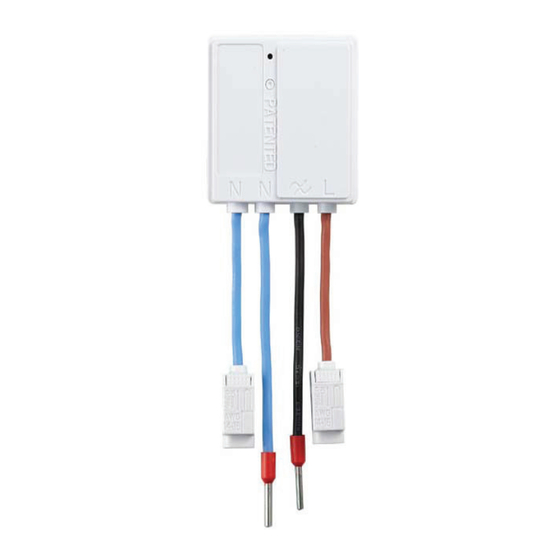
- Page 2 ① Neutral Wire – Blue ② Neutral Wire – Blue ③ Switch Wire – Black ④ Live Wire – Brown imension: verview: Unique miniature high power (16A) receiver module that can replace existing house hold wired wall socket into wireless remote controllable socket. Small compact size for installation into wall box.
- Page 3 nique Difference: Current wall socket is wired with Live / Neutral / Earth directly into the socket terminal. Adding extra receiver module to make your existing wall socket with wireless feature.
- Page 4 iring: Before commencing work, ALWAYS isolate the mains power supply and switch off the circuit breaker. Strip the solid wires (rigid conductor only) at least 10mm then connect the wires as per diagrams below, ensure terminals are properly tightened and no bare wire is visible. Suitable wire size for terminal clamp is 1.6mm to 2.5mm 1.
- Page 5 2. Connect AC Live-in & Neutral-in into each terminal clamp. 3. ① Twist both terminal clamps to the side of module receiver. ② Flip module around with back side facing towards you.
- Page 6 4. The antenna is located on the back side of receiver module. To avoid interference of antenna reception do not cover receiver module with any bare wires. 5. Gently install receiver module into back box.
- Page 7 6. Connect AC Live-out & Neutral-out wires into wall socket terminals. 7. Tidy wires and install wall socket making sure no bare wires are in front of the module receiver.
- Page 8 8. Connect back mains power supply. 9. LED indicator will light ON for 10 seconds, this is to show you that the wires are connected correctly and power is active. 10. To remove wires from terminal clamp, simply push back and pull out the wires...
- Page 9 Each clamp has 2 terminals. When the wires need to be looped, for example to another wall socket. Install the wires shown in the below diagram. airing: Receiver module can pair with up to 6 different remote controls at any one time as it has a maximum of 6 memories.
-
Page 10: Operation
Using a remote control press the ‘ON’ button intended to be paired; the LED will flash twice to confirm that the remote control is now paired. NOTE: Learning Mode lasts for 12 seconds; if no signal is received from a remote control during this time then the receiver module will automatically exit learning mode without pairing the device. -
Page 11: Troubleshoot
roubleshoot: Problem: I cannot pair my remote control with the receiver module. Solution: The memory on receiver is full, please delete one or more memory and try pairing again.
Need help?
Do you have a question about the WMR-3500 and is the answer not in the manual?
Questions and answers