
Related Manuals for Prodys ProntoNet LC


Summary of Contents for Prodys ProntoNet LC
-
Page 1: User Manual
ProntoNetLC User Manual ProntoNetLC User Manual Ver 5.4.1.2 interstage Phistersvej 31, 2900 Hellerup, Danmark Telefon 3946 0000, fax 3946 0040 www.interstage.dk - pro audio with a smile... -
Page 2: Table Of Contents
Index Index ................2 CE Declaration of Compliance..........7 Introduction............... 8 Installation Guide ...............10 II.1 Initial checks ............... 10 II.2 Installation ................. 10 II.3 The rear panel ..............10 II.3.1 Power ................11 II.3.2 Ethernet port – the LAN Connector ......... 11 II.3.2.1. - Page 3 III.2.2.7. Screen 7: GPIO and Serial Port bit rate........ 27 III.2.3 The BOOK Key..............28 THE MENU ................29 IV.1 The Controls: Navigation keys ..........29 IV.2 Main Menu ................. 29 IV.3 NET: Selecting a communications port........30 IV.4 ENC: Encoder algorithm selection menu ........30 IV.4.1 Configuration of Encoder 1 ..........
- Page 4 Remote Control ..............55 V.1 General Configuration ............62 V.1.1 Interfaces ..............63 V.1.1.1. LAN port..............63 V.1.1.2. ISDN Terminal adaptor Configuration........68 V.1.1.3. X21 Port ..............70 V.1.1.4. RS232 Ports ..............70 V.1.1.5. GPIO Port ..............71 V.1.2 Audio Configuration............74 V.1.3 System Configuration ............
- Page 5 VI.6.4 MULTI-UNICAST ............. 119 VI.6.5 Prodys Proprietary set of protocols........120 VI.6.6 Proprietary (set of protocols) v2 ......... 121 VI.6.7 PRODYS PORTS for Prodys Proprietaty protocols (v1 & v2) ..123 VI.7 SIP................. 124 VI.8 SAP................126 VI.9 ProntoNetLC operating as an ISDN codec ........128 VI.9.1 Establishing ISDN calls .............
- Page 6 VI.13.2 When connecting two audiocodecs in unicast, there is no audio at one end................144 VI.13.3 No audio when connecting two audiocodecs using Multicast..144 VI.13.4 Interruptions to audio when connecting two Prodys Codecs..144 Technical Specifications............. 147 VII.1 Audio Interfaces..............147 VII.2 Compression ..............
-
Page 7: Ce Declaration Of Compliance
CE168X parking are in compliance with Electromagnetic Compatibility Directive (89/336/EEC), and the Low Voltage Directive (72/23/EEC) of the European Union. A “Declaration of conformity” for ProntoNetLC is available on file at Prodys offices in Spain. To obtain this information, contact with sales@prodys.net. CAUTION ProntoNetLC uses a Lithium battery. -
Page 8: Introduction
Chapter I Introduction ProntoNetLC expands the PRODYS IP range of audio codecs family. It is based ProntoNetLC on the features provided in ProntoNet. is a multi-algorithm stereo audio codec over IP, supporting many industry standard coding algorithms such as; G722, MPEG1/2 LayerII, MPEG1/2 LayerIII as well as uncompressed linear audio (PCM). - Page 9 This chapter is a practical guide to help in understanding just how the ProntoNetLC unit works under different configurations, especially the more unusual ones. Appendix A – Technical Specifications. Appendix B – Disconnection Codes. This appendix describes the meaning of the disconnecting codes showed on the display.
-
Page 10: Installation Guide
Before unpacking unit check its packaging for any signs of damage or mishandling during transportation. Report any damage to the shipping company immediately. Unpack the unit carefully, if you find any damage or the unit does not work correctly, you should contact Prodys or its distributor as soon as possible. II.2 Installation The ProntoNetLC is designed to be housed in a standard 19”... -
Page 11: Ii.3.1 Power
II.3.1 Power On the back panel you will find the main power inlet. You will also find the main power switch and the fuse holder. The ProntoNetLC unit is designed to take AC universal power, from 100 to 240 VAC with frequency between 50Hz and 60Hz. You will also find a fuse holder that holds two fuses, one for each phase of input. -
Page 12: Ii.3.2.1. Isdn Port (Optional)
Connection to a PC In some cases, such as when you configure the equipment, it is possible that you will want to connect the unit directly to a PC. In this case the PC must have a free Ethernet port to connect to and you must use a ‘cross- over’... -
Page 13: Ii.3.2.2. X21 Port
The NT1 interface is optional and is not supplied as standard. When the ProntoNetLC is connected to a basic rate interface with bus configuration and the unit is the termination point, it must be loaded with 100 Ohm resistors. These may be already fitted in the connection socket, if you do not have external termination, the ProntoNetLC has jumpers available internally that can be set to terminate the ISDN line. -
Page 14: Ii.3.3 Rs 232 Ports
X21 ProntoNet V35 Signal Transmit Data TxD- Transmit Data TxD+ Receive Data RxD- Receive Data RxD+ Clock - Clock+ II.3.3 RS 232 Ports There are two RS232 ports for use as auxiliary data ports. These ports allow the transmission and reception of data along with encoded audio. Port A is always ready. -
Page 15: Ii.3.4 Gpio Port
ProntoNetLC – Pin 7 connector RJ45......Pin 2 PC ProntoNetLC – Pin 2 connector RJ45......Pin 3 PC ProntoNetLC – Pin 3,6 connector RJ45......Pin 5 PC The ProntoNetLC ignores hardware handshaking signals. II.3.4 GPIO Port A Sub-D 25 ways socket provides a general purpose connection with 7 inputs and 7 outputs. -
Page 16: Ii.3.4.1. Inputs
AES/EBU OUT + AES/EBU OUT - This is the default factory configuration. The maximum level on the inputs/outputs can be configured to +4, +18 or +22dBu by setting some jumpers on the audio boards. Contact support@prodys.net for more information. ProntoNetLC User Manual... -
Page 17: Ii.3.6 Microswitches
II.3.6 Microswitches There are 8 microswitches on the back panel which are reserved for special functions. Before turning on the unit the user must check that they are configured according to the following diagram, which is the standard start-up configuration: Switch number 7 will restore the default factory configuration. -
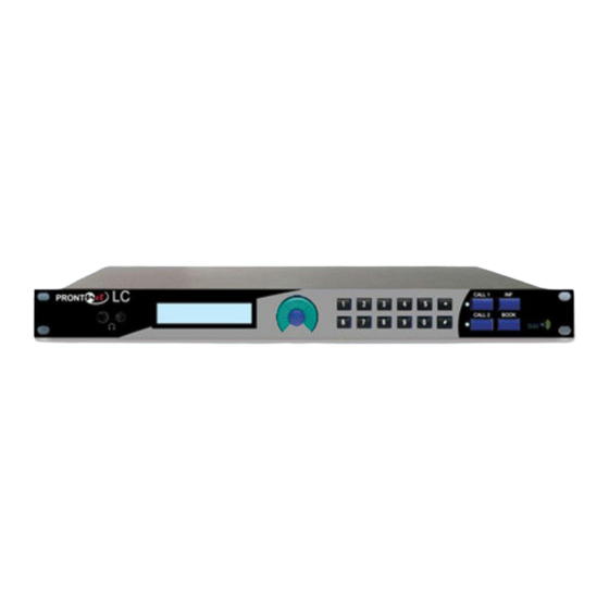
Page 18: The Front Panel
Chapter III The Front Panel The front panel of the ProntoNetLC has a display and keypads that allow you to control and configure the unit. The keys are laid out in the following manner: Navigation Keys: The keys ⇐ ⇐ ⇐ ⇐ , ⇑ ⇑ ⇑ ⇑ , ⇒ ⇒ ⇒ ⇒ , are used for moving around the menus and the OK is for selecting/accepting the desired action or parameter. - Page 19 The display will show information in the following way: TX-> CONNECTED Status RX: CONNECTED FRAMED Status Tx Decoder 1 Line 1 The first line shows information about the status of communication Line 1 (Tx), and the second line shows information about the status of communication Line 1 (Rx), followed by the status of the decoder of line 1.
- Page 20 SEARCH Searching for synchronisation. The displays shows the word “SEARCH”: L1:CONNECTED SEARCH L2:DOWN The Decoder status information only appears if the line is connected. If the line is showing an IDLE status, an indicator code will show the cause of the last disconnection below.
- Page 21 When ProntoNetLC is configured to IP Multi-Unicast , the format of the messages will be the following: DOWN: The communication line is not physically detected. Most likely the interface is not plugged in. The Display shows “DOWN”: TX:_ _ _ _ _ _ _ _ _ _ _ RX:DOWN IDLE: The line is detected physically but no connection is being made.
-
Page 22: Iii.2 Control Keys
III.2 Control Keys III.2.1 The CALL 1 and CALL 2 keys The fundamental role of these keys is the initiation and termination of a connection. Note that these keys have different functions depending on the communication line status at any given moment. Additionally, the display will also show different information. -
Page 23: Iii.2.1.1. Establishing A Call When Prontonetlc Is Configured As An Ip Codec
III.2.1.1. Establishing a call when ProntoNetLC is configured as an IP codec Pressing CALL 1 the screen will display the following: L A N L 1 M O D E { M U L T I C A S T } U N I C A S T The user must select beforehand if the IP communication type is MULTICAST mode (point to multi-point) or UNICAST mode (point to point). -
Page 24: Unicast Codec (Net = Ip)
L A N L 1 M O D E { T x } R x L A N L 1 D I A L 1 0 . 0 . 0 . 0 To make the connection press OK. “Period” is selected with the # key. III.2.1.2. -
Page 25: Iii.2.2 The Inf Key
III.2.2 The INF key This key allows the user a simple and quick way to display detailed information on the status and configuration of the ProntoNetLC. Given that the screen is not able to display all the information at once, you can cycle through the different information screens by repeatedly pressing the INF button, or by using the left and right directional arrows. -
Page 26: Iii.2.2.3. Screen 3: Decoding Algorithm
III.2.2.3. Screen 3: Decoding algorithm This window shows the algorithm that is selected and synchronised for Decoder 1 and 2 (number 2 is only relevant when ProntoNetLC is working as a DUAL codec). Here are some examples: D 1 : M P L 2 - 0 6 4 - M N - 4 8 D 2 : G 7 2 2 D 1 : M P L 2 - 6 4 - S T - 4 8 D 2 : N O T A V A I L A B L E... -
Page 27: Iii.2.2.5. Screen 5: Lan Port Configuration Parameters
If the Encoder is configured to automatic mode or if the Decoder is not synchronised you will see the following: E 1 : A U T O E 2 : N O T A V A I L A B L E III.2.2.5. -
Page 28: Iii.2.3 The Book Key
III.2.3 The BOOK Key This key directly accesses the internal Address Book. By pressing this key we can view and connect to entries in the Address Book. (Note that to edit or modify entries the user has to go into the BOOK option in the main menu). Pressing BOOK the user can enter the Address Book index: <... -
Page 29: The Menu
Chapter IV THE MENU By pressing OK on the navigation keys you enter the system’s main menu from the default STATUS screen. We shall take a close look at the different options available in the system menu. To aid in this, we recommend the reader to have it handy the hierarchical menu tree in the appendices of this manual. -
Page 30: Iv.3 Net: Selecting A Communications Port
INF: From here you can obtain information on the software version and various configuration parameters of the communication port. IV.3 NET: Selecting a communications port. The ProntoNetLC has one communication port as default: IP. X21 interface can be provided under license. N E T S E L E C T I O N { I P } X 2 1 The NET option is only available if the lines are not already connected. -
Page 31: Iv.4.1 Configuration Of Encoder 1
IV.4.1 Configuration of Encoder 1 The configuration of Encoder 1 is done in steps, starting with the selection of an algorithm and following on with the different parameters that relate to that particular algorithm. The ProntoNetLC menu will always only display the options and parameters that are relevant to each algorithm’s configuration. -
Page 32: Iv.4.2 Pcm
IV.4.2 The configuration steps are: 1. Mode: MONO or STEREO. 2. Number of bits: 16,20 or 24 (available since 3.0.8 version). 3. Sample rate: 32 , 48 KHz. S E T E N C O D E R 1 > > A U T { P C M } G 7 1 1 G 7 2 2 P C M S E T M O D E M O N O { S T E R E O }... -
Page 33: Iv.4.5 Mpeg Layer Ii
IV.4.5 MPEG Layer II The configuration steps are: 1. Bit rate. 2. Mode: MONO, JOINT STEREO, STEREO or DUAL. 3. Sample rate: 48, 32 or 24 KHz 4. CRC validation on/off. 5. Auxiliary data on/off. S E T E N C O D E R 1 >... -
Page 34: Iv.4.6 Mpeg Layer Iii
NOTICE – MPEG Layer II RESTRICTIONS If the Bit rate > 128 Kbps a 24 Khz sample rate is not possible. If the Bit Rate > 192 Kbps MONO mode is not possible. IV.4.6 MPEG Layer III The configuration steps are: 1. -
Page 35: Iv.4.7 Aac 2,4 Lc
NOTICE - MPEG Layer III RESTRICTIONS 384 Kbps is not an option with MPEG Layer III. If the Bit rate > 128 Kbps a 24 Khz sample rate is not possible. IV.4.7 AAC 2,4 LC The configuration steps are: 1. Bit rate. 2. -
Page 36: Iv.4.8 Aac Ld
NOTICE: AAC LC RESTRICTIONS If the Bit rate > 128 Kbps the combination MONO - Fs= 24 KHz is not possible. If the Bit Rate > 192 Kbps the combination MONO - Fs= 32 KHz is not possible. If the Bit Rate > 256 Kbps the combination MONO is not possible. If the Bit Rate >... -
Page 37: Iv.4.9 Aac He
A A C S E T A U X D A T A O N { O F F } NOTICE - AAC LD RESTRICTIONS If NET = ISDN Bit Rate > 128 Kbps is not possible. If the Bit Rate >256 Kbps, a 24 KHz sample rate is not possible. IV.4.9 AAC HE The configuration steps are: 1. -
Page 38: Iv.4.10 Apx
A A C S E T A U X D A T A O N { O F F } IV.4.10 The aptX menu allows the selection of Standard aptX or Enhanced aptX. < < S E T E N C O D E R 1 > > A C 4 L C A A C 4 L D { A P T X } S E T E N C O D E R A P T - X { S T D A P T X } E N H A P T X... -
Page 39: Iv.4.12 Enh Aptx
These are the available options: a) 64 Kbps Mono 7.5 KHz. b) 128 Kbps Stereo 7.5 KHz o Mono 15 KHz. c) 192 Kbps Mono 20 KHz. d) 256 Kbps Stereo 15 KHz. e) 384/576 KHz Stereo 20 KHz. IV.4.12 ENH APTX The configuration steps are: 1. - Page 40 NET = IP: Mode apt-X Enhanced 16 bits 20 bits 24 bits 16 kHz 7.5 mono 64 kbps 16 kHz 7.5 stereo 128 kbps 32 kHz 15 mono 128 kbps 160 Kbps 192 kbps 32 kHz 15 stereo 256 kbps 320 kbps 384 kbps 48 kHz...
-
Page 41: Iv.5 Configuration Of Encoder 2
IV.5 Configuration of Encoder 2 NOTICE – ENCODER2 RESTRICTIONS Only available if NET = IP and Double Mode is set. Only G722 mode is available over IP. For the Encoder 2 the following options are available: AUT : Automatic Mode. This means that the Encoder adopts the same mode as the Decoder. -
Page 42: Iv.6 Conf: General Configuration Menu
IV.6 CONF: General configuration Menu Grouped here are all the general parameters. These are usually configured during installation it is not normally necessary to reconfigure afterwards. They are grouped in the following way: C O N F M E N U { A U D } P O R T S S Y S B O O K AUD: This selects between the analog and digital audio inputs. -
Page 43: Iv.6.1.2. Audio Levels
AES/EBU If we select AES/EBU next we will see a screen where it will be possible to select the sync type – internal (with the digital audio input) or external (coming from another device connected to the AES/EBU connector). C O N F A E S / E B U S Y N C { A U D I O } E X T AES/EBU TRANSPARENT The AES/EBU TRANSP is a special transmission mode for PCM 24 bits digital... -
Page 44: Iv.6.2.1. Lan
IV.6.2.1. L A N P O R T C O N F { I P } D H C P E T H P O R T S IP: Manually setting of IP parameters. DHCP: Automatic IP configuration from a DHCP server. ETH: Ethernet port speed and duplex configuration. - Page 45 This option allows the user to set the web server port, and the base port of the TCP/UDP port group used for audio, data and control. For more information about setting TCP/UDP ports, please read chapter VI.6.7 – Prodys ports. P O R T S C O N F...
-
Page 46: Iv.6.2.2. Isdn
IV.6.2.2. ISDN S E T I S D N P O R T { N E T } L I N E 1 L I N E 2 NET: From here we select the ISDN protocol. LINE1: For configuring the ISDN parameters for communication Line 1 (one of the two B channels of the ISDN interface). - Page 47 SPID: When you are using NAT1 or DMS100 you must enter the correct Service Profile ID (SPID) numbers for the ISDN BRI circuit. Automatic or manual response: When automatic response is selected, the unit will connect automatically to an incoming call, always doing so when there is no restriction imposed by the local number or other such call filters.
-
Page 48: For Line 2 The Options Are Laid Out In The Same Way
SPID: L I N E 1 S P I D N U M B E R ANS: L I N E 1 A N S W E R M O D E M A N U A L { A U T O } LOOP: L I N E 1 E X T . -
Page 49: Iv.6.3 Conf-Sys
< < S E T R S 2 3 2 P O R T A 1 2 0 0 2 4 0 0 4 8 0 0 9 6 0 0 Port B is only available if the unit is working as a DUAL codec , i.e. -
Page 50: Iv.6.3.2. Pll
IV.6.3.2. This is a special option that allows you to select the PLL reference clock when NET = IP. S E T P L L { I P } X 2 1 IV.6.3.3. To enable/disable the fan. F A N M E N U { O F F } A U T In AUT mode fan is temperature controlled and will switch itself on and off automatically as required. -
Page 51: Iv.6.3.5. Keypad
There is only one GPIO interface for two decoders (if the second is available) so the user has to configure which decoder will carry the GPIO information. G P I O D A T A M E N U { O F F } D E C 1 D E C 2 IV.6.3.5. -
Page 52: Iv.6.3.6. Ipcodec
A L L K E A Y P A D U N L O C K L E D IV.6.3.6. IPCODEC There are two different operation modes: SIMPLE and DOUBLE mode. In SIMPLE mode, the unit will work as usual, that means, it cannot establish two independent communications via IP. -
Page 53: Iv.6.4 Conf-Book
IV.6.4 CONF-BOOK This is where you edit Address Book entries. There are three fields for each entry – number/numbers (max 2) to call over IP, address for connecting to, and the Encoder modes for Encoder 1 and/or 2. There are a total of 64 entry slots available. -
Page 54: Iv.7 Inf
E 1 : M P L 3 - 1 2 8 - M N - 4 8 { C H A N G E } IV.7 This option is used to display useful information about the unit. The following fields will be shown: I N F O R M A T I O N { V E R } A U X D A T A IV.7.1... -
Page 55: Remote Control
Chapter V Remote Control ProntoNetLC can be controlled remotely by using an Internet Explorer web browser connected through the LAN port. The computer can be locally connected directly via a crossover CAT-5 cable, or remotely from a computer connected to the LAN. - Page 56 The first time the user accesses the ProntoNetLC web page, an OCX file has to be downloaded and installed on the computer. Microsoft Internet Explorer can be configured to block OCX objects installation and/or execution. So, depending on the configuration of the web browser, the following message can appear when first accessing the ProntoNetLC web page: Go to Internet Options in IExplorer, click on ‘Security’...
- Page 57 Windows Vista: Should the user experience a problem when downloading the OCX file when first accessing the web page of the unit, please disable UAC (User Access Control) on Windows Vista. Once the OCX file has been installed in the computer, UAC can be enabled again.
- Page 58 To access the ProntoNetLC from the Internet Explorer enter the IP address of the unit in the address bar as shown here: User can choose whether to monitor or to control ProntoNetLC from the Web Page. Bear in mind that only one web browser at a time can control the unit. However, it is possible to monitor the unit from several web browsers simultaneously.
- Page 59 It is possible to get the control by pressing OK. Then, the connection of the old owner will be closed and the unit will be blocked for new controller. This system is fully integrated with the ProdysControl. In that way, the control from/to ProdysControl can be revoked.
- Page 60 MORE ABOUT THE PRONTONETLC PORTS Changing ProntoNetLC Ports: The ProntoNetLC configuration menu allows the user to configure which ports the unit will use for its TCP/UDP/IP communications from the web page. There are two different groups: Web Server Port: By default, it is TCP port 80. This is the internal web server port.
- Page 61 Once the page is entered correctly, the web browser will display the “Home Page”: The ProntoNetLC Web page is arranged in three main areas: General Configuration area. Control area. Monitor area. By clicking on any button on the menu bar or any highlighted zone, individual configuration pages are displayed.
-
Page 62: General Configuration
General Configuration Clicking on the ‘Config’ button brings up the configuration page: The factory default configuration can be restored from the web page. This option allows the user to restore the factory default configuration, except those parameters related to the LAN configuration: IP address, netmask and gateway. To apply the changes, the user can press either the OK button or the Apply button. -
Page 63: Interfaces
V.1.1 Interfaces By clicking on the Interfaces icon the port configuration dialog appears. In the left side the ports can be selected. The right window shows the window dialog to configure the selected port. For example, if we select the LAN interface: V.1.1.1. - Page 64 • DNS support: By specifying the IP address of a DNS Server, the user can make calls to ‘names’ instead of IP addresses This feature is available in any place where an IP address has to be entered. For example: the dial window, the phone book, SNTP IP server address…This is the DNS configuration windows: As can be seen from the picture, the DNS information can be obtained from a DHCP Server.
- Page 65 1. To access the web page of the unit, the new port has to be indicated in the http address bar of the web browser after the IP address, separated by a colon: http://<IP>:<Port> Example: 192.168.0.10:8080 For more information, please read chapter VI.6.5 – Prodys Proprietary Protocols ProntoNetLC User Manual...
- Page 66 192.168.1.2, and base port 40011, the following call destination should be entered into the ‘Dial’ window: 192.168.1.2:40011. 4. When establishing a bidirectional call with Prodys IP codecs, two connections are made automatically, one for each direction. For the...
- Page 67 SNMP configuration It is possible to set the SNMP community. Ethernet Port Configuration It is possible to set speed and duplex configuration to the following values: ProntoNetLC User Manual...
-
Page 68: Isdn Terminal Adaptor Configuration
V.1.1.2. ISDN Terminal adaptor Configuration The first dialog allows the selection of the ISDN protocol. There are four options: Euro-ISDN, 5ESS, DMS 100 and NAT1: The options Line 1 and Line 2 allows the user to configure in each line (B channel) the Local Number, Calling number filters and the answering mode: ProntoNetLC User Manual... - Page 69 Automatic or manual response: Incoming calls can be answered automatically or manually depending how the menu option ANS is configured for the ISDN port. If the ANS mode is set to manual, the appropriate CALL key must be pressed to accept the call and connect to it. Call filters: It is possible to record up to three numbers for each line that work as call filters, meaning that the line will only connect to calls that come from these pre-programmed numbers.
-
Page 70: X21 Port
V.1.1.3. X21 Port From this option the speed of the X21 port is selected. V.1.1.4. RS232 Ports There are two RS232 ports for use as auxiliary data ports. These ports allow the transmission and reception of data along with encoded audio. The ports are always set to 8 DATA bits, NO parity, 1 START bit and 1 STOP bit. -
Page 71: Gpio Port
V.1.1.5. GPIO Port From this option the inputs and outputs of the GPIO port are configured. INPUTS Transparent Under this configuration, the state of the input will be present in its homologous output in the ProntoNetLC connected on the other end. - Page 72 OUTPUTS Transparent Under this configuration, the state of the output will be the same as the corresponding input of the ProntoNetLC connected on the other end. Line 1 Connected The output will be activated when the line 1 is connected. Line 1 Disconnected The output will be activated when the line 1 is disconnected.
- Page 73 Temperature out of range alarm will arise when the temperature goes over 50ºC. Lan traffic alarm will come up when more than 90% of the LAN bandwidth is in use. This GPO will be activated when one or more of the selected alarms arise. In addition, it is possible to program a GPO to be enabled when a DTMF is detected in either Decoder.
-
Page 74: Audio Configuration
V.1.2 Audio Configuration From here select the audio input (analog or digital). If it is digital we can choose between synchronising with the audio input or with an external clock. The AES/EBU Transparent is a special transmission mode for PCM 24 bits digital audio without any processing at all. -
Page 75: System Configuration
V.1.3 System Configuration Grouped here are functions that affect the general operation of the unit. Loop: This sets up an Encoder-Decoder loop. Its purpose is to help the user to find problems with audio connections. The loop takes place in accordance with the configuration available at that moment. - Page 76 "framed" - Under normal circumstances the indicator should be in the middle Green area. Reboot System: Use this option to reset remotely a unit. 2626 For more information please read chapter VI.6.7– Prodys Proprietary Protocol v2 ProntoNetLC User Manual...
-
Page 77: Timedate
ProntoNet Family Software Development Kit provides a tool to manage Prodys units from external applications or devices different than ProdysControl. In this manner, it is possible to customize the control of the units and to integrate them in a global management system. -
Page 78: Password
V.1.3.2. Password Whenever the web browser is started, it is necessary to enter a security password. This is the dialog to program it. V.1.3.3. Aux Data RS232: There are two RS232 ports for use as auxiliary data ports. These ports allow the transmission and reception of data along with the encoded audio. -
Page 79: Software Versions
V.1.3.4. Software Versions ProntoNetLC User Manual... -
Page 80: Alarms
V.1.3.5. Alarms From this option it is possible to select the IP address where the SNMP traps will be sent. An SNMP manager located at this IP address will receive and process the information according to the SNMP protocol. These SNMP traps will notify alarm information, that is, an SNMP trap will be sent when an alarm is activated or deactivated, with the time and type of alarm. -
Page 81: Advanced
V.1.3.8. Advanced Streaming Multicast Rejoin On Timeout: IGMP protocol functionality. Enable Hangup Confirmation: If the value is “1”, the application will ask confirmation before disconeccting the line. Streaming Control Protocol Timeout: When the link is down for the specified number seconds, audio connection... -
Page 82: Protocol
IP. There are three choices; • Proprietary: Prodys proprietary IP streaming protocol. • Proprietary v2: Prodys proprietary IP streaming protocol version 2. • SIP: SIP is a signaling protocol for creating, modifying, and terminating sessions with one or more participants. -
Page 83: V.1.4.2. Tx
V.1.4.2. Audio: This option allows the user to configure the audio transmission parameter (TBP: Time between packets) and to know in advance, the required bandwidth and delay of the connection. IP: This option allows the user to configure some IP header fields to carry out QoS. - Page 84 When the packet size needs to be fragmented keep in mind that the overhead changes for that reason. When it happens It is indicated as follows: This option allows the user to configure some IP header fields to carry out QoS. Streaming Packets Quality of Service: This option allows the user to configure the value in the ToS field in the IP header.
-
Page 85: V.1.4.3. Rx
V.1.4.3. A decisive factor in real time audio streaming is the ‘jitter’, or delay variation. To deal with the jitter in the connection, ProntoNetLC provides a tool which allows the user to modify the size of the reception buffer, and so, to compensate for the jitter. -
Page 86: Test
This tool allows the user to check, in real time the upload/download bandwidth, delay, jitter and packet loss in an IP link between two Prodys IP units. This information will be used to adjust the streaming parameters in order to achieve the best quality in the audio streaming connection. - Page 87 1.- First of all the user must enter the IP address of the remote Prodys IP codec. This dialog stores the last used IP addresses. 2.- Select the test you wish to perform. 3.- To run the test just press the test button: 4.- The values will be shown in a graph, as well as the max, min, last, and...
-
Page 88: Real Time Monitoring
By default this test will attempt to send as much IP traffic as possible. If you are using this test on a "live" network then it is desirable to limit the test bandwidth to that which will actually be used. It is also possible to simulate the same packet rate and bandwidth as that configured for the audio connection. - Page 89 Buffer overflow might be caused by the opposite scheme: The clock at the transmitter side is running quicker than the clock at the receiver side. Prodys PPL adjustment mechanism is aimed at dealing with this clock jitter and thus to compensate for this variation and guarantee proper audio over IP.
-
Page 90: Phone Book
V.1.5 Phone Book When the BOOK option is selected, the phone book window is showed on the right side. The Phone Book records the user name and an IP address. There are up to 64 indexes The proceeding to edit a phone book index is as follows: 1. -
Page 91: V.2 Call Log
The audio compression mode is restored to that one prior to the connection. This allows the user to change the compression mode during the connection, or to make calls through the book entries with compression modes different from the former one. V.2 Call Log An history report has been included to record the input and output calls according to the following information: IP, audio modes, date and start/end time,... - Page 92 ProntoNetLC User Manual...
-
Page 93: Controlling The Prontonetlc
Controlling the ProntoNetLC From the Control area it is possible to configure the encoder or encoders, in case the ProntoNetLC it is working as Dual Codec, and establish/finish a communication. V.3.1 Configuring the Encoder The Audio Mode area shows the Encoder / Decoder current status and also, it allows the user to configure the encoder. -
Page 94: Making Calls
Only the available encoder configuration parameters are displayed depending on which algorithm has been selected. The audio compression mode will be restored to that one prior to the connection. This allows the user to change the compression mode during the connection, or to make calls through the book entries with compression modes different from the former one. - Page 95 The user can enter the IP address or can select an index from the Phone Book. The encoder can be configured from this dialog as well. It is possible to discover automatically all Prodys IP codecs connected to the IP network: In order to make easy the dialling operation over IP networks, a new facility was included in the Dial window.
-
Page 96: Disconnecting The Line
Note: If NET X21 , by pressing this bar, the line will be connected or disconnected. V.3.3 Disconnecting the Line By clicking on the right side of the Connection area. Tx and Rx parts can be finished independently when the current connections are unidirectional. V.3.4 Line Status The Line status is shown on the right side of the Connection area. -
Page 97: Decoder Status
These are the different status messages which can be displayed: “No physical Line”: The communication line is not physically detected. Most likely the interface is not plugged in. The Display shows “DOWN”. “Connected”: The line is connected. An arrow will indicate if it is an incoming or outgoing call. -
Page 98: Alarms
Alarms The alarm window allows the user to select the alarms that the unit will check. The unit will notify the occurrence of each of the selected alarms. It is possible to configure the unit to send SNMP traps or emails to notify alarms information. See chapter V.1.3.5 –... - Page 99 Voltage Out of Range 12 v Main: The voltage from the main power supply (AC/DC) is out of range. Voltage Out of Range 12 v Backup: The voltage from the backup power supply is out of range. Voltage Out of Range 3.3 v System: The voltage from the 3.3 DC/DC converter is out of range.
-
Page 100: Monitoring Alarms
Line Disconnected: Line 1/2 has been disconnected unexpectedly, manually disconnected or both. General: In internal hardware error was detected by the software. System Power Down: This new alarm allows the user to know if the unit was turn off and the time that remained in that condition. V.4.2 Monitoring Alarms When one of the selected alarms is detected, the alarms window is highlighted. -
Page 101: Alarms Notification
V.4.4 Alarms Notification There are two different ways to notify alarm events: SNMP v1 traps and emails. V.4.4.1. SNMP traps It is possible to select an IP address where the SNMP traps will be sent. An SNMP manager located at this IP address will receive and process the information according to the SNMP protocol. - Page 102 ProntoNetLC User Manual...
-
Page 103: Scheduler
Scheduler The Scheduler allows the user to program calls to be made automatically. In addition, the duration and the frequency for each call can be defined. V.5.1 Configuration To access the Scheduler configuration window, the user has to click on ‘Config’... -
Page 104: Programming The Scheduler
manual one. The call priority can be set to a number between 1 and 10 (highest priority). The Scheduler will only establish a programmed call when this call has the same or higher priority than the current one. The default priority for automatic calls is 1, and the default one for manual calls is 10. -
Page 105: Start
Start The “Start Date” and “Start Time” fields permit the user to configure the date and time when the scheduled call or pattern will be enabled. Priority By clicking on “Priority” the user can change the priority value assigned to the current entry. - Page 106 “Recurrence pattern”: This part allows the user to configure the dates when the call will be made. It is possible to program daily, weekly, monthly and yearly patterns. “Range of recurrence”: This section is divided in two different parts: “Starts on”: This option establish the start date and time for the configured pattern.
-
Page 107: Scheduled Call Configuration
This window is arranged in two different sections: “Recurrence pattern”: This section permits the user to configure the period of time for this call to be repeated. “Ends on”: From here, it is possible to establish the end of this recurrence. -
Page 108: Automatic Configuration From The Phone Book
From this window the user can enter all the parameters involved in a call establishment. V.5.5.2. Automatic configuration from the phone book To configure these parameters automatically, click on “Load From Book…” A window with all the entries of the phone book will appear. From this window the user can select any of the existing entries by clicking on any of them and on the OK button. -
Page 109: Modifying Existing Scheduled Calls
V.5.6 Modifying existing scheduled calls To modify a pattern or scheduled call, the user has to select one scheduled call from the Scheduler list on the Scheduler Configuration Window. Then, by clicking on “Modify”, the user will be able to edit all the parameters related to the select pattern. -
Page 110: Monitoring Scheduled Calls
V.5.9 Monitoring scheduled calls When one call related to one of the patterns defined in the scheduler of the unit is established, the message “SCHEDULED CALL IN PROGRESS” will be displayed on the web page for the duration of the call. ProntoNetLC User Manual... -
Page 111: How Does The Prontonetlc Work
Chapter VI How does the ProntoNetLC work? Given the different nature of the three communication standards that the ProntoNetLC supports, the unit has to adopt different configurations while adapting to the characteristics of each network. What’s more, in certain situations, ProntoNetLC capable dealing... -
Page 112: Vi.2 Configuration Parameters That Are Dependant On The Network Type Selected
VI.2 Configuration parameters that are dependant on the network type selected There are two fundamental reasons for which the user must change the ProntoNetLC configuration parameters when a new communications interface is selected: The available bandwidth over the selected network (IP, ISDN or X21). This places limitations on the bit-rate that can be selected and the amount of compression. -
Page 113: Vi.3 Prontonetlc Working As A "Dual Codec" Over Isdn
2.- Encoger 2 (assigned to line 2) can only be set in G722. This configuration can be set both from the menu and from the Web Page. Operation mode only available when selecting Prodys Proprietary Protocols over IP. From version 4.5.0 onwards. -
Page 114: Vi.5 About How The Decoder Works And Automatic Searching
VI.5 About how the Decoder works and automatic searching The ProntoNetLC Decoder system doesn’t need to be configured as it is totally automatic. However, it is necessary to point out some aspects of how it works as it depends on the format of incoming data. ProntoNetLC is able to synchronise automatically to the following algorithms under the following conditions: IP Codec ISDN Codec... -
Page 115: Vi.6 The Prontonetlc Operating As Ip Codec (Proprietary Protocols)
Taking into account the previous table the user must also bear in mind the following: 1. Over X21 or ISDN, it is only possible to set different encoding and decoding algorithms independently, with those algorithms that support automatic synchronising. For example, it is possible to transmit on G722 and receive on MPEG Layer II. -
Page 116: Vi.6.2 Using Line 2
This is all represented in the following diagram: Calling to 192.168.0.2 ProntoNetLC ProntoNetLC Audio P-RTP 192.168.0.1 192.168.0.2 VI.6.2 Using line 2 There are two different operation modes: SIMPLE and DOUBLE mode. In SIMPLE mode, the unit will work as usual, that means, it cannot establish two independent communications via IP. -
Page 117: Vi.6.3 Establishing A Multicast Communication From The Prontonetlc
In SIMPLE mode, the unit works as usual, that means, it is not possible to establish two independent communications. Thus, the second line is disabled. VI.6.3 Establishing a MULTICAST communication from the ProntoNetLC With MULTICAST the calls must be made from both ends. Both the sender of the data and all the receivers of the data must call to establish a connection to the multicast group. - Page 118 There should only ever be one transmitter connected to a MULTICAST group or else audio reception errors will occur. For transmitting MULTICAST audio the Prodys proprietary protocol “Prodys eXtended Real Time Protocol (PX-RTP) will be used. The ProntoNetLC transmitter cannot be in automatic encoding mode.
-
Page 119: Vi.6.4 Multi-Unicast
VI.6.4 MULTI-UNICAST MULTI-UNICAST allows the user to establish point to multi-point connections by means of unicast connections. The same audio (one encoder) can be sent up to 10 different locations concurrently. This functionality overcomes the lack of Multicast support on some networks. To select this new feature, open the new ‘NET’... -
Page 120: Vi.6.5 Prodys Proprietary Set Of Protocols
VI.6.5 Prodys Proprietary set of protocols Prodys has developed this proprietary set of protocols to carry out IP streaming connections, due to the lack of a standard in this regard: • Prodys Real Time Control Protocol (P-RTCP): This is a protocol based... -
Page 121: Vi.6.6 Proprietary (Set Of Protocols) V2
VI.6.6 Proprietary (set of protocols) v2 This set of protocols is based on the previous one, and it uses the same ports and different protocols. But, with this new protocol, it is possible to obtain network related parameters such as jitter, lost or disordered packets in real time during the audio connection. - Page 122 All the information is displayed in different graphs, synchronized with each other, so that the user can move through all the data very easily. Data from each connection is stored independently so that it is possible to access data from connections other than the current one. In addition, it is possible to delete, export or import data from any previous call.
-
Page 123: Vi.6.7 Prodys Ports For Prodys Proprietaty Protocols (V1 & V2)
VI.6.7 PRODYS PORTS for Prodys Proprietaty protocols (v1 & v2) These are the default ports used by Prodys IP Codecs for their IP connections: HeraFlash & Prodys Control UDP:50013 Web Page TCP 80: HTTP TCP 50011: Web Page TCP 50017: ProdysControl... -
Page 124: Vi.7 Sip
SIP Protocol manages by itself to negotiate the convenient communication details with the remote party. For Prodys’ former customers performing a call using SIP is much the same as using Prodys’ proprietary protocols given that the SIP configuration is set. - Page 125 Username: Your alias on the Internet regardless of your current IP address. By this alias you are identified for other SIP participants. Server user & password: Some SIP servers requires authentication before proceeds the register of SIP users. ProntoNetLC User Manual...
-
Page 126: Vi.8 Sap
VI.8 SAP When selecting SAP as communication protocol, only multicast calls will be available (point-to-multipoint). In addition, the user will have to indicate the announcement IP address and port on which the audio streaming is ‘announced’. The default values for these parameters are the default ones defined by the SAP standard (RFC 2974). - Page 127 To receive this audio streaming, the user shall select the Multicast Rx call type, and will introduce the same Multicast IP address as the transmitter. As many receivers as required can join this multicast address and receive the audio, without any increment in the required bandwidth, given that this communication is based on IP multicast technology.
-
Page 128: Vi.9 Prontonetlc Operating As An Isdn Codec
VI.9 ProntoNetLC operating as an ISDN codec The ProntoNetLC as ISDN codec is very similar to the Pronto 3, therefore those users that are familiar with the Pronto 3 will find it easy to operate the ProntoNetLC over ISDN. The most important points that a user must have in mind for this mode are as follows: 1. - Page 129 3. Communications in Dual mode, Joint Stereo or Stereo at 64 Kbps: When we configure Encoder 1 to Dual mode, Joint Stereo or Stereo at 64 Kbps, Encoder 2 is disabled since there are no free audio inputs or outputs to assign to it. 4.
- Page 130 5. Communications combining 128 and 64 Kbps: It is possible to transmit encoding audio at 128 Kbps and to receive decoding audio at 64 Kbps or vice versa. Here below there are different examples of it. ProntoNetLC User Manual...
-
Page 131: Vi.9.1 Establishing Isdn Calls
VI.9.1 Establishing ISDN calls To make a call the CALL 1 and CALL 2 keys are used, or an entry from the Address Book is selected using the BOOK key. Bear in mind that the use of an entry in the Address Book will also reconfigure the Encoder and so is not limited ProntoNetLC User Manual... -
Page 132: Vi.9.2 Receiving Calls Via Isdn
to only making calls. We need to distinguish between calls at 64 Kbps and calls at 128 Kbps: Making calls at 64 Kbps The CALL 1 key is for calling on Line 1 and the CALL 2 key is for calling on Line 2. -
Page 133: Vi.9.3 Restrictions In Isdn Communications
The Law is selected automatically, depending on the ISDN protocol selected – A Law for Euro ISDN and U-Law for all others. VI.9.3 Restrictions in ISDN communications As we have already stated, ProntoNetLC can work as a DUAL CODEC over ISDN, meaning it can operate with two independent lines. -
Page 134: Vi.10 Prontonetlc Operating As An X21 Codec
VI.10 ProntoNetLC operating as an X21 codec This operation is very simple. Remember that the ProntoNetLC only has one X21 port and that it is possible to connect or disconnect simply using the CALL 1 key. As soon as the connection is made the ProntoNetLC starts to transmit and receive audio via the X21 port. -
Page 135: Vi.11.1.1. Prontonetlc Master Operation
Main Line IP / X21 ProntoNet ProntoNet MASTER SLAVE ISDN CALL Backup configuration when Backup Backup On according the phone is ON when ISDN book - index 1 CALL is ISDN received B O O K E D I T O R [ 0 1 ] { I S D N } I P E N C 1 E N C 2 Backup Line 64 / 128 Kbps... - Page 136 When the audio synchronism has been lost during the programmed time by the user (TIMER-DOWN), or there have been as many drop-outs as defined by the user within the “window time”, the unit will be configured in backup mode according the encoding configuration stored in the index 1 of the phone book. Once it has been configured, the codec will proceed to call to the programmed numbers in the same index the number of calls ( one or two B channels) will depend on the mode that the user has chosen (64 o 128 Kbps) when the unit...
-
Page 137: Vi.11.1.2. Prontonetlc Slave Operation
VI.11.1.2. ProntoNetLC SLAVE operation If ProntoNetLC works as SLAVE, the entry or exit to the backup mode will be guided by different criterions than the defined ones in the MASTER mode. First of all, it is necessary that the Backup option be enabled. The unit will work by default in IP or X21 mode monitoring the state of the ISDN line continuously. - Page 138 This option is only available from the ProntoNetLC web Page: This option is very useful for an 64kbps ISDN link, where sending a stereo signal could involve a lack in the audio quality. Thus, encoding L+R signal, as a mono signal, will provide a much better audio quality.
-
Page 139: Problem-Solving Guide
Problem-solving guide This chapter is aimed at providing some solutions to common problems when using Prodys Codecs. VI.12 Audio problems Audio problems and some possible solutions: VI.12.1 No Audio on the outputs When audio is not present on any output and before proceeding, it is convenient to check the audio matrix configuration in order to make sure that the audio sources has been correctly selected. -
Page 140: Vi.12.3 There Is No Audio Output At Either End
AES/EBU signal is being sent, or the equipment is faulty. VI.13 IP communication problems VI.13.1 Prodys Codec’s Web Page cannot be accessed 1. The cable or the connector are faulty. There are some leds on the rear panel to check the Ethernet link: Green LED... - Page 141 2. The IP address of Prodys Codec and the PC from which we are trying to access the web page are not in the same subnet, even although they are connected to the same LAN. The default factory settings for the IP...
- Page 142 Go to Internet Options in IExplorer, click on ‘Security’ tab, and set ‘prompt’ when downloading ActiveX signed and unsigned controls at Local and Internet zones. ProntoNetLC User Manual...
-
Page 143: In The Computer, Uac Can Be Enabled Again
Each firmware version might have a different OCX file, so the new OCX should be installed as it is done for the first access to the web page of the unit. If the unit was upgraded and, depending on the ‘cache’ configuration of the Internet explorer, there might be problems when accessing the web page, given that the old web page might be offered by the browser instead of the real one, which should be installed to replace the old one. -
Page 144: Vi.13.2 When Connecting Two Audiocodecs In Unicast, There Is No Audio At One End
1. A decisive factor in real time audio streaming is the ‘jitter’, or delay variation. To deal with the jitter in the connection, PRODYS provides a tool which allows the user to modify the size of the reception buffer, and so, to compensate for the jitter. - Page 145 2. The audio interruptions could be due to a reduction on the bandwidth in the IP connection. With the ‘Test Streaming’ tool from the web page, the user can measure the download and upload bandwidth between two Prodys IP Codecs. Once the user knows the available bandwidth, it is possible to select the proper bit rate for the compression mode.
- Page 146 Lost and/or disordered packets might be the cause of audio interruptions. To obtain information about these parameters in real time, the Real Time Network Analyzers can be used. For more information about this, please refer to chapter VI.6.6 - Proprietary protocols v2. ProntoNetLC User Manual...
-
Page 147: Technical Specifications
Appendix A Technical Specifications VII.1 Audio Interfaces Stereo Audio Inputs: Balanced Analog inputs: Maximum input level: +22 dBu Input Impedance: 20 Kohm. Digital inputs: AES/EBU format: EIAJ CP-340 tipo I/IEC-958 Pro Rate Converter: 1:3 to3:1. Stereo Audio Outputs: Balanced Analog Outputs: Maximum output level: +22 dBu Output Impedance: 50 ohm. -
Page 148: Vii.2 Compression
VII.2 Compression G722. G711 A/µ Law. MPEG 1,2 layer II (ISO/IEC 11172-3 /13818-3). MPEG 1,2 Layer III (ISO/IEC 11172-3 /13818-3). MPEG 2 AAC LC (ISO/IEC 13818-7). MPEG 4 AAC LC (ISO/IEC 14496-3). MPEG 4 AAC LD & HE (ISO/IEC 14496-3). aptX VII.2.1 BANDWIDTH (KHz) Legend:... - Page 149 Fs=16 KHz Rate Mono Stereo/Dual JStereo MPEG 2 AAC LC (ISO/IEC 13818-7) Fs=48KHz Fs = 32 KHz Fs=24 KHz Rate Mono Stereo/Dual JStereo Mono Stereo/Dual JStereo Mono Stereo/Dual JStereo 15,8 10,5 11,3 15,8 15,8 11,3 11,3 11,3 15,8 15,8 11,3 11,3 11,3 11,3...
- Page 150 MPEG 4 AAC HE (ISO/IEC 14496-3) Fs=24KHz Fs = 16 KHz Rate Mono Stereo/Dual JStereo Mono Stereo/Dual JStereo 12,3 16,8 16,8 12,3 16,8 12,3 16,8 aptX SD & ENH 16 bits Fs=48KHz Fs = 32 KHz Fs=16 KHz Rate ST/Dual ST/Dual ST/Dual aptX ENH 20 bits...
-
Page 151: Protocols And Compatibility
Protocols and compatibility HTTP ICMP IGMPv2 IPv4 /TCP /UDP :RFC 791, RFC 793, RFC 768, RFC 1112 RIPv2 o :RFC 3550, RFC 3551, RFC 2250, RFC 3119, o :RFC 3190, RFC 4184, RFC 3555, RFC 3640 SAPv1 :RFC 2974 :RFC 4566, RFC 3264 (EBU Standard Drafts) SIPv2 :RFC 3261 SNMPv2... -
Page 152: Rs232 Ports
RS232 Ports RS232 bi-directional asynchronous Supports data rates to 38.4 Kbps Connector Type: Sub-D Female 9 ways VII.3 Power Supply Universal power Supply Operating Voltage: 94-250 V Operating Line frequency: 47-65 Hz Out Power : 25W VII.4 Dimensions and Weight 1 U Rack Mount. -
Page 153: Disconnection Codes
Appendix B Disconnection Codes ISDN Diagnostic Codes Code Meaning Code Meaning Normal Disconnect Network out of order Permanent frame mode connection out of Unassigned (Unallocated number) service* Permanent frame mode connection No route to specified transit network operational* No route to destination Temporary failure Send special information tone* Switching equipment congestion... - Page 154 Code Meaning Code Meaning Message not compatible with call state, or No call suspended not implemented Call having the requested call identity Information Element non-existent or not has been cleared implemented User not a member of CUG* Invalid Information Element contents Incompatible destination Message not compatible with call state Non-existent CUG*...
-
Page 155: Updating The Firmware
By using HeraFlashPlus version 2.5.0 or higher, the upgrading can be performed over WAN networks, such as Internet. From version 5.4.1 onwards, all Prodys IP codecs will share the same firmware file, making it more easier to upgrade several different units to the latest firmware version. - Page 156 3. All the units connected to the computer’s network will be detected automatically. Select which units will be upgraded. Press next to start the update process. You will see a warning message telling you that all the contents of the Flash will be erased and that you must back-up this data BEFORE updating the device.
- Page 157 The update process will begin, the Flash will be erased and a progress bar will tell you more info and alert you when it is finished. You are able to abort the update process until the recording process begins. At this point, the cancel button is disabled. In any case, even if a power failure or a similar failure takes place, it is always possible to return to start the recording process again.
Need help?
Do you have a question about the ProntoNet LC and is the answer not in the manual?
Questions and answers