Table of Contents
Advertisement
The information contained herein is the property of Hirata Corporation and shall not be
reproduced in whole or in part without prior written approval of Hirata Corporation. The
information contained herein is subject to change without notice and should not be
constructed as a commitment by Hirata Corporation.
Hirata Corporation assumes no responsibility for any errors or omissions in this document.
All of Hirata's products which is passed our formal inspection test shall be guaranteed against
faults due to the negligence of Hirata for either earlier period of one year or four thousand
hours of operation from the day of shipment from Hirata Factory.
This warranty shall be applicable to the parts replacement and/or labor for repair in our factory
and transportation cost shall not be applied.
We will charge the repair of faults caused by the following reasons:
* Wrong usage which are prohibited in the instruction manual.
* After the expiration of guarantee period.
* Earthquake, fire, riot, violence, war and other force majeure.
* Modification, repair or adjustment is performed by unauthorized person.
Contact your sales agent for individual warranty coverage.
Warranty
USER'S GUIDE (HD-3814E-3)
Copyright 1999 by Hirata Corporation All right reserved.
First published in June 1998
First revision in August 1998
Second revision in January 1999
Third revision in July 1999
Printed in Japan
Hirata Corporation
Tokyo Head Quarters
3-9-20 Togoshi, Shinagawa, Tokyo 142-0041 JAPAN
Phone (03) 3786-1226
Facsimile (03) 3786-1264
Robotics Division
1016-6 Kusuno, Kumamoto 861-5511 JAPAN
Phone (096) 245-1333
Facsimile (096) 245-0816
HNC-544
Advertisement
Table of Contents

Related Manuals for Hirata Corporation HNC-544

Summary of Contents for Hirata Corporation HNC-544
- Page 1 The information contained herein is the property of Hirata Corporation and shall not be reproduced in whole or in part without prior written approval of Hirata Corporation. The information contained herein is subject to change without notice and should not be constructed as a commitment by Hirata Corporation.
- Page 2 HD-3814E-3 ROBOT CONTROLLER USER'S GUIDE HNC-544 World Leader in Production Technology...
-
Page 3: Chapter 1 Introduction
DEFINIERT.FEHLER! FORMATVORLAGE NICHT DEFINIERT. CHAPTER 1 INTRODUCTION 1.1 General This manual describes the controller HNC-544 which controls AC servo mo- tor from 1 to 4 axes. Position data of robot can be entered by optional Teach Pendant. Manual Data Input (MDI) by numeric keys and teaching/Off-line programming is available as entering method of the data. - Page 4 FEHLER! FORMATVORLAGE NICHT DEFINIERT. FEHLER! FORMATVORLAGE NICHT DEFINIERT.FEHLER! FORMATVORLAGE NICHT DEFINIERT. (10) Before performing the automatic operation, confirm the location of Emergency Stop (E.S.) button. The controller provided with an ex- ternal connector for E.S. signal, and the Teach Pendant is provided with E.S.
-
Page 5: Chapter 2 Specifications
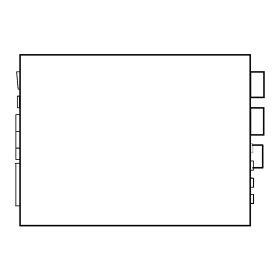
FEHLER! FORMATVORLAGE NICHT DEFINIERT. FEHLER! FORMATVORLAGE NICHT DEFINIERT.FEHLER! FORMATVORLAGE NICHT DEFINIERT. CHAPTER 2 SPECIFICATIONS 2.1 Dimensions Consider the space for the Teach Pendant and MS connectors. Fig. 2.1 HNC-544 Dimensions 2.2 Weight HNC-544 : 12.5 kg... -
Page 6: Power Supply
FEHLER! FORMATVORLAGE NICHT DEFINIERT. FEHLER! FORMATVORLAGE NICHT DEFINIERT.FEHLER! FORMATVORLAGE NICHT DEFINIERT. 2.3 Cooling The controller is cooled by forced air circulation. The locations of the air in- take and exhaust openings are shown are shown in below. Air exhaust fan Air intake fan Fig. - Page 7 FEHLER! FORMATVORLAGE NICHT DEFINIERT. FEHLER! FORMATVORLAGE NICHT DEFINIERT.FEHLER! FORMATVORLAGE NICHT DEFINIERT. 2.6 Specifications Table 2.3 Specifications Item Specifications Applicable robot Cartesian type robot, SCARA type robot, etc. Control axis 1 to 4 axes Control method Numeric control by microprocessor. PTP: Gate motion, Arch motion, Insert motion, Pass mo- Positioning method tion etc.
-
Page 8: Chapter 3 Hardware Composition
FEHLER! FORMATVORLAGE NICHT DEFINIERT. FEHLER! FORMATVORLAGE NICHT DEFINIERT.FEHLER! FORMATVORLAGE NICHT DEFINIERT. CHAPTER 3 Hardware Composition 3.1 Outside Structure ‡ @ ‡ A ‡ B ‡ C ‡ D ‡ E‡ F ‡ G ‡ H Fig.3.1 Front Panel Table 3.1 Parts List Item Memory card port DC24V power fuse holder... - Page 9 FEHLER! FORMATVORLAGE NICHT DEFINIERT. FEHLER! FORMATVORLAGE NICHT DEFINIERT.FEHLER! FORMATVORLAGE NICHT DEFINIERT. ‡ A ‡ B ‡ C ‡ @ ‡ D ‡ E ‡ F ‡ G ‡ H Fig.3.2 Back Panel Table 3.2 Parts List Item DO-1connector DI-1 connector DO-2 connector DI-2 connector Encoder/sensor connector for Z/W-Axis...
-
Page 10: Inside Structure
FEHLER! FORMATVORLAGE NICHT DEFINIERT. FEHLER! FORMATVORLAGE NICHT DEFINIERT.FEHLER! FORMATVORLAGE NICHT DEFINIERT. 3.2 Inside Structure Back side ‡ @ ‡ A ‡ B ‡ C ‡ D Front side Fig.3.3 Inside Structure (Base Plate) Table 3.3 Parts List Item Noise filter Regenerative register Switching regulator (24V) Switching regulator (5V) -
Page 11: Block Composition
FEHLER! FORMATVORLAGE NICHT DEFINIERT. FEHLER! FORMATVORLAGE NICHT DEFINIERT.FEHLER! FORMATVORLAGE NICHT DEFINIERT. 3.3 Block Composition The hardware mainly comprise the following 8 blocks. System control (System board HPC-740A • Controls the entire robot motion. • Stores the position and the system data. •... -
Page 12: Connection Composition
FEHLER! FORMATVORLAGE NICHT DEFINIERT. FEHLER! FORMATVORLAGE NICHT DEFINIERT.FEHLER! FORMATVORLAGE NICHT DEFINIERT. 3.4 Connection Composition HPC-740A HPC-741A M ot or X/Y M em or y car d Syst em boar d Syst em cont r ol M ot or Z/W Axi s cont r ol RS232C Ser vo power boar d Ser vo cont r ol boar d... -
Page 13: Chapter 4 Function
FEHLER! FORMATVORLAGE NICHT DEFINIERT. FEHLER! FORMATVORLAGE NICHT DEFINIERT.FEHLER! FORMATVORLAGE NICHT DEFINIERT. CHAPTER 4 FUNCTION The basic function of the controller is to move the robot to programmed po- sition. To operate the robot easily, the controller has necessary function as following below. -
Page 14: Emergency Stop (E.s.) Function
FEHLER! FORMATVORLAGE NICHT DEFINIERT. FEHLER! FORMATVORLAGE NICHT DEFINIERT.FEHLER! FORMATVORLAGE NICHT DEFINIERT. 4.2 Emergency Stop (E.S.) Function To stop the robot immediately upon occurrence of abnormal status of the robot, the controller is provided with an emergency stop(E.S) function. Emergency stop E.S. - Page 15 FEHLER! FORMATVORLAGE NICHT DEFINIERT. FEHLER! FORMATVORLAGE NICHT DEFINIERT.FEHLER! FORMATVORLAGE NICHT DEFINIERT. Wiring for the E.S. connector Teach Pendant E.S. switch Encoder disconnect detection circuit +24V 10P E.S. connector Fuse External E.S. switch E.S. output (Opens at E.S. output) Internal E.S. circuit Controller inside Controller outside...
-
Page 16: Chapter 6 Hardware Setting
FEHLER! FORMATVORLAGE NICHT DEFINIERT. FEHLER! FORMATVORLAGE NICHT DEFINIERT. CHAPTER 6 Hardware Setting 6.1 DIP Switch (SW2) on HNC System Board There is a DIP switch on the system board (HPC-740A.) Refer to the following table below for the DIP switch function. O FF Fig.6.1 DIP Switch (SW2) Table 6.1 DIP Switch Function... -
Page 17: System Indicator
FEHLER! FORMATVORLAGE NICHT DEFINIERT. FEHLER! FORMATVORLAGE NICHT DEFINIERT. System Indicator An error code will be displayed on the system indicator on system board(HPC-740A) in case of the error . Example : Overrun Indicator will display “E51” repeatedly. The display above is repeated. Table 6.2 Error code ON-LINE Error message... - Page 18 FEHLER! FORMATVORLAGE NICHT DEFINIERT. FEHLER! FORMATVORLAGE NICHT DEFINIERT.
-
Page 19: Pendant Remove Switch
FEHLER! FORMATVORLAGE NICHT DEFINIERT. FEHLER! FORMATVORLAGE NICHT DEFINIERT. 6.3 Pendant Remove Switch The Pendant remove switch is used for connecting or disconnecting while the power is supplied to the controller. This feature allows you to read the error message when any event of error occurrence. Pendant remove switch Fig.6.2 Pendant Remove Switch When disconnecting the Teach Pendant from the controller... -
Page 20: Chapter 7 Preventive Maintenance
FEHLER! FORMATVORLAGE NICHT DEFINIERT. FEHLER! FORMATVORLAGE NICHT DEFINIERT. CHAPTER 7 Preventive Maintenance Confirm that surroundings meet specifications; frequency, dielectric strength, etc. Periodical maintenance is highly recommended for full performance and longer life time. If malfunction happens, follow the “troubleshooting flowchart” in later chapter. 7.1 Dust Filter The controller is cooled by forced air circulation. -
Page 21: Chapter 8 Servo System Adjustment
FEHLER! FORMATVORLAGE NICHT DEFINIERT. FEHLER! FORMATVORLAGE NICHT DEFINIERT. CHAPTER 8 Servo System Adjustment This controller has a servo driver as a peripheral device that needs to be adjusted to function as the robot controller. This chapter describes the ad- justment procedure of the servo driver. The motor rotates with an operation speed command sent from the con- troller and received at the servo driver unit. -
Page 22: Servo Parameter Setting And Adjust- Ment
FEHLER! FORMATVORLAGE NICHT DEFINIERT. FEHLER! FORMATVORLAGE NICHT DEFINIERT. 8.1 Servo Parameter Setting and Adjust- ment All the parameters are preset before shipment at the factory. However, it will be allowed to adjust the servo parameters only if abnormal noise or hunting is occurred. - Page 23 FEHLER! FORMATVORLAGE NICHT DEFINIERT. FEHLER! FORMATVORLAGE NICHT DEFINIERT. Following parameter is displayed in order by pressing the key. DOWN Table 8.1 Parameter List Default Parameter Specification Adjustment value Speed control proportional 00050 Allowed gain 00050 Speed control integral gain Allowed Kvff 00000 Feed forward gain...
- Page 24 FEHLER! FORMATVORLAGE NICHT DEFINIERT. FEHLER! FORMATVORLAGE NICHT DEFINIERT. Pressing the alarm reset switch on the front panel of the con- troller is same as this function.
- Page 25 FEHLER! FORMATVORLAGE NICHT DEFINIERT. FEHLER! FORMATVORLAGE NICHT DEFINIERT. • OFFSET ADJ. This is the command for current feedback offset adjustment on HPC-741A. The current feedback which interface the motor cur- rent to CPU through A/D converter. This command adjust the time lag between softwere setiting 0 and hardware setting 0.
- Page 26 FEHLER! FORMATVORLAGE NICHT DEFINIERT. FEHLER! FORMATVORLAGE NICHT DEFINIERT. 8.1.1 Parameters Kvp, Kvi Increase the value when Speed control propor- overshooting because of tional gain overload. Setting the Default: 50 value excessively may Setting range: 0 to 300 cause an abnormal noise. Adjust properly.
- Page 27 FEHLER! FORMATVORLAGE NICHT DEFINIERT. FEHLER! FORMATVORLAGE NICHT DEFINIERT. Reserved for the system. (Currently not used.) UVW Out Filter (UVW phase PWM filter) Default value Standard value : 0 Setting range : 0 to 100 Effects to PWM output which is in proportion to the deference be- tween the current command value and actural current value.
- Page 28 FEHLER! FORMATVORLAGE NICHT DEFINIERT. FEHLER! FORMATVORLAGE NICHT DEFINIERT. According to H8CPU version up from 1.21 to 1.30 inside of the servo driver, following setting are added. (Use the controller with 2.41 version (and after) P-ROM when using servo driver with H8CPU 1.30 version.) Allows you to replace “OverCur.
- Page 29 FEHLER! FORMATVORLAGE NICHT DEFINIERT. FEHLER! FORMATVORLAGE NICHT DEFINIERT. Expansion 3 Reserved for the system. According to H8CPU version up from 1.21 to 1.30 inside of the servo driver, this parameter is changed from “Expansion 2” to “OverCur. Time.” (Use the controller with 2.41 version (and after) P-ROM when using servo driver with H8CPU 1.30 version.) OverCur.
- Page 30 FEHLER! FORMATVORLAGE NICHT DEFINIERT. FEHLER! FORMATVORLAGE NICHT DEFINIERT. Rotation Dir Default value Standard value Setting range : 0 or 1 Specifies direction for the motor revolution. Rotates reversibly by specifying the value “1.” I/F Mode Default value : VELOCITY Standard value : VELOCITY Setting summary : VELOCITY (Speed command mode) POSITION (Position command mode)
- Page 31 FEHLER! FORMATVORLAGE NICHT DEFINIERT. FEHLER! FORMATVORLAGE NICHT DEFINIERT. Enc. Pulse Default value : 1500 Standard value : 1500ppr Setting range : 1500 or 2500 Displays the encoder pulse count per a motor revolution. The value is fixed and not changeable. According to H8CPU version up from 1.21 to 1.30 inside of the servo driver, this parameter setting is changed.
-
Page 32: Servo Driver Protection
FEHLER! FORMATVORLAGE NICHT DEFINIERT. FEHLER! FORMATVORLAGE NICHT DEFINIERT. 8.2 Servo Driver Protection If an alarm is occurred under the servo driver protection, it is possible to confirm the alarm status (“Err1” at the servo parameter display) with Teach Pendant. Once an abnormal status is detected, E.S. is activated. It intercept the mo- tor power, and the Teach Pendant display the error message and output the servo alarm. -
Page 33: Regenerative Processing
FEHLER! FORMATVORLAGE NICHT DEFINIERT. FEHLER! FORMATVORLAGE NICHT DEFINIERT. Error Meaning Cause and solution Abnormal bus (1)Confirm if the fuse break or not control line (2)Confirm the power is supplied to the HPC- Bus Uncon- (Bus connection 741A. nect error between (3)Confirm the connection for the H8/534 CPU CPU and servo) on the HPC-741A, and P-ROM. -
Page 34: Chapter 9 Trouble Shooting
FEHLER! FORMATVORLAGE NICHT DEFINIERT. FEHLER! FORMATVORLAGE NICHT DEFINIERT. CHAPTER 9 Trouble Shooting 9.1 Error Message An error message is displayed to the Teach Pendant. Also the error is expressed by the error code on the Teach Pendant during the operation. Refer to separated volume “OPERATION MANUAL”... -
Page 35: Positioning Error
FEHLER! FORMATVORLAGE NICHT DEFINIERT. FEHLER! FORMATVORLAGE NICHT DEFINIERT. 9.2.1 Positioning Error E I s the designated address from the PLC correct? Does i t m i sposi t i on E I s teaching is correct? speci f i c posi t i on? E I s the system board defective? E I s PCA confirmed? Does it misposition to the... -
Page 36: Main Flowchart
FEHLER! FORMATVORLAGE NICHT DEFINIERT. FEHLER! FORMATVORLAGE NICHT DEFINIERT. 9.2.2 Main Flowchart Main flowchart Is the power lamp on the Check the AC power supply.(Go to ST1) front panel lit? inside controller working? Check the AC power supply. Is the external emergency stop or the E.S on the Teach Pendant OFF? Release the E.S. -
Page 37: Ac Power Check
FEHLER! FORMATVORLAGE NICHT DEFINIERT. FEHLER! FORMATVORLAGE NICHT DEFINIERT. 9.2.3 AC Power Check AC power check Is the AC plug connected firmly? Connect the AC plug firmly. E P ower switch is broken? Turn the power switch ON. Is the fan inside of the Check the AC power. -
Page 38: Dc Supply Check
FEHLER! FORMATVORLAGE NICHT DEFINIERT. FEHLER! FORMATVORLAGE NICHT DEFINIERT. 9.2.4 DC Supply Check DC supply check Replace the fuse. Is the +24V LED on the system board HPC-767 lit? (D9) 24V(3A) fuse is broken? Contact your distributor. Connect it. Is the +5V LED on the system Is the switching regulator output(PS1) board HPC-767 lit? (D5) inside of the controller working... -
Page 39: Display Check
FEHLER! FORMATVORLAGE NICHT DEFINIERT. FEHLER! FORMATVORLAGE NICHT DEFINIERT. 9.2.5 Display Check Display check Connect them. Is the display totally blank? Are the connectors for the Teach Pendant connected firmly? Is the display normal when The drive circuit inside of the replacing the other Teach controller may be defective. -
Page 40: A-Cal Mode Check
FEHLER! FORMATVORLAGE NICHT DEFINIERT. FEHLER! FORMATVORLAGE NICHT DEFINIERT. 9.2.6 A-CAL Mode Check A-CAL mode check Are the connectors for the Connect them. robot on the back panel connected firmly? Is the external E.S working? Release it. Is the interlock or STOP Release it. -
Page 41: Key-In Mode Check
FEHLER! FORMATVORLAGE NICHT DEFINIERT. FEHLER! FORMATVORLAGE NICHT DEFINIERT. 9.2.7 KEY-IN Mode Check KEY-I N m ode check I s t her e any m i st ake f or t he oper at i on? i R ef er t o t he Cor r ect t he m i st ake, and t r y agai n. -
Page 42: Teach Mode Check
FEHLER! FORMATVORLAGE NICHT DEFINIERT. FEHLER! FORMATVORLAGE NICHT DEFINIERT. 9.2.8 TEACH Mode Check c T he robot does not move. TEACH mode check The connector for the robot on Connect them. the back panel is connected firmly? Is the STOP signal(IN5 of DI signal) working? Release the STOP signal. -
Page 43: Check Mode Check
FEHLER! FORMATVORLAGE NICHT DEFINIERT. FEHLER! FORMATVORLAGE NICHT DEFINIERT. 9.2.9 CHECK Mode Check CHECK mode check c T he robot does not move. Is the STOP signal(IN5 of DI Release it. signal) working? Does robot start Refer to ST6 “ KEY-IN mode check ” . positioning while pressing the START switch,? Does it stop positioning when... - Page 44 FEHLER! FORMATVORLAGE NICHT DEFINIERT. FEHLER! FORMATVORLAGE NICHT DEFINIERT. 9.2.10 AUTO Mode Check AUTO mode check c T he robot does not perform the positioning. Are the connectors for the Connect them. robot back panel connected firmly? Is the programming of the external devices correct? Reprogram it.
-
Page 45: Appendix A Check Pin And Indicators
APPENDIX APPENDIX APPENDIX A Check Pin and Indicators APPENDIX A.1 System Board•HPC-740A• ‚v ² ‚y ² ‚x ² ‚w ² J000 Axis Axis Axis Axis H8/534 H8/534 H8/534 H8/534 J001 J002 J440 IN0-IN3 J940 IN4-IN7 J040 IN8-IN11 IN12-IN1 J981 J070 RAM RAM ROM ROM J291... - Page 46 APPENDIX 2) WDT LED is lit when the error is detected. 3) Parallel input monitor is lit when input is ON.
- Page 47 APPENDIX A-Axis Z-Axis B-Axis W-Axis ‚v ² ‚y ² ‚x ² ‚w ² J000 H8/534 H8/534 H8/534 H8/534 J001 J002 J440 J940 J040 IN15 J981 J070 RAM RAM ROM ROM J291 EVEN ODD Fig.A.2 System Board•HPC-740A• Table A.2 Function for the Indicators Parts Function Parts...
- Page 48 APPENDIX APPENDIX A.2 Servo Driver Power Board (HPC- 741A• IGBT IGBT IGBT ‚i‚T ‚i‚V ‚i‚U C162 C163 C164 D134 IGBT Fig.A.3 Servo Driver Power Board (HPC-741A• Table A.3 Function for the Indicators Parts Function Parts Function 1 XW0V (CH17) XW0V power monitor 2 XZ0V (CH18) XZ0V power monitor 3 A0V (CH19) A0V power monitor...
-
Page 49: Appendix B Spare Parts List
APPENDIX APPENDIX B Spare Parts List Fig.A.4 Spare Parts List Item Part No. Maker Lithium battery H-3339 HIRATA CPU board HPC-740A HIRATA Power board HPC-741A HIRATA...
Need help?
Do you have a question about the HNC-544 and is the answer not in the manual?
Questions and answers