Advertisement
National Comfort Products
539 Dunksferry Road • Bensalem, PA 19020
(215) 244-1400 • 1-800-523-7138 • Fax: (215) 244-9579
R410a
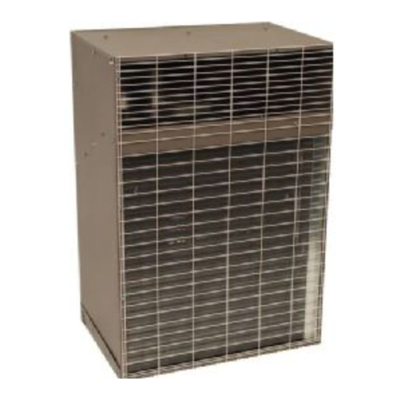
SPLIT-SYSTEM CONDENSING UNIT INSTALLATION INSTRUCTIONS
Before Installing Unit
1.
Check all local codes and ordinances that could affect in-
stallation. The manufacturer assumes no responsibility for
equipment installed in violation of any code requirements.
2.
Be sure that the electrical data specified on the unit rating
plate corresponds to what is available at the installation site
and NEC for installation requirements.
3.
Be sure that the electrical service provided to the building
can handle the load imposed by the unit.
4.
This unit should be installed in an outside wall for thru-the-
wall installation ONLY.
5.
NCP condensing units may only be used with indoor evapo-
rator coils utilizing an expansion (TXV) valve. Self-equaliz-
ing components are required to reduce compressor starting
problems. If self-equalizing components are not used, field
installed hard start kits will be required.
Hard start kits must be compatible with Bristol compres-
sors.
Start Cap for Various Sizes
18,000 BTU
24,000 BTU
30,000 BTU
Start relays to be sized to µFd of capacitor used.
6.
The unit must be installed with the top level front to rear
left to right.
Step 1 - Thru-the-Wall Installation
In thru-the-wall installation, due to the various types of wall con-
struction, it is not possible to provide detailed instructions. The
following is a list of general requirements and cautions for in-
stalling these units.
1.
Masonry walls must have a lintel to support the wall.
2.
Extend the unit approximately 3/4" beyond outside surface
of the wall. Optional mounting angles can be purchased
from the factory or field fabricated for locating and mounting
the unit in the wall.
3.
The wall opening across the top and bottom must be
flashed. Bottom flashing to cover the full foot print of unit
and extend up 2'' on 3 sides. All openings around the top,
sides and bottom must be caulked and sealed. Care must
be taken not to plug the openings in the front of the base
pan of the unit.
THE UNIT MUST NEVER BE PLACED ON ITS SIDE OR UPSIDE DOWN AS THE COMPRESSOR OIL WILL RUN IN THE COOLING
CIRCUIT AND SERIOUSLY DAMAGE THE UNIT. BASE PAN MUST ALWAYS BE ON THE BOTTOM OF THE INSTALL.
PLEASE NOTE: ALL 2.5 TON UNITS (430 MODELS)
HAVE BEEN DISCONTINUED.
If the optional wall sleeve is used, caulk the spaces between the
sleeve and the wall. Completely fill the clearance between the
unit and the wall sleeve with a polyurethane foam sealant (Fol-
low manufacturer's suggested application manual).
4.
During periods of rain and wind the primary drainage path
may not be adequate to handle the load. Secondary pre-
cautions may also be required but not limited to the follow-
ing:
a. Seal flashing to unit
b. Floor drain
c. Additional field sealing of sheet metal joints
d. Sealing of unused access opening
5.
Clearances to air inlets and outlets must be adequate to en-
sure no air flow obstructions or recirculation of condenser
air flow.
6.
Some architectural designs of buildings will require the unit
to be mounted behind a decorative grille. The performance
(capacity and efficiency) of the unit may be reduced with
the use of these decorative grilles.
The less resistive these grilles are to air flow, the better the units
performance will be.
µFd/Volts
145-175/330
Outdoor louvers provided by others must be approved by NCP
145-175/330
to maintain unit performance and warranty. Care must be taken
145-175/330
to locate coil intake side of unit away from loose debris that may
clog intake.
7.
If the unit is mounted behind a decorative grille, one or both
and
of the following items must be done to eliminate recircula-
tion of air to the unit:
a. The front of the unit must be mounted tight to the inside
b. A barrier must be provided to prevent recirculation of air
8.
The unit
eas where there is no fresh outside air circulation. Cool
fresh outside air must be provided for best unit operation.
Thru-the-wall units may not be located where hot exhausts
from clothes dryer vents, kitchen vents, steam vents or cor-
rosive fumes could come in contact with coil side of unit.
9.
30" clearance is required for service accessibility on the in-
side. If more than one unit is to be installed in the same
area a min. of 48'' vertical must be maintained between
units to minimize recirculation of condenser exhaust air.
1000 3000 4000 SERIES
of the architectural grille
to the unit (mixing of inlet and outlet air) when the front
of the unit is mounted back from the inside of the arch-
tectural grille
must not be mounted in dead-end hallways or ar-
14299706 09/10
1
Advertisement
Table of Contents

Related Manuals for National Comfort Products NCPC-418-1010


Summary of Contents for National Comfort Products NCPC-418-1010
- Page 1 National Comfort Products PLEASE NOTE: ALL 2.5 TON UNITS (430 MODELS) 539 Dunksferry Road • Bensalem, PA 19020 HAVE BEEN DISCONTINUED. (215) 244-1400 • 1-800-523-7138 • Fax: (215) 244-9579 R410a 1000 3000 4000 SERIES SPLIT-SYSTEM CONDENSING UNIT INSTALLATION INSTRUCTIONS If the optional wall sleeve is used, caulk the spaces between the Before Installing Unit sleeve and the wall.
-
Page 2: Step 3 - Leak Checking
d. Carefully remove the rubber plugs from the evaporator Step 2 - Installing Refrigerant Lines liquid and vapor connections. Use caution as the evaporator is pressurized. Important: The outdoor unit is fully charged at the factory for the recom- e. Braze the liquid line to the evaporator liquid connection mended model of indoor unit. -
Page 3: Field Installation
Figure 1 - Installing Refrigerant Lines Field Installation: Install the outdoor and indoor units per the manufacturer’s recommendations. Route the copper lines between the units. Step 1: Step 3: Step 5: The tubing should be cut Flux the copper tube and in- This is not a back seating square. -
Page 4: Step 5 - Refrigerant Charging
When the correct refrigerant charge level is obtained, re- Step 4 - Evacuation move the manifold gauge set. Connect the vacuum pump to the service ports of the liquid Replace the gauge port caps. line and the vapor line service valves. If the vacuum pump lines do not contain shut-off valves, hook up the vacuum Permanently stamp the unit data plate with the total amount of pump through a manifold gauge set, as the vacuum pump... -
Page 5: Step 7 - Maintenance
Sequence of Operations Step 7 - Maintenance for Madison Avenue Option Annually clean the inside of the unit to keep the weep holes in the base pan and in the fan scrolls open to assure proper The compressor crankcase heater will be energized as long as drainage of water from the unit. - Page 6 Figure 2 - Wiring Schematic NCPC ...
- Page 7 Figure 3 - Wiring Schematic Madison Series ...
- Page 8 0.25 0.25 1140 1140 1140 Amps (Full Load) COIL 3.46 3.46 3.46 Face Area DIMENSIONAL DRAWING NCPC-418-1010, NCPC-424-1010, NCPC-430-1010 & MADISON 18 1/2" 2 3/32" 2" 15/16" 1 17/32" 1 17/32" 15/16" 1000 SERIES 2 19/32" 28 21/32" 1 3/8" (2) 7/8"...
- Page 9 SPECIFICATIONS CHART - 3000 SERIES MODEL NO. NCPC-418 NCPC-424 NCPC-430 DIMENSIONS Service Clearance..30” 23 3/4” 23 3/4” 23 3/4” Width Height 32” 32” 32” 18 1/2” 18 1/2” 18 1/2” Length 3/8” 3/8” 3/8” Liquid Valve 3/4” 3/4” 3/4” Vapor Valve NOMINAL CAPACITY B/HR 18,000...
- Page 10 SPECIFICATIONS CHART - 4000 SERIES MODEL NO. NCPC-418 NCPC-424 NCPC-430 DIMENSIONS Service Clearance..30” 29 1/2” 29 1/2” 29 1/2” Width Height 23” 23” 23” 18 1/2” 18 1/2” 18 1/2” Length 3/8” 3/8” 3/8” Liquid Valve 3/4” 3/4” 3/4” Vapor Valve NOMINAL CAPACITY B/HR 18,000...
-
Page 11: Replacement Parts Guide
National Comfort Products 539 Dunksferry Road • Bensalem, PA 19020 • (215) 244-1400 • 1-800-523-7138 • Fax: (215) 244-9579 REPLACEMENT PARTS GUIDE NCPC SERIES 1000 MADISON SERIES 1000 NCPC-418-1010, NCPC-424-1010, NCPC-430-1010 ** MADISON SERIES ONLY ITEM DESCRIPTION NCPC-418 NCPC-424 NCPC-430... - Page 12 National Comfort Products 539 Dunksferry Road • Bensalem, PA 19020 • (215) 244-1400 • 1-800-523-7138 • Fax: (215) 244-9579 REPLACEMENT PARTS GUIDE NCPC SERIES 3000 MADISON SERIES 3000 NCPC-418-3010, NCPC-424-3010, NCPC-430-3010 ** MADISON SERIES ONLY ITEM DESCRIPTION NCPC-418 NCPC-424 NCPC-430...
- Page 13 National Comfort Products 539 Dunksferry Road • Bensalem, PA 19020 • (215) 244-1400 • 1-800-523-7138 • Fax: (215) 244-9579 REPLACEMENT PARTS GUIDE NCPC SERIES 4000 MADISON SERIES 4000 NCPC-418-4010, NCPC-424-4010, NCPC-430-4010 ** MADISON SERIES ONLY ITEM DESCRIPTION NCPC-418 NCPC-424 NCPC-430...
- Page 14 (B) provide a replacement unit. National Comfort Products will not be responsible for: local transportation, removing, related service, labor, diagnosis calls, refrigerant, costs incurred for returning defective parts, damage or repairs required due to faulty installation or improper application by others, damage as a result of fire, wind, floods, lightning, accidents, or corrosive atmosphere.
- Page 15 PROCEDURE FOR WARRANTY FAILURE National Comfort Products are warranted for one year after the date of installation, or one year from the date of manufacture. The compressor carries an extended 5 year warranty after the date of installation. Use the following procedure for returning parts for warranty replacement.
-
Page 16: Engineering Specification Guide
National Comfort Products 539 Dunksferry Road • Bensalem, PA 19020 • (215) 244-1400 • 1-800-523-7138 • Fax: (215) 244-9579 ENGINEERING SPECIFICATION GUIDE THRU-THE-WALL SPLIT SYSTEM CONDENSING UNIT SAFETY APPROVAL - Each unit shall be ETL listed for safety approval. GENERAL - Each outdoor condensing unit shall be factory assembled and run tested. - Page 20 PLEASE NOTE: ALL 2.5 TON UNITS (430 MODELS) HAVE BEEN DISCONTINUED. R-410a Split-System Condensing Unit Installation Instructions - Rev 09/10...
Need help?
Do you have a question about the NCPC-418-1010 and is the answer not in the manual?
Questions and answers