Table of Contents
Advertisement
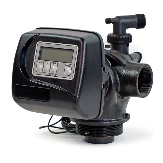
Water Specialist
1.5", 2" and 2"QC Control Valve
Drawings and Service Manual
HYDROCARBONS SUCH AS KEROSENE, BENZENE, GASOLINE, ETC., MAY DAMAGE
PRODUCTS THAT CONTAIN O-RINGS OR PLASTIC COMPONENTS. EXPOSURE TO
SUCH HYDROCARBONS MAY CAUSE THE PRODUCTS TO LEAK. DO NOT USE THE
PRODUCT(S) CONTAINED IN THIS DOCUMENT ON WATER SUPPLIES THAT CONTAIN
HYDROCARBONS SUCH AS KEROSENE, BENZENE, GASOLINE, ETC.
Advertisement
Table of Contents

Related Manuals for Clack Valves WS1.5

Summary of Contents for Clack Valves WS1.5
- Page 1 Water Specialist 1.5”, 2” and 2”QC Control Valve Drawings and Service Manual HYDROCARBONS SUCH AS KEROSENE, BENZENE, GASOLINE, ETC., MAY DAMAGE PRODUCTS THAT CONTAIN O-RINGS OR PLASTIC COMPONENTS. EXPOSURE TO SUCH HYDROCARBONS MAY CAUSE THE PRODUCTS TO LEAK. DO NOT USE THE PRODUCT(S) CONTAINED IN THIS DOCUMENT ON WATER SUPPLIES THAT CONTAIN HYDROCARBONS SUCH AS KEROSENE, BENZENE, GASOLINE, ETC.
-
Page 2: Ws1.5", 2" And 2"Qc Drawings And Service Manual
Page 2 WS1.5", 2" and 2"QC Drawings and Service Manual... -
Page 3: Table Of Contents
WS1.5", 2" and 2"QC Drawings and Service Manual Page 3 Table of Contents Pages Installation Summary General Specifi cations and Pre-Installation Checklist Valve Port Orientation Diagrams Installation Instructions 9-10 System Startup Troubleshooting Procedures 17-20 WS1.5 Control Valve Cycle Positions 21-23... -
Page 4: Installation Summary
Page 4 WS1.5", 2" and 2"QC Drawings and Service Manual Installation Summary Installation Date: ___________________________________________ Installation Location: _______________________________________ Installer(s): _______________________________________________ Phone Number: ____________________________________________ Application Type: (Softener) _______ Other: ____________________ Water Source: ____________________________________________ Water Test Results: Hardness: ___________ Iron: ___________pH:___________________ Other: ___________________________________________________... -
Page 5: General Specifi Cations And Pre-Installation Checklist
WS1.5", 2" and 2"QC Drawings and Service Manual Page 5 Table 1 General Specifi cations and Pre-Installation Checklist Minimum/Maximum Operating Pressures 20 psi (138 kPa) -125 psi (862 kPa) Minimum/Maximum Operating Temperatures 40°F (4°C) - 110°F (43°C) Power Adapter: Supply Voltage... -
Page 6: Valve Port Orientation Diagrams
Page 6 WS1.5", 2" and 2"QC Drawings and Service Manual WS1.5 Gen 2... - Page 7 WS1.5", 2" and 2"QC Drawings and Service Manual Page 7...
- Page 8 Page 8 WS1.5", 2" and 2"QC Drawings and Service Manual WS2 QC...
-
Page 9: Installation Instructions
GENERAL INSTALLATION & SERVICE WARNINGS Distributor Tube Pipe Height The control valve and fi ttings are not designed to support the for Top Mount WS1.5, WS2 and and WS2 QC control valves weight of the system or the plumbing. Control Valves WS1.5... - Page 10 Page 10 WS1.5", 2" and 2"QC Drawings and Service Manual 7. Regenerant tanks should be accessible for easy refi lling. If the control valve is to be used to regenerate the water conditioner with brine (saturated salt solution) or other regenerants, use a polyethylene tube to connect the brine valve contained in the regenerant tank to the regenerant port on the control valve.
-
Page 11: System Startup
WS1.5", 2" and 2"QC Drawings and Service Manual Page 11 System Startup 1. After installation is completed, turn on the supply water to check for leaks 2. Fully open a cold water faucet downstream of the system 3. Allow water to run until clear 4. -
Page 12: Front Cover And Drive Assembly
Page 12 WS1.5", 2" and 2"QC Drawings and Service Manual Service Instructions 1) Drive Assembly Disassembly and Inspection: Remove the valve cover to access the drive assembly. The drive bracket must be removed to access the drive cap assembly and pistons or the drive gear cover. It is not necessary to remove the PC board from the drive bracket to remove the drive bracket. - Page 13 WS1.5", 2" and 2"QC Drawings and Service Manual Page 13 Replace the motor if necessary. Do not lubricate the motor or the gears. To reinstall the motor, move the spring clip loop to the right and hold. Gently turn the motor while inserting so that the gear on the motor meshes with the gears under the drive gear cover.
- Page 14 Page 14 WS1.5", 2" and 2"QC Drawings and Service Manual 3) Main Piston and Regenerant Piston Disassembly and Inspection Attached to the drive cap assembly is the main piston and depending on the confi guration, a regenerant piston. The regenerant piston (the small diameter one behind the main piston) is removed from the main piston by unsnapping it from its disassembly latch.
-
Page 15: Injector Cap, Screen, Injector Plug And Injector 31-33
Disassembly and Inspection To clean or replace the refi ll fl ow control, remove the nut (WS2) or pull out the locking clip (WS1.5 valves) and then pull the fi tting straight out. Remove the fl ow control retainer. The fl ow control can be removed by prying upward through the side slots of the retainer with a small blade fl... - Page 16 Page 16 WS1.5", 2" and 2"QC Drawings and Service Manual 8) Drain Line Flow Control Disassembly and Inspection Depending on the fl ow control installed on the unit, remove the red plastic retaining clip (plastic fl ow control) or the (4) screws (stainless steel fl...
-
Page 17: Troubleshooting Procedures
WS1.5", 2" and 2"QC Drawings and Service Manual Page 17 Table 3 Troubleshooting Procedures Problem Possible Cause Solution a. No power at electric outlet a. Repair outlet or use working outlet b. Control valve Power Adapter not plugged into b. Plug Power Adapter into outlet or connect... - Page 18 Page 18 WS1.5", 2" and 2"QC Drawings and Service Manual Problem Possible Cause Solution a. Bypass valve is open or faulty a. Fully close bypass valve or replace b. Media is exhausted due to high water usage b. Check program settings or diagnostics for abnormal water usage c.
- Page 19 WS1.5", 2" and 2"QC Drawings and Service Manual Page 19 Problem Possible Cause Solution a. Motor not inserted full to engage pinion, motor a. Disconnect power, make sure motor is wires broken or disconnected fully engaged, check for broken wires,...
- Page 20 Page 20 WS1.5", 2" and 2"QC Drawings and Service Manual Problem Possible Cause Solution a. Control valve programmed for ALT A or b, a. Press NEXT and REGEN buttons for 3 nHbP, SEPS, or AUX MAV with out having a...
-
Page 21: Ws1.5 Control Valve Cycle Positions
WS1.5", 2" and 2"QC Drawings and Service Manual Page 21 WS1.5 Control Valve Cycle Positions SERVICE Raw water inlet Treated water supply BACKWASH Raw water inlet Backwash water to drain Raw/hard water is bypassed during regeneraion... - Page 22 Page 22 WS1.5", 2" and 2"QC Drawings and Service Manual DRAW Raw water inlet Regenerant water to drain Raw/hard water is bypassed during regeneraion Regenerant solution being drawn in Injector feed from raw water inlet RINSE Rinse water to drain...
-
Page 23: Ws2 Control Valve Cycle Positions
WS1.5", 2" and 2"QC Drawings and Service Manual Page 23 TREATED WATER REFILL Raw water inlet Treated water supply Treated water to regenerant tank WS2 Control Valve Cycle Positions SERVICE Raw water inlet Treated water supply... - Page 24 Page 24 WS1.5", 2" and 2"QC Drawings and Service Manual BACKWASH Backwash water to drain Raw water inlet Raw/hard water is bypassed during regeneraion DRAW Raw water inlet Regenerant water to drain Raw/hard water is bypassed during regeneraion Regenerant solution...
- Page 25 WS1.5", 2" and 2"QC Drawings and Service Manual Page 25 RINSE Rinse water to drain Raw water inlet Rinse water is bypassed during rinse cycle TREATED WATER REFILL Raw water inlet Treated water supply Treated water to regenerant tank...
-
Page 26: Description
Page 26 WS1.5", 2" and 2"QC Drawings and Service Manual WS1.5 Gen 1 Drive Cap Assembly, Downfl ow Piston, Regenerant Piston, Spacer Stack Assembly and Main Body Drawing No. Order No. Description Quantity V3004 WS1 Drive Cap Assembly V3135 O-ring 228 V3407 WS1.25/1.5 Piston Downfl... - Page 27 WS1.5", 2" and 2"QC Drawings and Service Manual Page 27 WS1.5 GEN 2 Drive Cap Assembly, Downfl ow Piston, Regenerant Piston, Spacer Stack Assembly and Main Body Drawing No. Order No. Description Quantity V3004 WS1 Drive Cap Assembly V3135 O-ring 228 V3407 WS1.25/1.5 Piston Downfl...
- Page 28 Page 28 WS1.5", 2" and 2"QC Drawings and Service Manual WS2 Drive Cap Assembly, Downfl ow Piston, Regenerant Piston, Spacer Stack Assembly and Main Body Drawing No. Order No. Description Quantity V3726* WS2 BRINE PISTON ASSEMBLY V3725 WS2 PISTON DOWNFLOW ASSEMBLY...
-
Page 29: Spacer Stack Assembly
WS1.5", 2" and 2"QC Drawings and Service Manual Page 29 WS2 Quick Connect Drive Cap Assembly, Downfl ow Piston, Regenerant Piston, Spacer Stack Assembly and Main Body Drawing No. Order No. Description Quantity V3726** WS2 BRINE PISTON ASSEMBLY V3725 WS2 PISTON DOWNFLOW ASSEMBLY... -
Page 30: Base Assemblies
Page 30 WS1.5", 2" and 2"QC Drawings and Service Manual V3064 WS2H/2L 4 INCH BASE ASY Drawing No. Order No. Description Quantity V3202-01 WS2H BASE V3419 O-RING 347 V3055 WS2H/2L FLANGE BASE ASY Drawing No. Order No. Description Quantity V3444... - Page 31 WS1.5", 2" and 2"QC Drawings and Service Manual Page 31 WS1.5 Regenerant Components Drawing No. Order No. Description Quantity V3422 Bolt, 1/4-20 x 1 Stainless Steel V3403 Injector Cap V3417 O-ring -220 V3404 Injector Screen See page 33 WS 1.5 Injector...
- Page 32 Page 32 WS1.5", 2" and 2"QC Drawings and Service Manual WS2 Injector Valve Body, Refi ll Flow Control and Injector Drawing No. Order No. Description Quantity V3477 WS2H INJECTOR CAP V3152 O-RING 135 V3727 WS2 INJECTOR BODY ASSEMBLY See page 33...
- Page 33 V301015B through V3010-15H injectors include one V3416 o-ring 012 (lower) and one V3171 o-ring 013 (upper). For WS1 and V3010-15I injector includes two V3171 o-ring 013 and is for use on WS1.5 Gen 2 valves only. WS1.25 valves. Do not use on *Requires a V3158-02 WS1 DRN ELBOW ¾...
- Page 34 Page 34 WS1.5", 2" and 2"QC Drawings and Service Manual WS1.5 GEN 1 Refi ll Flow Control Assembly and Refi ll Port Plug Drawing No. Order No. Description Quantity V3195-01 WS1 Refi ll Port Plug Assembly V3415 WS1.5 BLFC Adapter...
-
Page 35: Injector Graphs
WS1.5", 2" and 2"QC Drawings and Service Manual Page 35 VIOLET, ORDER NO. V3010-15B VIOLET, ORDER NO. V3010-15B or V3010-2R-15B or V3010-2R-15B Metric Units US Units Total Total Slow Rinse Slow Rinse Draw Draw Pressure (kPa) Pressure (psi) RED, ORDER NO. V3010-15C RED, ORDER NO. - Page 36 Page 36 WS1.5", 2" and 2"QC Drawings and Service Manual WHITE, ORDER NO. V3010-15D WHITE, ORDER NO. V3010-15D or V3010-2T-15D or V3010-2T-15D Metric Units US Units Total Total Slow Rinse Slow Rinse Draw Draw Pressure (kPa) Pressure (psi) BLUE, ORDER NO. V3010-15E BLUE, ORDER NO.
- Page 37 WS1.5", 2" and 2"QC Drawings and Service Manual Page 37 GREEN, ORDER NO. V3010-15G GREEN, ORDER NO. V3010-15G Metric Units US Units Total Total Slow Rinse Slow Rinse Draw Draw Pressure (psi) Pressure (kPa) ORANGE, ORDER NO. V3010-15H ORANGE, ORDER NO. V3010-15H...
- Page 38 Page 38 WS1.5", 2" and 2"QC Drawings and Service Manual Order No. V3010-2A Order No. V3010-2B US Units US Units Total Total Slow Rinse Slow Rinse Draw Draw Pressure (psi) Pressure (psi) Order No. V3010-2D Order No. V3010-2C US Units...
- Page 39 WS1.5", 2" and 2"QC Drawings and Service Manual Page 39 Order No. V3010-2A Order No. V3010-2B Metric Units Metric Units Total Total Slow Rinse Slow Rinse Draw Draw Pressure (kPa) Pressure (kPa) Order No. V3010-2C Order No. V3010-2D Metric Units...
-
Page 40: Drain Line Flow Control (Dlfc)
Page 40 WS1.5", 2" and 2"QC Drawings and Service Manual Drain Line Flow Controls All drain line fl ow control housings are shipped without fl ow control washers. See drain line fl ow control washer section for available fl ow selections. - Page 41 WS1.5", 2" and 2"QC Drawings and Service Manual Page 41 Drain Line Flow Control Washers Order No. Description V3162-XXX V3162-xx V3162-007 .7 GPMDrain line fl ow control Flow Rate Identification V3162-010 1.0 GPMDrain line fl ow control 5/8" V3162-013 1.3 GPMDrain line fl ow control V3162-017 1.7 GPMDrain line fl...
-
Page 42: Water Meter (Not Shown Below) 42
7. Re-install the meter retaining clip V3632 as shown below (or the U-shaped V3223 WS2 Meter Clip). 8. Open the bypass for the system slowly to bring back into service and check to be sure you have no water leaks. The V3118-03 has a groove to line up with the V3501 WS1.5/2 Turbine Clip. Bend clip after install Typical meter retaining clip installation. -
Page 43: Motorized Alternating Valve Applications
WS1.5", 2" and 2"QC Drawings and Service Manual Page 43 Motorized Alternating Valve Piston Style Applications For V3071, V3071BSPT, V3076 or V3076BSPT OPERATING PRESSURES: 20 PSI MINIMUM / 125 PSI MAXIMUM OPERATING TEMPERATURES: 40°F MINIMUM / 110°F MAXIMUM Service or Installation of Motor: Do not lubricate the motor or the gears. To install the motor, move the spring clip loop to the right and hold. - Page 44 Page 44 WS1.5", 2" and 2"QC Drawings and Service Manual Twin Tank Alternator: If the control valve manual does not include instructions for setting up ALTA and ALTb software, please contact your local equipment supplier for current copies of installation instructions. If the control valve is in an error state during regeneration mode, the MAV will close the B port and keep open the A port until the error is corrected and reset.
- Page 45 WS1.5", 2" and 2"QC Drawings and Service Manual Page 45 1.5” Piston Style MAV's (See Installation Instructions on Motorized Alternating Valves) Order No. V3071 • Description: MOTOR ALT VLV 1.5 NPT REV2 or Order No. V3071BSPT • Description: MOTOR ALT VLV 1.5 BSPT REV2 Quantity Drawing No.
- Page 46 Page 46 WS1.5", 2" and 2"QC Drawings and Service Manual 2” Piston Style MAV's (See Installation Instructions on Motorized Alternating Valves) Order No. V3076 • Description: MOTOR ALT VLV 2 NPT REV2 or Order No. V3076BSPT • Description: MOTOR ALT VLV 2 BSPT REV2 Quantity Drawing No.
- Page 47 WS1.5", 2" and 2"QC Drawings and Service Manual Page 47...
-
Page 48: No Hard Water Bypass
Page 48 WS1.5", 2" and 2"QC Drawings and Service Manual Order No. V3097 • Description: NO HARDWATERBYPASS 15INMXF NPT or Order No. V3097BSPT • Description: NOHARDWATERBYPASS 15INMXF BSPT Quantity Drawing No. Order No. Description V3097 V3097BSPT V3073 MAV/NOHWBY COVER ASY... - Page 49 WS1.5", 2" and 2"QC Drawings and Service Manual Page 49 Order No. V3098 • Description: NO HARDWATERBYPASS 2INMXF NPT or Order No. V3098BSPT • Description: NO HARDWATERBYPASS 2INMXF BSPT Quantity Drawing No. Order No. Description V3098 V3098BSPT V3073 MAV/NOHWBY COVER ASY...
- Page 50 Page 50 WS1.5", 2" and 2"QC Drawings and Service Manual...
- Page 51 Changes to WS 2” and 2” QC Injectors table. ** V3010-2X-15X Injectors contain a V3010-2-15 WS2 injector adapter with a WS1.5 injector inside V3010-2X injectors and the V3010-2-15 Adapter include a V3283 O-RING 117 and a V3284 O-RING 114. The V3010-2-15 Adapter allows the 2"...
- Page 52 Page 52 WS1.5", 2" and 2"QC Drawings and Service Manual CLACK CORPORATION FIVE-YEAR SOFTENER AND FILTER CONTROLS LIMITED WAR RAN TY Clack Corporation (”Clack”) warrants to OEM that its Softener and Filter Control Valves will be free from defects in material and work man ship under normal use and service for a period of fi...
Need help?
Do you have a question about the WS1.5 and is the answer not in the manual?
Questions and answers