
Subscribe to Our Youtube Channel
Related Manuals for Agromehanika AGT 860

Summary of Contents for Agromehanika AGT 860
- Page 1 AGT 850 AGT 860 INSTRUCTIONS FOR USE AGROMEHANIKA reserves the right to changes in design or modification of the product without any liability towards informing the customer before and after each change.
-
Page 3: Table Of Contents
INDEX EC DECLARATION OF CONFORMITY................2 GENERAL ........................3 SAFETY ........................4 SAFETY SIGNS ..............................4 DEFINITIONS ................................. 4 SAFETY WARNINGS ............................5 USER OR CUSTOMER ............................6 2.4.1 PREPAREDNESS FOR DANGERS ....................... 7 2.4.2 PERSONAL PROTECTION ........................... 7 SAFETY INSTRUCTIONS BEFORE USING THE TRACTOR ............... 8 2.5.1 ENTERING THE TRACTOR ......................... - Page 4 TECHNICAL SPECIFICATION .................. 26 MANUFACTURER'S INFORMATION ......................26 REPLACEMENT PARTS ............................ 27 GENERAL DESCRIPTION OF TRACTOR ..............28 DESCRIPTION OF TRACTOR'S MAIN COMPONENTS ................29 DESCRIPTION OF MAIN SAFETY COMPONENTS ..................31 4.2.1 CABIN ................................31 4.2.2 ROLL BAR ..............................34 4.2.3 SAFETY BELT .............................
- Page 5 4.10 ELECTRICAL SYSTEM..........................82 4.10.1 BATTERY ..............................82 4.10.2 ELECTRIC STARTER ..........................83 4.10.3 ALTERNATOR ............................83 4.10.4 FUSES ............................... 83 4.10.5 SOCKET FOR CONNECTIONS (ISO 1724) ..................84 TRACTOR TRANSPORT ................... 85 LOADING ................................85 UNLOADING ................................ 86 TOWING ................................86 TRACTOR SETTINGS ....................
- Page 6 IMPLEMENT ..............................108 7.7.1 CONNECTION AND DISCONNECTION OF IMPLEMENT ON REAR HYDRAULIC LIFT MECHANISM ............................... 108 7.7.2 CONNECTION AND DISCONNECTION OF IMPLEMENT ON FRONT HYDRAULIC LIFT MECHANISM ............................... 111 7.7.3 CONNECTION AND DISCONNECTION OF IMPLEMENT ON REAR TOWING HOOK ....112 CARDAN SHAFT (NOT DELIVERED) ......................
- Page 7 MAINTENANCE OF TRANSMISSION ......................137 8.8.1 CHECKING OIL IN GEARBOX ........................ 137 8.8.2 CHANGING OIL IN GEARBOX ....................... 137 8.8.3 CHANGING OIL FILTER OF HYDRAULIC SYSTEM ................138 8.8.4 CHECKING OIL IN FRONT DIFFERENTIAL ..................139 8.8.5 CHANGING OIL IN FRONT DIFFERENTIAL ..................139 8.8.6 CHECKING OR CHANGING OIL IN LATERAL REDUCERS ...............
- Page 8 INSTRUCTIONS FOR USE We thank you for your trust in choosing our tractor series AGT 850. After many years of experience, we can say that we, based on international guidelines for developing such tractors and on observations of desires and demands of customers, have developed a product of high standards in regard to highest quality between performance and reliability in use in different fields of agriculture, municipal services and simpler production.
-
Page 9: Ec Declaration Of Conformity
INSTRUCTIONS FOR USE EC DECLARATION OF CONFORMITY Manufacturer: AGROMEHANIKA, proizvodnja in trgovina Kranj d.d. Hrastje 52 a, KRANJ, SLOVENIA declares that the product Tractor AGT 850 is produced in accordance with: 1. Machinery Directive 2006/42/EC; 2. Directive on type-approval of agricultural and forestry tractors on wheels 2003/37/EC;... -
Page 10: General
INSTRUCTIONS FOR USE 1 GENERAL AGT tractors are designed and produced to provide users with the best reliability and work performance. However, a lot depends on the user, his approach to work and subsequent maintenance and proper care of the tractor. Carefully read instructions for safe use and maintenance and heed to them when handling the tractor to perform them correctly as the user of your new AGT tractor. -
Page 11: Safety
INSTRUCTIONS FOR USE 2 SAFETY 2.1 SAFETY SIGNS There are three main types of safety signs for danger, warning and important, which can be found in the instructions and tractor decals. Whenever you see such a sign, heed to their content of instructions for safe work, and act accordingly in special situations. -
Page 12: Safety Warnings
INSTRUCTIONS FOR USE VIEWING DIRECTION, tractor position is determined according to drawing and is conditioned by driving direction. Directions, shown in the figure, are used in the Instructions for use. FRONT SIDE REAR SIDE 2.3 SAFETY WARNINGS Carefully read instructions regarding safety regulations in the instructions for use of your tractor. -
Page 13: User Or Customer
INSTRUCTIONS FOR USE 2.4 USER OR CUSTOMER Before commencing work, user must be previously informed about the tractor and its correct use of all working functions, especially in certain parts, where extreme caution is required. Therefore, it is recommended that: ... -
Page 14: Preparedness For Dangers
INSTRUCTIONS FOR USE 2.4.1 PREPAREDNESS FOR DANGERS Be prepared for sudden fire. Make sure that, during work, there are always a first aid kit and a fire extinguisher present. Make sure that you have phone numbers of your physician, emergency, doctor's office, hospital and fire service present in a visible place. -
Page 15: Safety Instructions Before Using The Tractor
INSTRUCTIONS FOR USE 2.5 SAFETY INSTRUCTIONS BEFORE USING THE TRACTOR Use the tractor only with original parts and safety devices, installed by the manufacturer. Perform a visual inspection of the tractor, make sure that all of the parts and equipment are installed properly and/or are not damaged: ... -
Page 16: Safety Instructions During Tractor Use
INSTRUCTIONS FOR USE 2.6 SAFETY INSTRUCTIONS DURING TRACTOR USE Use the tractor for work in accordance with regulations and strictly follow safety instructions. 2.6.1 DANGER AREA Before commencing work, make sure that other persons, especially elderly and children, are out of the tractor's danger area, especially when it is working or in motion. - Page 17 INSTRUCTIONS FOR USE Roll bar offers suitable protection only if its construction is intact. If the roll bar or its construction is damaged due to tractor roll- over or hitting an obstacle during driving, replace the roll bar. ...
-
Page 18: Starting The Tractor Under Safe Conditions
INSTRUCTIONS FOR USE 2.6.3 STARTING THE TRACTOR UNDER SAFE CONDITIONS Before using the tractor, always check that all safety devices (safety belt, roll bar…) are properly installed (firmly fitted) and enable functionality. Start the tractor only when sitting in the driver's seat. ... -
Page 19: Stopping The Tractor Under Safe Conditions
INSTRUCTIONS FOR USE 2.6.4 STOPPING THE TRACTOR UNDER SAFE CONDITIONS Before stepping out of the tractor or leaving it without control, heed to the following safety measures: Always lower the three-point hitch; If you have installed carried equipment, always lower it to the ground; ... -
Page 20: Using The Tractor With Installed Weights
INSTRUCTIONS FOR USE 2.6.6 USING THE TRACTOR WITH INSTALLED WEIGHTS When using the tractor with installed weights, required by circumstances, certain measures must be taken, especially the ones regarding safety. Unevenly installed weights significantly affect tractor balance, therefore, always install weights in symmetry, according to type of fitted implement and surface type, where the work is carried out;... -
Page 21: Using Implements
INSTRUCTIONS FOR USE Driving the tractor, loaded with a very heavy towed implement, must be done in reverse on very steep slopes. Otherwise, the front end of the tractor can lift due to overload and can cause the tractor to roll over. ... -
Page 22: Carried Implements
INSTRUCTIONS FOR USE 2.9.1 CARRIED IMPLEMENTS Connect carried implement to tractor's three-point hitch and secure it with pins. Implement and tractor must be at the same height to connect them with cardan shaft. Always make sure of tractor stability, when connecting carried implement. For this purpose, instructions for use include calculation formulas to determine suitability. -
Page 23: Using The Tractor On The Road
INSTRUCTIONS FOR USE Always make sure that safety elements are in place and cover all rotating parts, including "crosses" of the cardan shaft on both ends! Do not use cardan without protection! Do not touch rotating cardan shafts! Safety distance from rotating cardan shaft is 1.5 m. ... -
Page 24: Transport Of Tractor
INSTRUCTIONS FOR USE 2.11 TRANSPORT OF TRACTOR Tractor can be transported by towing with another vehicle or by loading on a transport vehicle. 2.11.1 TRANSPORT Transport of tractor must be performed by persons, who have been instructed beforehand or have appropriate knowledge and skills;... -
Page 25: Maintenance
INSTRUCTIONS FOR USE 2.12 MAINTENANCE In the period of tractor operation, maintain it regularly, as foreseen by the manufacturer. Correct maintenance ensure long operating period of the tractor and suitable safety. Before starting maintenance work on the tractor, shut down the engine, remove the key and engage the handbrake and wait for the tractor to cool down: ... -
Page 26: Bodywork
INSTRUCTIONS FOR USE Never try to disassemble hydraulic tubes or other hydraulic lines, when they are under pressure. Before using the hydraulic system, make sure that the connection is safe. When determining hydraulic circuit leakage position, use cardboard for help. If you are dealing with high pressure circuit, protect your arms and body. -
Page 27: Electrical System
INSTRUCTIONS FOR USE 2.12.5 ELECTRICAL SYSTEM Before performing any setting or repair on the electrical system, or if you weld on the tractor, disconnect connections (negative cable -) on the battery. Be careful, when handling the battery: Make sure that you connect poles from the battery to tractor correctly;... -
Page 28: Environment Protection (Recycling)
INSTRUCTIONS FOR USE 2.12.6 ENVIRONMENT PROTECTION (RECYCLING) All companies must foresee, assess and then control the effect of their products and services on the environment. Regard the following factors to determine effects on the environment: Emissions in atmosphere Discharge of waste liquids ... -
Page 29: Using The Tractor For Spraying
INSTRUCTIONS FOR USE 2.13 USING THE TRACTOR FOR SPRAYING Tractor operator must be familiar with regulations regarding plant protection, therefore, always read instructions for use on the chemical substances. Heed to regulations, safety measures and use instructions: When working, keep cabin windows and doors closed and use respiratory protection, such as gas mask or helmet with fresh air. -
Page 30: Front Loader
INSTRUCTIONS FOR USE 2.15 FRONT LOADER Front loader must be equipped with suitable support device, which, with raised lift arms, prevents the load to slide in driver's area. Objects, which are not secured properly on the loader, can, during lifting, fall on persons standing in direct vicinity of the tractor. -
Page 31: Safety Signs On The Tractor
INSTRUCTIONS FOR USE 2.17 SAFETY SIGNS ON THE TRACTOR On the tractor and in the instructions for use are safety and warning signs. To ensure your safety, take a closer look at them. Follow instructions and advice regarding safety measures, provided in the previous chapter. -
Page 32: Meaning And Position Of Safety Signs
INSTRUCTIONS FOR USE 2.17.1 MEANING AND POSITION OF SAFETY SIGNS Learn to operate the tractor well and never allow it to be operated by a person not familiar with the instructions! The table below describes individual safety signs. Position Description Sign Sign represents general Sign is positioned on... -
Page 33: Technical Specification
INSTRUCTIONS FOR USE 3 TECHNICAL SPECIFICATION 3.1 MANUFACTURER'S INFORMATION Type plates are fitted on the right side of the tractor. A – Type plate with information about the tractor and manufacturer (fitted below the steering wheel on the intermediate part of transmission). Type plate includes the following information: 1. -
Page 34: Replacement Parts
When using non-original parts, tractor warranty can also expire, therefore, use only original replacement parts or accessories, delivered by company Agromehanika d.d. In case of any malfunction or damage on the tractor, the manufacturer ensures required service and provides reliable technical support with its expert staff. -
Page 35: General Description Of Tractor
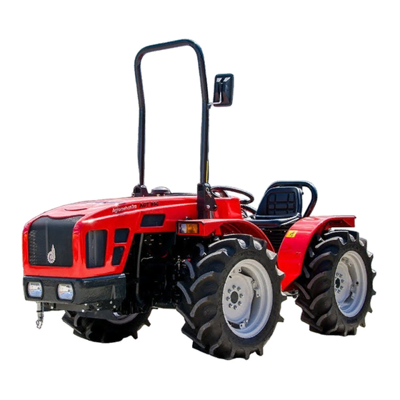
INSTRUCTIONS FOR USE 4 GENERAL DESCRIPTION OF TRACTOR AGT 850 series tractors are intended for different requirements or tasks in agriculture, gardening, forestry, and can also be used in municipal services with a few technical accessories. Thanks to its rigid transmission with different width, small turning radius, wide four-wheel drive and low centre of gravity, tractors are also suitable for work on sloping ground. -
Page 36: Description Of Tractor's Main Components
INSTRUCTIONS FOR USE 4.1 DESCRIPTION OF TRACTOR'S MAIN COMPONENTS AGT 850 / 860... - Page 37 INSTRUCTIONS FOR USE 1. Driver's seat Driver's seat is manufactured according to ergonomic principles, which means that it is adaptable to work environment of the user, according to his physical features. The seat is positioned so that the user has complete overview and simple control of control elements.
-
Page 38: Description Of Main Safety Components
INSTRUCTIONS FOR USE Reversible version of tractor – R Transmission has constant four-wheel drive and enables locking of both differentials. Front axle, wheel reducer on each side and hydraulic differential lock. Rear axle, wheel reducer on each side and hydraulic differential lock. ... - Page 39 INSTRUCTIONS FOR USE Front windshield is made of tempered glass and it opens out from below, through top hinge (1) and bottom mechanical lever (2). Front windshield is equipped with one central fitted wiper (3), controlled by individual connection in the cabin. Front windshield is wider in wide cabin version.
- Page 40 INSTRUCTIONS FOR USE E) Work lights Lights can be manually adjusted under different angles for optimal lighting of certain area. F) Rear-view mirrors Set rear-view mirrors accordingly for safe control of the tractor and implement during driving. Rear-view mirrors are set correctly, when the driver see sides of the tractor and implement without trouble.
-
Page 41: Roll Bar
INSTRUCTIONS FOR USE 4.2.2 ROLL BAR The tractor is, as standard, equipped with two roll bars, which, together, form suitably safe protection for the driver in case of any accident or tractor roll-over. IMPORTANT: Roll bars (ROPS) have been tested according to standard O.E.C.D. -
Page 42: Safety Belt
INSTRUCTIONS FOR USE Setting rear-view mirror: Setting mirror for certain angle Mirror bar enables turning around the axle. You can turn it completely in or out in case of tight area. With each desired move, you must unscrew bolt (1) on the joining point of bar and holder first. -
Page 43: Driver's Seat
INSTRUCTIONS FOR USE 4.3 DRIVER'S SEAT 4.3.1 ACCESS TO DRIVER'S SEAT To climb into the tractor and exit it, always use the step and suitable gripping points. Access to driver's seat is possible from left or right. Entry area and driver's seat must be clean, without any objects on them, which could interfere with further use. -
Page 44: Description Of Hydraulics
INSTRUCTIONS FOR USE Seat properties: Seat automatically adjusts to driver's weight (from 50 to 120 kg); Suspension system travel is 100 mm; Seat position can be set vertically up to 80 mm (height). Seat position can be set horizontally up to 150 mm (length). 4.4 DESCRIPTION OF HYDRAULICS The main element of hydraulics, through which all hydraulic elements are supplied, is the hydraulic pump, which is connected directly to the engine and connects two independent systems:... -
Page 45: Hydraulic Scheme
INSTRUCTIONS FOR USE 4.4.1 HYDRAULIC SCHEME Control block Hydraulic pump Steering head Four-way direction valve Cylinder housing Control elements Filter Connection shaft Quick coupling (implement) Choke Steering mechanism cylinder Rear part of transmission (gearbox) AGT 850 / 860... - Page 46 INSTRUCTIONS FOR USE HYDRAULIC SCHEME AGT 850 / 860...
-
Page 47: Front Hydraulic Lift System (Option)
INSTRUCTIONS FOR USE 4.4.2 FRONT HYDRAULIC LIFT SYSTEM (OPTION) The tractor can be, as option, equipped with front three-point lift mechanism, controlled by two one-way functioning hydraulic cylinders, and is fitted with connection for quick coupling for connection to hydraulic system of work implement. Front three-point lift mechanism is controlled by control elements on the right side of the tractor, near the seat. -
Page 48: Rear Hydraulic Lift Mechanism
INSTRUCTIONS FOR USE 4.4.3 REAR HYDRAULIC LIFT MECHANISM The tractor is, for towing implements, fitted, as standard, with category I three-point hitch. Three-point hitch is consisted of two lower connection arms and top connection shaft. Lower connection arms, through adjustable lift shaft, connected to lift arms, which are controlled by two one-way functioning hydraulic cylinders. - Page 49 INSTRUCTIONS FOR USE Connection to top connection shaft can be done in two versions: mechanically adjustable with ball joint (standard) in which bolt is inserted or hydraulic with ball connection or joint (option) Due to different size of tractors and work implements, three-point connection shafts are, as standard, divided into three categories.
-
Page 50: Description Of Instruments And Control Elements
INSTRUCTIONS FOR USE 4.5 DESCRIPTION OF INSTRUMENTS AND CONTROL ELEMENTS Chapter is divided in several categories for simpler description and easier understanding of all tractor control elements. Dashboard Control elements Detailed description is provided in "DESCRIPTION OF DASHBOARD CONTROL ELEMENTS". - Page 51 INSTRUCTIONS FOR USE 2. Rear connection shaft (PTO) switch If you press the switch, you engage rear connection shaft (PTO). Control light on the switch is on. Press the switch again to disengage rear connection shaft. Engaging rear connection shaft: ...
- Page 52 INSTRUCTIONS FOR USE 6. Hazard warning signal If you press the switch, you activate a warning signal and all four direction indicators start blinking. Activating hazard warning signal In position 1, hazard warning signal is deactivated (control light on the switch is off).
- Page 53 INSTRUCTIONS FOR USE Cooling liquid temperature gauge Gauge displays temperature of cooling liquid in the engine in range from 40 to 120 °C. Work temperature of tractor engine is 85 °C. Work areas: Blue zone – cold engine White zone – engine work temperature ...
- Page 54 INSTRUCTIONS FOR USE CONTROL LIGHTS 1. Warning light for electrical voltage (red) Warning light turns on before engine start or when contact key is in position 1. After engine start or engine operation, the light turns off. If the warning light for electrical voltage turns on after start or during engine operation, immediately turn off the engine, check the condition and tension of drive belt of alternator.
-
Page 55: Description Of Control Elements (Cabin)
INSTRUCTIONS FOR USE 6. Control light for direction indicators (green) If the control light is turned on, lateral left or right direction indicators, which are used to signal direction during driving, are turned on. 7. Control light for high beam lights (blue) If the control light is turned on, high beam lights, intended for using the tractor at night with lower visibility, are on. - Page 56 INSTRUCTIONS FOR USE 2. Adjustable slots for air supply Slots enable supply of fresh air into the cabin through the fan. To change air flow direction, slots turn rotationally and adapt to driver or user needs. 3. Internal cabin light Internal light illuminates driver's area in the cabin.
-
Page 57: Description Of Control Elements For Driving (Pedals)
INSTRUCTIONS FOR USE 4.5.3 DESCRIPTION OF CONTROL ELEMENTS FOR DRIVING (PEDALS) 9 3.1 1. Foot brake Two hydraulic disc brakes on rear drive shaft in oil bath, which are activated with two independent brake pedals. A – brake pedal, braking of rear left wheel B –... - Page 58 INSTRUCTIONS FOR USE 2. Handbrake Handbrake functions through lever completely independent of work brakes. It is intended mostly for blocking the wheels, when the tractor is stopped, when idling or when the tractor is completely stopped. 3. Clutch pedal Clutch pedal controls the clutch when taking off and shifting. Clutch control is performed with pedal on the left side of the driver's seat.
-
Page 59: Description Of Control Elements For Work (Connection Shaft)
INSTRUCTIONS FOR USE 4.5.4 DESCRIPTION OF CONTROL ELEMENTS FOR WORK (CONNECTION SHAFT) Reversible version of tractor (R) GEARBOX Lever has function of selecting operation mode of connection shaft. For connection shaft operation, shift the lever (1) and turn on the switch to activate hydraulic multi disc clutch. -
Page 60: Description Of Control Elements For Hydraulics
INSTRUCTIONS FOR USE 4.5.5 DESCRIPTION OF CONTROL ELEMENTS FOR HYDRAULICS Control element is a steering unit with control levers, with which we direct oil flow from tractor's pressure circuit to hydraulic outputs of internal or external hydraulic users. Tractors are, as standard, equipped with control element with three control levers. If the tractor has, as option, an added front hydraulic lift mechanism, control element with four control levers is installed. - Page 61 INSTRUCTIONS FOR USE Control lever has three positions: Position "1" – supply of oil under pressure, control lever returns to neutral position automatically Position "0" – neutral position Position "1" – supply of oil under pressure, control lever returns to neutral position automatically One-/two-way control valve This valve is very similar to two-way functioning control valve, but in can be, with a special screw, transformed into one-way functioning control valve.
- Page 62 INSTRUCTIONS FOR USE CONTROL OF HYDRAULICS THROUGH QUICK COUPLING (SINGLE) Control lever B Control lever redirects oil from pressure circuit through one-way functioning directional control valve through hydraulic output or quick coupling, for control of external hydraulic connections with one-way functioning hydraulic cylinder (e.g.
- Page 63 INSTRUCTIONS FOR USE This applies to standard tractor version, without installed front hydraulic lift mechanism. If the front hydraulic lift mechanism (option) is installed, there are, in addition to two quick couplings on the rear, two other quick couplings on the front of the tractor. In this case, oil is supplied under pressure through control lever into both pairs of quick couplings simultaneously.
-
Page 64: Optional Equipment
INSTRUCTIONS FOR USE 4.6 OPTIONAL EQUIPMENT This chapter describes optional equipment, which can be installed according to demands of the tractor user. Rear lift mechanism Hydraulic top connection shaft Floating hydraulics Front lift mechanism Front hydraulic connection (quick coupling) Weights Rotation light Control elements 4.6.1 REAR LIFT MECHANISM... - Page 65 INSTRUCTIONS FOR USE Ball connection (quick connection) Rear lift mechanism with ball connection on lower connection arms of three point type and enables quicker connections to different types of implements. Mechanism with ball connection is, as option, available in several versions: ...
-
Page 66: Front Lift Mechanism
INSTRUCTIONS FOR USE 1 Standard (mechanic) top connection shaft 2 Hydraulic top connection shaft (top link) Enables hydraulic adjustment of top connection shaft or crossbar for connection on third point of implement through shift lever, directly from the driver's seat. 4.6.2 FRONT LIFT MECHANISM Front lift mechanism is of three point type with adjustable lower connection arms. -
Page 67: Wheel Dimensions
INSTRUCTIONS FOR USE 4.6.4 WHEEL DIMENSIONS The tractor can be, as option, fitted with wheels of different dimensions. Basic dimensions are described further on, but there is also option of adjusting rims for track width. Adjustable rims (5.5x16, W8x16, W8x18, W9x18). To set track with adjustable rims, see chapter Technical data. -
Page 68: Rotation Light
INSTRUCTIONS FOR USE 4.6.7 ROTATION LIGHT As option, tractor can be fitted with a rotation light (only with an installed cabin). On tractor with cabin, fitted with front lift mechanism, rotation light is fitted as standard. 4.6.8 FLOATING HYDRAULICS WITH SUPPORT The tractor can, as additional equipment, also be fitted with floating hydraulics or system for loading the tractor on surface and unburdening the weight of the implement on surface. - Page 69 INSTRUCTIONS FOR USE HYDRAULIC SCHEME LEGEND 1. Three-directional valve 2. Pressure gauge 3. Floating hydraulics battery 4. Hydraulic pump 5. Rear part of transmission (gearbox) 6. Control elements 7. Oil filter AGT 850 / 860...
-
Page 70: Hydraulic Brake Of Towed Implement
INSTRUCTIONS FOR USE 4.6.9 HYDRAULIC BRAKE OF TOWED IMPLEMENT The tractor can be, as additional equipment, also fitted with system for connection of towed implements with hydraulic brake. Operation When pressing the brake pedal, wire rope activates lever on the brake valve mechanism for trailer. Brake valve redirects oil from pressure circuit through hydraulic conductor to brake system of towed implement and the implement begins to brake on its own. - Page 71 INSTRUCTIONS FOR USE WARNING: Brake system of the tractor does not allow separate operation of foot and hand brake. Due to pressure in the pressure circuit of the tractor with activated brakes, connecting or disconnecting can be performed only when the brake is not engaged! WARNING: Because the wire rope is connected only with one pedal, both brake pedals must be mechanically connected with a pin during driving! ADJUSTMENT OF WIRE ROPE...
- Page 72 INSTRUCTIONS FOR USE HYDRAULIC SCHEME LEGEND 1. Quick coupling 2. Trailer brake valve 3. Brake valve battery 4. Hydraulic pump 5. Rear part of transmission (gearbox) 6. Control elements 7. Oil filter AGT 850 / 860...
-
Page 73: Premium Hydraulics (Option)
INSTRUCTIONS FOR USE 4.7 PREMIUM HYDRAULICS (OPTION) Premium hydraulics is installed on the tractor as additional equipment. Due to large number of hydraulic functions, tractor enables the user with a wide spectre of use and is suitable for work in different fields. Premium hydraulics, beside standard hydraulic control, is also consisted of: Control element (four control levers);... - Page 74 INSTRUCTIONS FOR USE HYDRAULIC SCHEME 10.3 10.2 10.1 AGT 850 / 860...
- Page 75 INSTRUCTIONS FOR USE HYDRAULIC SCHEME AGT 850 / 860...
-
Page 76: Description Of Control Elements For Hydraulics
INSTRUCTIONS FOR USE 4.7.2 DESCRIPTION OF CONTROL ELEMENTS FOR HYDRAULICS Control element is a steering unit with control levers, with which we direct oil flow from tractor's pressure circuit to hydraulic outputs of internal or external hydraulic users. The tractor is equipped with two control elements with three or four control levers. Each lever performs certain function through control valve. -
Page 77: Positioning Of Control Valves
INSTRUCTIONS FOR USE DETENT Version B (NT70) Control lever has four positions: Position "1" – supply of oil under pressure, control lever returns to neutral position automatically Position "0" – neutral position Position "2" – supply of oil under pressure, control lever returns to neutral position automatically ... -
Page 78: Functioning Of Control Elements For Hydraulics
INSTRUCTIONS FOR USE lever 4 control one two-way functioning 6/4- directional control valve version B for control implements with two-way functioning hydraulic cylinder (standard for connection and control of rear hydraulic lift mechanism) 4.7.5 FUNCTIONING OF CONTROL ELEMENTS FOR HYDRAULICS Basic distribution of functions, according to control levers, is described in the following. - Page 79 INSTRUCTIONS FOR USE CONTROL ELEMENT (FOUR CONTROL LEVERS) Distribution of functions, according to control levers, is described in the following. CONTROL OF HYDRAULICS THROUGH QUICK COUPLING (DOUBLE) Control lever A Control lever redirects oil from pressure circuit through two-way functioning 6/3-directional control valve through hydraulic output or quick coupling, to control external hydraulic implements with two-way functioning hydraulic cylinder.
- Page 80 INSTRUCTIONS FOR USE Operation: If you move the lever up to position 1, one-way functioning hydraulic cylinder on the implement is supplied with oil under pressure, and the hydraulic cylinder starts to rise. When you release it, the lever on the control element automatically returns to neutral position 0. Hydraulic cylinder remains on lift position.
- Page 81 INSTRUCTIONS FOR USE CONTROL ELEMENT (THREE CONTROL LEVERS) Distribution of functions, according to control levers, is described in the following. CONTROL OF HYDRAULICS THROUGH QUICK COUPLING (DOUBLE) Control lever E Control lever redirects oil from pressure circuit through two-way functioning 6/4-directional control valve (version A) directly to quick coupling, to control implement with two-way functioning hydraulic cylinder.
-
Page 82: Connection Shaft Operation
INSTRUCTIONS FOR USE 4.7.6 CONNECTION SHAFT OPERATION Functions, which are installed on the tractor as standard, e.g. start of connection shaft, rotation of connection shaft according to operation mode, shut-off of connection shaft, start choke for soft start – PTO), are described in chapter "START OF CONNECTION SHAFT (PTO)". Additional function of premium hydraulics is soft start with activation by switch (description below). - Page 83 INSTRUCTIONS FOR USE LIFTING LOWERING INLET INLET OUTLET OUTLET INLET TANK OUTLET TANK Rear hydraulic lift mechanism is controlled with control lever: if you move it in position (1), the mechanism begins rising, and in position (2) the mechanism begins lowering. For detailed description see chapter "OPERATION OF CONTROL ELEMENTS FOR HYDRAULICS".
-
Page 84: Operation Of 3-Directional Valve
INSTRUCTIONS FOR USE Float position (FLOAT – lever in position 3) 4.7.8 OPERATION OF 3-DIRECTIONAL VALVE On rear hydraulic lift mechanism of the tractor, it is possible to transform two-way hydraulic cylinder into one-way with additional three-directional control valve, which is fitted to the right of the driver's seat. ... -
Page 85: Premium Plus Hydraulics
INSTRUCTIONS FOR USE 4.8 PREMIUM PLUS HYDRAULICS Newer version of the tractor with Premium equipment has, beside existing hydraulics, additionally integrated system of floating hydraulics with support. This keeps the operation of control elements, connection shaft and chokes of rear hydraulic cylinders the same. Besides existing Premium hydraulics, the following items are additionally installed: 1. - Page 86 INSTRUCTIONS FOR USE HYDRAULIC SCHEME 10.3 10.2 10.1 AGT 850 / 860...
-
Page 87: Operation Of Floating System
INSTRUCTIONS FOR USE 4.8.2 OPERATION OF FLOATING SYSTEM To turn it on, first, press switch (1) on the dashboard, then shift control lever for control of rear hydraulic lift mechanism into position 3 (see chapter "PREMIUM HYDRAULICS – OPERATION OF CONTROL ELEMENTS"), and the floating system with support begins operating. -
Page 88: Control Block Of Hydraulic System
INSTRUCTIONS FOR USE 4.8.3 CONTROL BLOCK OF HYDRAULIC SYSTEM Control block, beside pressure regulation in floating system, also has the function of transforming two- way hydraulic cylinder into one-way, which replaces three-directional valve in existing Premium hydraulics. To transform into two-way functioning of hydraulic cylinder, turn adjustment knob (1) on block clockwise. -
Page 89: Description Of Devices For Using The Tractor In Road Traffic
INSTRUCTIONS FOR USE 4.9 DESCRIPTION OF DEVICES FOR USING THE TRACTOR IN ROAD TRAFFIC Headlights 1. Low beam 2. High beam Side lights 3. Position lights 4. Front indicators Rear lights 5. Rear indicators 6. Reflectors 7. Low beam and brake light 8. -
Page 90: Electric Starter
INSTRUCTIONS FOR USE Access To access the battery, raise the cover. The battery is on the tank, right at the beginning. Occasionally check electrolyte level (amount must be between MIN and MAX mark), add distilled water, if required, if provided for by battery version. In the winter and at low external temperatures, when not using the tractor for a longer period of time, remove the battery from the tractor and store it in a warm area.
Need help?
Do you have a question about the AGT 860 and is the answer not in the manual?
Questions and answers